Isuzu Amigo / Axiom / Trooper / Rodeo / VehiCross. Service manual - part 1102


  Index      Isuzu     Isuzu Amigo / Axiom / Trooper / Rodeo / VehiCross - service and repair manual 1999-2002 year


Search            


Content   ..  1100  1101  1102  1103   ..


Isuzu Amigo / Axiom / Trooper / Rodeo / VehiCross. Service manual - part 1102


POWER-ASSISTED STEERING SYSTEM

2A–45

5. Remove the engine hood opening lever, then 

remove instrument panel lower cover.

6. Remove driver knee bolster (reinforcement).

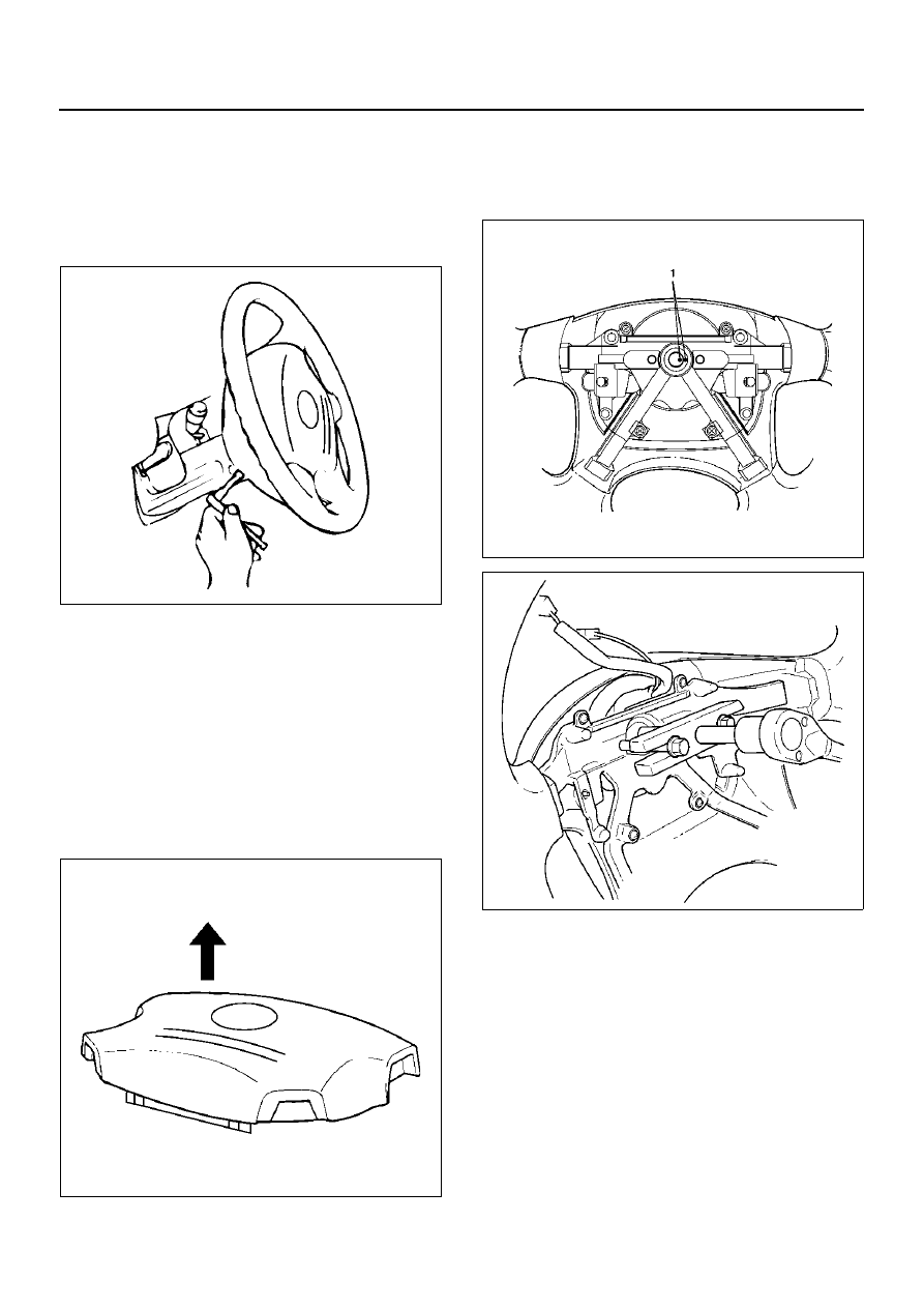
7. Loosen the inflator module fixing bolt from behind 

the steering wheel assembly using a TORX® driver 
or equivalent until the inflator module can be 
released from steering assembly.

827RW070

8. Disconnect the yellow 2-way SRS connector and 

horn lead located behind the inflator module.

9. Remove inflator module. 

WARNING:  THE INFLATOR MODULE SHOULD 
ALWAYS BE CARRIED WITH THE TRIM COVER 
AWAY FROM YOUR BODY AND SHOULD ALWAYS 
BE LAID ON A FLAT SURFACE WITH THE 
URETHANE SIDE UP. THIS IS NECESSARY 
BECAUSE FREE SPACE IS PROVIDED TO ALLOW 
THE AIR CUSHION TO EXPAND IN THE UNLIKELY 
EVENT OF ACCIDENTAL DEPLOYMENT. 
OTHERWISE, PERSONAL INJURY MAY RESULT.

827RW072

10. Apply a setting mark (1) across the steering wheel 

and shaft so parts can be reassembled in their 
original position. Move the front wheels to the 
straight ahead position, then use steering wheel 
remover J–29752 to remove the steering wheel.

430RW021

430RX005

11. Remove steering column cover.

12. Disconnect the wiring harness connectors located 

under the steering column.

2A–46

POWER-ASSISTED STEERING SYSTEM

13. Remove the combination switch assembly with SRS 

coil.

825RW288

14. Remove snap ring.

15. Remove cushion rubber.

16. Remove shift lock cable (For A/T).

17. Disconnect the starter switch harness connector 

located under the steering column, then remove 
lock cylinder assembly.

18. Apply a setting mark (1) across the universal joint 

and second steering shaft to reassemble the parts in 
their original position, then remove steering column 
assembly and second shaft.

NOTE:  A setting mark can be easily made if the shaft is 
withdrawn a little by loosening the steering shaft 
universal joint.

431RW009

Insepction

If the abnormal conditions are found through inspection, 
replace the steering column assembly.

Column Capsule

Check capsules on steering column bracket assembly; 
all must be securely seated in bracket slots and 
checked for any loose conditions when pushed or pulled 
by hand.

431RW030

Check clearance between capsule and bracket. If must 
be within 1mm (0.039 in).

431RW031

POWER-ASSISTED STEERING SYSTEM

2A–47

Column Tube

Check for collapes by measuring the distance as shown 
in the figure.

Standard distance: 162.2-165.8 mm (6.386-6.528 
in)

431RY00005

E nd O FCallo ut

Column Universal Joint for Tilt Mechanism

Check steering column assembly for any resistance by 
rotating the universal joint. If resistance is felt   then 
replace the steering column assembly.

Sheared Injected Plastic Pin

Check the sheared injected plastic pins for any loose 
conditions or damage.

431RY00006

E nd OFC allou t

Shaft Length

Check the shaft length from the upper end of the slide 
joint to the end of the shaft. If column length is not in 
specifications, steering column should be replaced.

Standard length:

NON TILT TYPE: 540.9 –542.9 mm (21.295–

21.374 in)

TILT TYPE: 291.7 –295.7 mm (11.484 – 11.642 in)

431R200007

E nd OFC allou t

Legend

(1)

NON TILT TYPE

(2)

TILT TYPE

Legend

(1)

NON TILT TYPE

(2)

TILT TYPE

Legend

(1)

NON TILT TYPE

(2)

TILT TYPE

2A–48

POWER-ASSISTED STEERING SYSTEM

Shaft Universal Joint (Lower End)

If the resistance is felt when checked by rotate the joint, 
replace the steering column assembly.

Shaft Bellows Pipe

Use a straightedge to inspect the shaft bellows pipe for 
straightness. Replace if the clearance is   more than the 
specifications.

Standard: Less than 1mm (0.039 in)

431RW035

Tilt Mechanism

Tilt mechanism should moves smoothly.
While locked the tilt mechanism, be sure the steering 
column latch securely by pushing the steering wheel 
upward and downward.

Installation

1. Install steering column assembly and second 

steering shaft.

2. Align the setting marks on the universal joint and 

second steering shaft made during removal.

3. Tighten the steering column fixing bolt (dash panel) 

to the specified torque.

Torque: 20 N·m  (14 lb ft)

4. Tighten the steering column fixing nuts (cross 

beam) to the specified torque.

Torque: 17 N·m  (12 lb ft)

5. Tighten the universal joint to the specified torque.

Torque: 31 N·m  (23 lb ft)

6. Install lock cylinder assembly.

7. Install shift lock cable (For A/T).

8. Install cushion rubber.

9. Install snap ring.

10. Install combination switch and SRS coil assembly. 

After installation of combination switch assembly,  
connect the combination switch wiring harness 
connector and the SRS 2-way connector located 
under the steering column.

11. Turn the SRS coil counter clockwise to full, return 

about 3 turns and align the neutral mark.

CAUTION:  Turn the SRS coil counter clockwise 
until a resistance is felt or damage to the SRS coil   
may occur from over turning.

825RW016

12. When installing the steering column cover, be sure 

to route each wire harness as illustrated so that the 
harnesses do not catch any moving parts.

825RW017

E nd OFCa llou t

Legend

(1)

Steering Column Cover

(2)

Starter Switch Harness

(3)

Combination Switch Harness

(4)

Inflator Module Harness


Content   ..  1100  1101  1102  1103   ..