Isuzu Trooper (1998-2002 year). Service manual - part 382
6A–58
ENGINE MECHANICAL (6VE1 3.5L)
3. Install valve to valve guide. Before installing valve
guide apply engine oil to the outside of the valve stem.
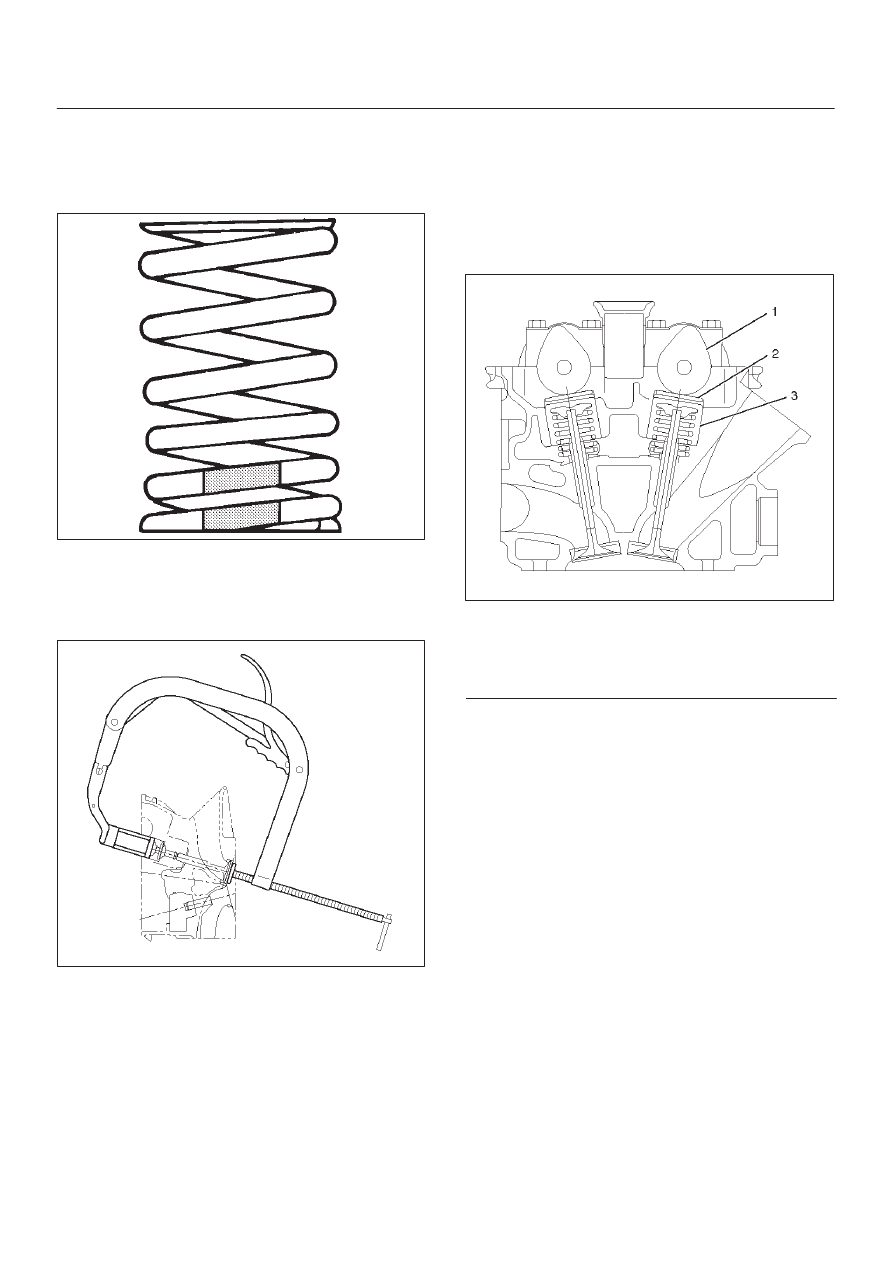
4. Install valve spring to cylinder head. Attach the valve
spring to the lower spring seat. The painted area of
the valve spring should be facing downward.
014RS020
5. Install lower valve spring seat, valve spring and upper
valve spring seat then put split collars on the upper
spring seat, using the 5-8840-2446-0 valve spring
compressor and 5-8840-2547-0 valve spring
compressor adapter to install the split collars.
014RW042
6. Install tappet with shim.
7. Install camshaft assembly.
D
Refer to installation procedure for Camshaft in this
manual.
Valve Clearance Adjustments
NOTE: To adjust valve clearance, apply engine oil to the
cam as well as to the adjusting shim (2) with the cylinder
head built on the cylinder block, give a few turns to the
camshaft by means of timing pulley tightening bolt, and
measure valve clearance when the nose of cam is just
opposite of maximum cam lift (1) as shown in illustration
below.
014RW081
Legend
(1) Cam
(2) Shim
(3) Tappet
Valve Clearance Standard Value (cold)
Intake: 0.23 mm–0.33 mm
(0.0091 in–0.0130 in)
Exhaust: 0.25 mm–0.35 mm
(0.0098 in–0.0138 in)
Selection of Adjusting Shim
Shim to be selected = (Thickness of removed shim) +
(Valve clearance measurement – Standard value)
Based on the above formula, the best suited shim should
be selected from 41 types of shim (differently thick at
0.02mm (0.0008 in) intervals from 2.40mm (0.0945 in)
through 3.2mm (0.1260 in) thick). Install the shim and
check valve clearance.