Isuzu engine 4j series. Service manual - part 94
 

  Index      Isuzu     Isuzu engine 4j series - manual


Search            


Content   ..  92  93  94  95   ..


Isuzu engine 4j series. Service manual - part 94


QOSIII PREHEATING SYSTEM  6D7 – 7

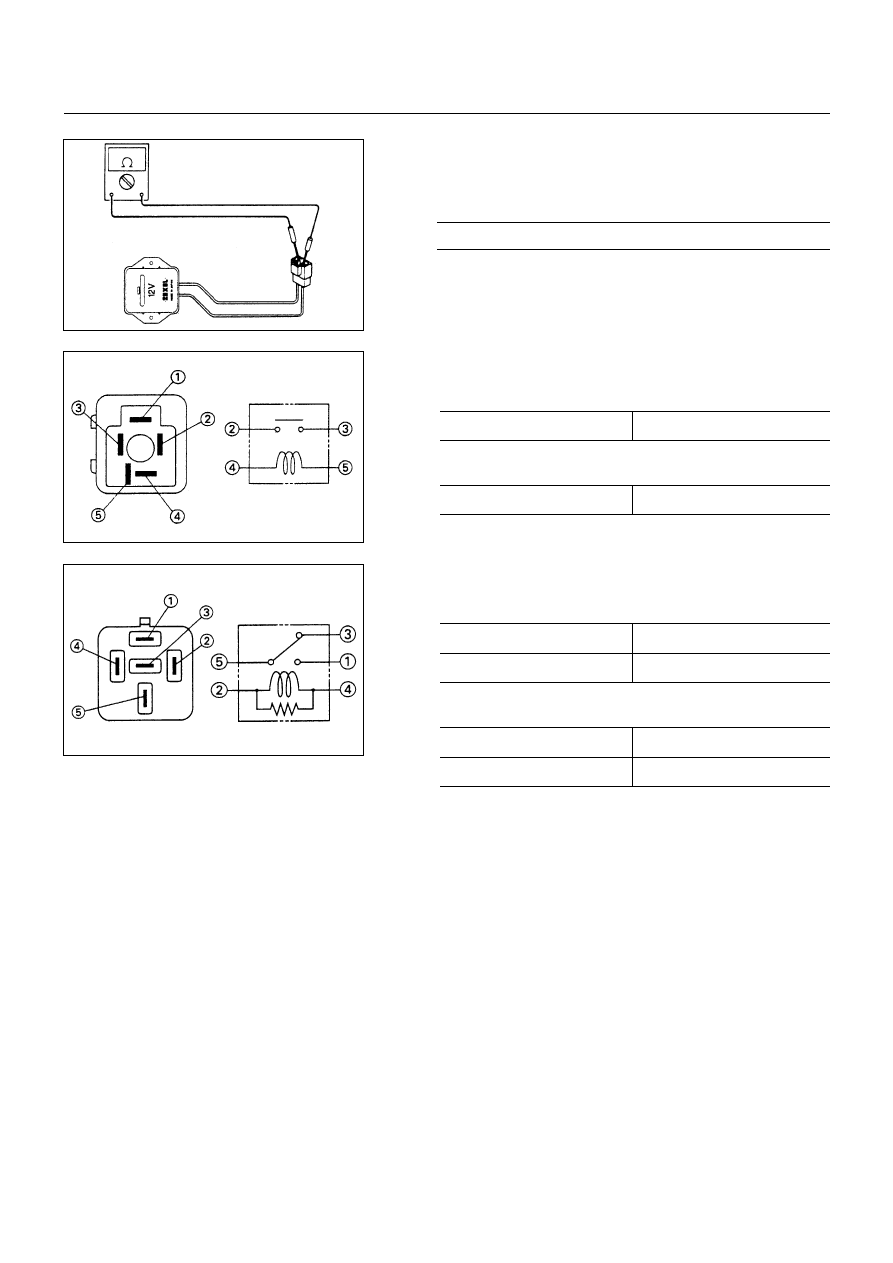
DROPPING RESISTOR

Inspect the resistance

Resistance of normal ambient temperature

m


225 ~ 255


GLOW PLUG RELAY

Inspect the continuity

!

 - 

"

No Continuity

If apply the battery voltage to terminal between 

#

 - 

$

!

 - 

"

Continuity

CHARGE RELAY

Inspect the continuity

"

 - 

$

Continuity

%

 - 

$

No Continuity

If apply the battery voltage to terminal between 

!

 - 

#

"

 - 

$

No Continuity

%

 - 

$

Continuity

6D7-7-1.tif

6D7-7-2.tif

6D7-7-3.tif

EXHAUST GAS RECIRCULATION (EGR) SYSTEM  6E– 1

SECTION 6E

EXHAUST GAS RECIRCULATION (EGR) SYSTEM

CONTENTS

PAGE

General Description........................................................................................................... 6E -2

EGR System Wiring Diagram............................................................................................ 6E -3

EGR System Operation ..................................................................................................... 6E -3

EGR System Check ........................................................................................................... 6E -4

Inspection........................................................................................................................... 6E -5

HOME

6E – 2  EXHAUST GAS RECIRCULATION (EGR) SYSTEM

GENERAL DESCRIPTION

This system controls the formation of NOx emission by recirculating the exhaust gas into the combustion chamber
through the intake manifold.

The EGR valve are controlled by VSV, also VSV are controlled by EGR controller according to signals from RPM
sensor and Potentiometer.

The amount of EGR depends on the number of engine rotations and the opening of the accelerator.

D06LX001.tif

EXHAUST GAS RECIRCULATION (EGR) SYSTEM  6E– 3

EGR SYSTEM WIRING DIAGRAM

1. CONNECTOR PIN ASSIGNMENT

No.

CONNECTOR NAME

1

-

2

Battery (-) c/u GND

3

Thermo Switch

4

Battery (+)

5

-

6

-

7

rpm Signal (+)

8

rpm Signal (-)

9

Potentio Meter (+)

10

Potentio Meter

11

Potentio Meter (-)

12

-

13

VSV

EGR SYSTEM OPERATION

1) On the input side of engine speed, there is provided a

hysteresis of 50 rpm on the speed rising side.

2) It does not work until 70 sec, pass after engine start.

3) It does not work while the water temperature switch is

on (30°C or lower).

4) While engine speed drops from 3,800 rpm or higher, it

does not work for 25 sec.

13-01.tif

056LX016.tif

826LX007.tif

(above 40

℃: OFF)

(below 30

℃: ON)


Content   ..  92  93  94  95   ..