Isuzu Trooper (2000 year). Service manual - part 84
4A2–18 DIFFERENTIAL (REAR)
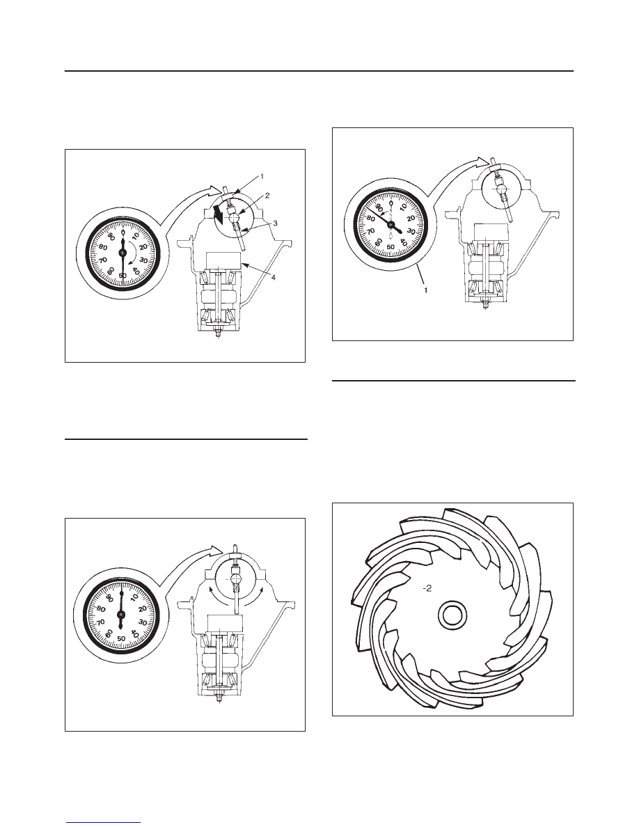
4. Set the dial indicator J–8001 to “0”. Place it on the
mounting post of the gauging arbor with the
contact button touching the indicator pad. Force
the dial indicator downward until the needle has
made a half turn clockwise. Tighten down the dial
indicator in this position.
425RS020
Legend
(1) Dial Indicator
(2) Ganging Arbor
(3) Plunger
(4) Gauge Plate
5. Position the plunger on the gauge plate. Move the
gauging arbor slowly back and forth and locate
the position at which the dial indicator shows the
greatest defection. At this point, once again set
the dial indicator to “0”. Repeat the procedure to
verify the “0” setting.
425RS021
6. After the ZERO setting is obtained, rotate the
gauging arbor until the dial indicator rod does not
touch the gauging plate. Record the number the
dial indicator needle points to.
425RS022
Legend
(1) Example=Dial indicator reading od 0.085
7. Record the pinion depth code on the head of the
drive pinion. The number indicates a necessary
change in the pinion mounting distance. A plus
number indicates the need for a greater mounting
distance (which can be achieved by decreasing
the shim thickness). A minus number indicates
the need for a smaller mounting distance (which
can be achieved by increasing the shim
thickness). If examination reveals pinion depth
code “0”, the pinion is “nominal”.
425RS023