Isuzu Trooper (2000 year). Service manual - part 52
2A–38
POWER ASSISTED SYSTEM
Installation
1. Install inner rod end and align the setting marks
applied during disassembly.
2. Tighten the inner lock nut to specified torque.
Torque: 118 N·m (87 lb ft)
NOTE: For either outer rod, the screw on the right side of
the vehicle is threaded counterclockwise.
3. Install outer rod end assembly and align the setting
marks applied during disassembly.
4. Tighten the outer lock nut to specified torque.
Torque: 118 N·m (87 lb ft)
5. Install knuckle arm nut and cotter pin then tighten the
nut to the specified torque, with just enough additional
torque to align cotter pin holes. Install new cotter pin.
Torque: 98 N·m (72 lb ft)
6. Install center track rod and nut and cotter pin then
tighten the nut to the specified torque, with just
enough additional torque to align cotter pin holes.
Install new cotter pin.
Torque: 98 N·m (72 lb ft)
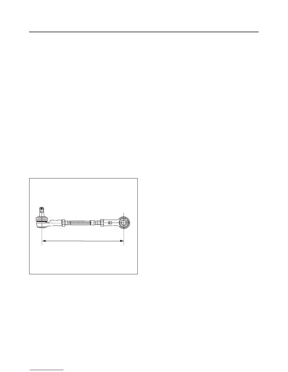
NOTE: If replacing the track rod, adjust the new track rod
length.
Rod length: 328.3 mm (12.93 in)
433RS016
NOTE: Adjust the toe-in. Refer to Front End Alignment
Inspection and Adjustment in this section.