Isuzu Rodeo UE. Service manual - part 436
6E2–499
RODEO 6VD1 3.2L ENGINE DRIVEABILITY AND EMISSIONS
A fuel injector which is stuck partly open will cause a loss
of fuel pressure after engine shut down, causing long
crank times.
0003
Fuel Metering System Components
The fuel metering system is made up of the following
parts:
f
The fuel injectors.
f
The throttle body.
f
The fuel rail.
f
The fuel pressure regulator.
f
The PCM.
f
The crankshaft position (CKP) sensor.
f
The camshaft position (CMP) sensor.
f
The idle air control (IAC) valve.
f
The fuel pump.
f
The fuel pump relay.
Basic System Operation
The fuel metering system starts with the fuel in the fuel
tank. An electric fuel pump, located in the fuel tank,
pumps fuel to the fuel rail through an in-line fuel filter. The
pump is designed to provide fuel at a pressure above the
pressure needed by the injectors. A fuel pressure
regulator in the fuel rail keeps fuel available to the fuel
injectors at a constant pressure. A return line delivers
unused fuel back to the fuel tank. Refer to
Section 6C for
further information on the fuel tank, line filter, and fuel
pipes.
Fuel Metering System Purpose
The basic function of the air/fuel metering system is to
control the air/fuel delivery to the engine. Fuel is delivered
to the engine by individual fuel injectors mounted in the
intake manifold near each intake valve.
The main control sensor is the heated oxygen sensor
(HO2S) located in the exhaust system. The HO2S tells
the PCM how much oxygen is in the exhaust gas. The
PCM changes the air/fuel ratio to the engine by controlling
the amount of time that fuel injector is “ON.” The best
mixture to minimize exhaust emissions is 14.7 parts of air
to 1 part of gasoline by weight, which allows the catalytic
converter to operate most efficiently. Because of the
constant measuring and adjusting of the air/fuel ratio, the
fuel injection system is called a “closed loop” system.
The PCM monitors signals from several sensors in order
to determine the fuel needs of the engine. Fuel is
delivered under one of several conditions called “modes.”
All modes are controlled by the PCM.
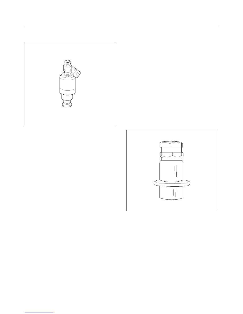
Fuel Pressure Regulator
The fuel pressure regulator is a diaphragm-operated
relief valve mounted on the fuel rail with fuel pump
pressure on one side and manifold pressure on the other
side. The fuel pressure regulator maintains the fuel
pressure available to the injector at three times
barometric pressure adjusted for engine load. It may be
serviced separate.
If the pressure is too low, poor performance and a DTC
P0131, DTC P0151,DTC P0171 or DTC P1171 will be the
result. If the pressure is too high, excessive odor and/or a
DTC P0132, DTC P0152,DTC P0172 or DTC P0175 will
be the result. Refer to
Fuel System Diagnosis for
information on diagnosing fuel pressure conditions.
0011
Fuel Pump Electrical Circuit
When the key is first turned “ON,” the PCM energizes the
fuel pump relay for two seconds to build up the fuel
pressure quickly. If the engine is not started within two
seconds, the PCM shuts the fuel pump off and waits until
the engine is cranked. When the engine is cranked and
the 58 X crankshaft position signal has been detected by
the PCM, the PCM supplies 12 volts to the fuel pump relay
to energize the electric in-tank fuel pump.
An inoperative fuel pump will cause a “no-start” condition.
A fuel pump which does not provide enough pressure will
result in poor performance.
Fuel Rail
The fuel rail is mounted to the top of the engine and
distributes fuel to the individual injectors. Fuel is
delivered to the fuel inlet tube of the fuel rail by the fuel
lines. The fuel goes through the fuel rail to the fuel