Isuzu KB P190. Service manual - part 938
 

  Index      Isuzu     Isuzu KB P190 - service and repair manual 2007 year


Search            


Content   ..  936  937  938  939   ..


Isuzu KB P190. Service manual - part 938


Exhaust System – V6 

Page 6F –  4 


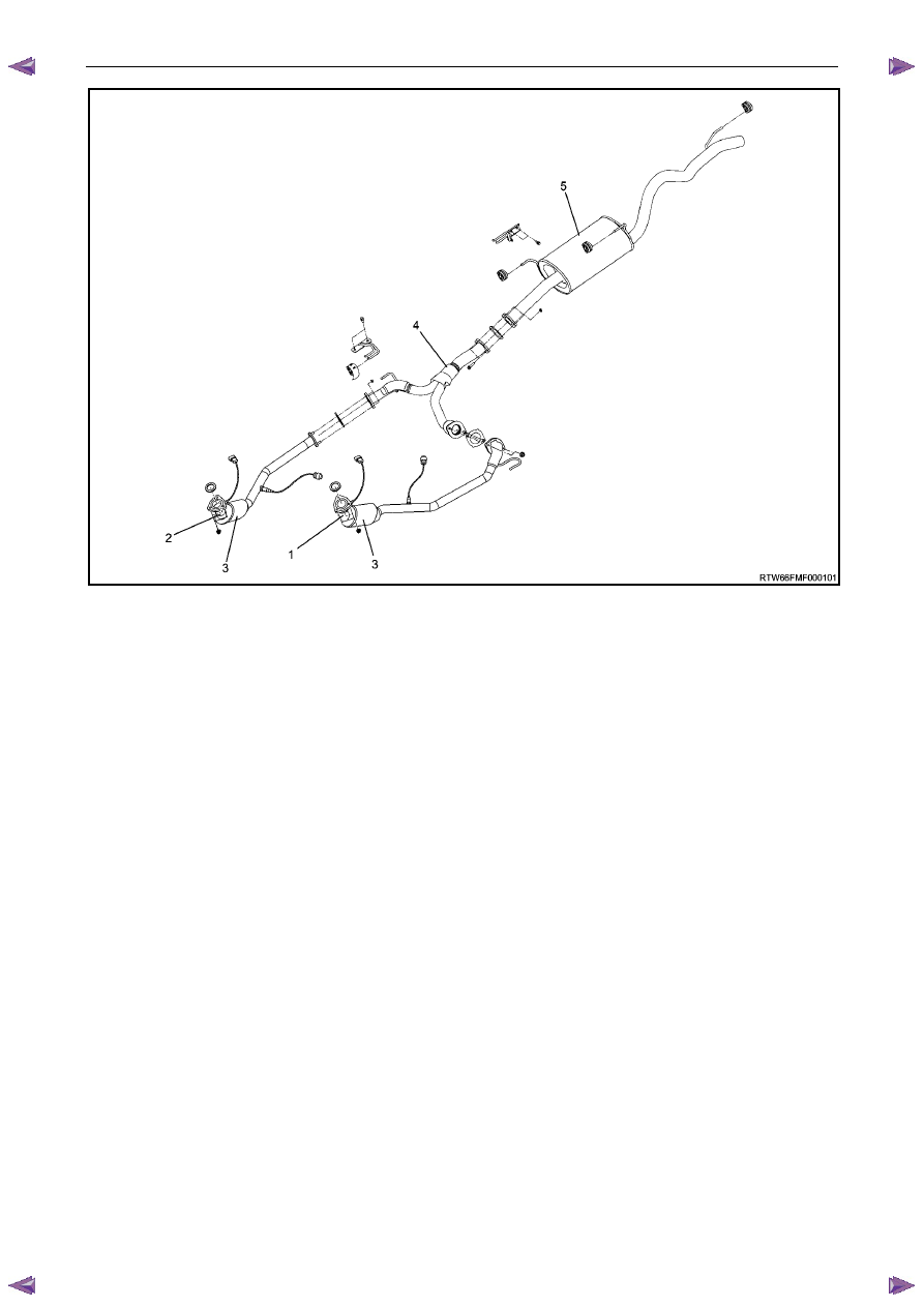
Figure 6F– 3 

Legend 

Front Exhaust Pipe LH side 

Front Exhaust Pipe RH side 

Three Way Catalytic Converter 

Centre Exhaust Pipe 

Exhaust Silencer and Tail Pipe 

1.2 General 

Description 


When inspecting or replacing the exhaust system components, make sure there is adequate clearance from all points 
on the underbody to prevent overheating of the floor pan and possible damage to the passenger compartment insulation 
and trim materials. Check complete exhaust system and nearby body areas and rear compartment lid for broken , 
damaged, missing or misaligned components, open seams, holes, loose connections or other deterioration which could 
permit exhaust fumes to seep into the rear compartment or passenger compartment. Dust or water in the rear 
compartment may be an indication of a problem in one of  these areas. Any faulty areas should be corrected 
immediately. 

Various types of hangers are used to support exhaust systems, these include conventional rubber straps, rubber rings 
or rubber blocks. The installation of exhaust system supports is very important, Improperly installed supports can cause 
annoying vibrations which can be difficult to diagnose. 


Exhaust System – V6 

Page 6F –  5 


Service Notes 

1.  Vehicles fitted with catalytic converters should not be operated with leaded petrol. Lead will contaminate 

the ceramic monolith. 

2.  Do not drop the catalytic converter as it will damage the ceramic monolith. 

3.  Replace the catalytic converter if it is damaged. 

4.  Do not allow water, oil or fuel to enter the converter as the ceramic monolith will be contaminated. 

5.  Do not use engine and/or fuel additives unless approved by General Motors. Many additives contain 

phosphorous that will contaminate the ceramic monolith. 

6.  The vehicle must not be started by pushing or towing, as unburned fuel could reach the catalytic 

converter and destroy the ceramic monolith. Always use jumper leads to start a vehicle that has a flat or 
defective battery. 

7.  When carrying out a compression test, for V6 engines use Tech 2 to ensure the output control Engine 

Compression Test is set to enable, refer to 6A1 Engine Mechanical. This prevents fuel injection and 
ignition during engine cranking. 

8.  Do not drive the vehicle with the engine misfiring or with any of the spark plug leads disconnected, as the 

catalytic converter will overheat. 

9.  Do not coast downhill with the engine misfiring or with any of the spark plug leads disconnected. 

10.  The catalytic converter is serviceable as part of the front exhaust assembly only. Refer to the service 

operations in this section for details of front exhaust pipe assembly removal and reinstallation. 

11.  The exhaust flange gaskets must be replaced whenever a new exhaust pipe, muffler or catalytic converter 

is installed. 

1.3 

WARNING, CAUTION and NOTES 

This Section contains various WARNINGS, CAUTIONS and NOTE statements that you must observe carefully to reduce 
the risk of death or injury during service, repair procedures or vehicle operation. Incorrect service or repair procedures 
may damage the vehicle or cause operational faults. WARNINGS, CAUTION and NOTE statements are not exhaustive. 
HOLDEN LTD can not possibly warn of all the potentially hazardous consequences of failure to follow these instructions. 

1.1 Definition of WARNING, CAUTION and NOTE Statements 


Diagnosis and repair procedures in this Section contain both general and specific WARNING, CAUTION and NOTE 
statements. HOLDEN LTD is dedicated to the presentation of service information that helps the technician to diagnose 
and repair the systems necessary for proper operation of the vehicle. Certain procedures may present a hazard to the 
technician if they are not followed in the recommended manner. WARNING, CAUTION and NOTE statements are 
designed to help prevent these hazards from occurring, but not all hazards can be foreseen. 

WARNING defined 

A WARNING statement immediately precedes an operating procedure or maintenance practice which, if not correctly 
followed, could result in death or injury. A WARNING statement alerts you to take necessary action or not to take a 
prohibited action. If a WARNING statement is ignored, the following consequences may occur: 

• 

Death or injury to the technician or other personnel working on the vehicle, 

• 

Death or injury to other people in or near the workplace area, and / or 

• 

Death or injury to the driver / or passenger(s) of the vehicle or other people, if the vehicle has been improperly 
repaired. 

CAUTION defined 

A CAUTION statement immediately precedes an operating procedure or maintenance practice which, if not correctly 
followed, could result in damage to or destruction of equipment, or corruption of data. If a CAUTION statement is 
ignored, the following consequences may occur: 

• 

Damage to the vehicle, 

• 

Unnecessary vehicle repairs or component replacement, 

Exhaust System – V6 

Page 6F –  6 


• 

Faulty operation or performance of any system or component being repaired, 

• 

Damage to any system or components which depend on the proper operation of the system or component being 
repaired, 

• 

Faulty operation or performance of any systems or components which depend on the proper operation or 
performance of the system or component under repair, 

• 

Damage to fasteners, basic tools or special tools and / or 

• 

Leakage of coolant, lubricant or other vital fluids. 

NOTE defined 

A NOTE statement immediately precedes or follows an operating procedure, maintenance practice or condition that 
requires highlighting. A NOTE statement also emphasises necessary characteristics of a diagnostic or repair procedure. 
A NOTE statement is designed to: 

• 

Clarify a procedure, 

• 

Present additional information for accomplishing a procedure, 

• 

Give insight into the reasons for performing a procedure in the recommended manner, and / or 

• 

Present information that gives the technician the benefit of past experience in accomplishing a procedure with 
greater ease. 


Exhaust System – V6 

Page 6F –  7 


Front and Centre Exhaust Pipe 


Figure 6F– 4 

Front Exhaust Flange Nuts 

Front O2 Sensor 

Three Way Catalytic Converter RH side 

Rear O2 Sensor 

Three Way Catalytic Converter LH side 

Front Exhaust Pipe Mounting Rubber 

Centre Exhaust Flange Attaching Nuts 

Centre Exhaust Pipe 

Rear Exhaust Flange Nuts 


Removal 

1.  Disconnect the battery ground cable. 

2.  Remove the suspension cross member, Refer to 7B1 Manual transmission. 

3.  Remove the two front torsion bar springs, Refer to 3C Suspension. 

4.  Disconnect  the O2 sensor harness connectors (2 and 4), two each bank. 

5.  Remove the front exhaust flange attaching nuts (1), three each bank. 

6.  Remove the centre exhaust pipe flange nuts (7), two each bank. 

7.  Remove the centre exhaust pipes from the rubber mounts (6). 

8.  Remove the front left and right hand exhaust pipes from the vehicle. 

9.  Remove the two rear exhaust flange nuts and bolts (9). 

10.  Remove the centre exhaust pipe from the vehicle. 

11.  Remove the O2 sensors if required, Refer to 6C1 – 1 Engine Management General Info. 


Content   ..  936  937  938  939   ..