Isuzu KB P190. Service manual - part 902
 

  Index      Isuzu     Isuzu KB P190 - service and repair manual 2007 year


Search            


Content   ..  900  901  902  903   ..


Isuzu KB P190. Service manual - part 902


Charging System – V6 

Page 6D1-1-21 


8 Special 

Tools 

TOOL NUMBER 

ILLUSTRATION 

DESCRIPTION TOOL 

CLASSIFICATION 

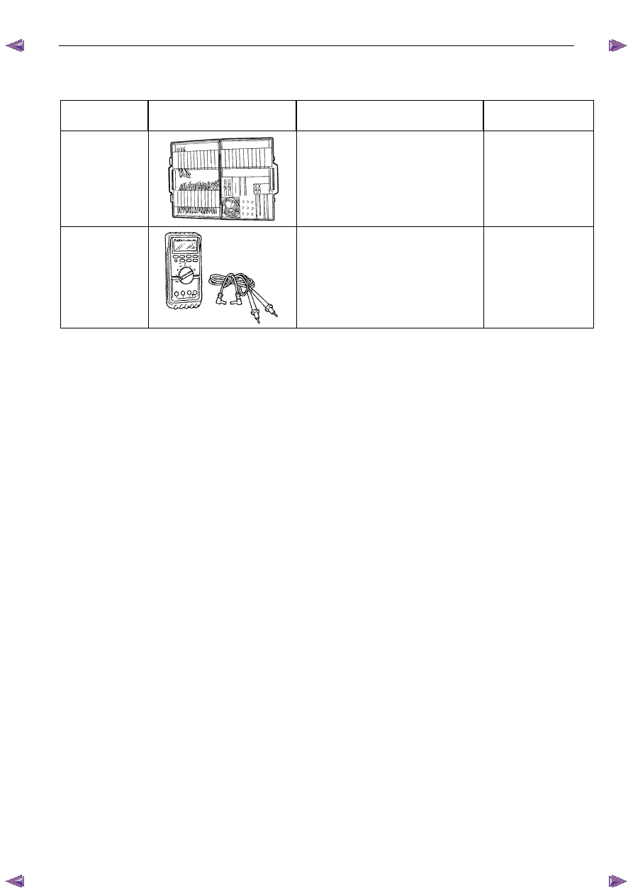
J35616-A 

(KM609) 


CONNECTOR TEST ADAPTOR KIT 

Used when carrying out electrical 
diagnostic circuit checks. 

Previously released. 

Desirable 

3588 

(J39200) 


DIGITAL MULTIMETER 

Must have at least 10 M

Ω input 

impedance and be capable of reading 
frequencies. 

Previously released. 

Available 


Starting System – V6 

Page 6D1-2–1 


6D1-2 

Starting System – V6 

A T T E N T I O N  

Before performing any service operation or other procedure described in this Section, refer to 1.1   
WARNING, CAUTION and NOTES for correct workshop practices with regard to safety and/or property 
damage. 

1


General Information ...............................................................................................................................3


1.1


 WARNING, CAUTION and NOTES ....................................................................................................................... 3


Definition of WARNING, CAUTION and NOTE Statements................................................................................. 3


WARNING defined ............................................................................................................................................. 3


CAUTION defined .............................................................................................................................................. 3


NOTE defined..................................................................................................................................................... 3


1.2


 Components .......................................................................................................................................................... 4


Starting System Components............................................................................................................................... 4


Starter Motor and Solenoid Switch Components................................................................................................ 4


Solenoid Switch.................................................................................................................................................. 4


Planetary Drive Train.......................................................................................................................................... 4


Armature ............................................................................................................................................................ 4


Brushes .............................................................................................................................................................. 4


1.3


System Operation .................................................................................................................................................. 5


Operation ........................................................................................................................................................... 5


Sequence of Operation ...................................................................................................................................... 6


2


Diagnostics .............................................................................................................................................7


2.1


Diagnostic General Information............................................................................................................................ 7


Basic Diagnostic Tools Required ......................................................................................................................... 7


2.2


Tech 2 Data List ..................................................................................................................................................... 7


2.3


Diagnostic Systems Check ................................................................................................................................... 7


2.4


Wiring Diagram ...................................................................................................................................................... 8


2.5


Starting System Inoperative / Malfunctioning ................................................................................................... 10


Circuit Description ............................................................................................................................................ 10


Diagnostic Table Notes .................................................................................................................................... 10


Diagnostic Table............................................................................................................................................... 10


Diagnostic Table – Slow Cranking, Solenoid Clicks or Chatters....................................................................... 14


3


Minor Service Operations ....................................................................................................................15


3.1


Safety Precautions............................................................................................................................................... 15


3.2


Maintenance ......................................................................................................................................................... 15


Regular Checks.................................................................................................................................................... 15


3.3


On-Vehicle Testing .............................................................................................................................................. 15


Engine Compartment Relay And Fuse Panel................................................................................................... 16


Bad Connection Test........................................................................................................................................ 16


Starter Motor Ground Test ............................................................................................................................... 17


Switching Circuit Test....................................................................................................................................... 17


Cranking Voltage Test...................................................................................................................................... 18


Current Draw Test ............................................................................................................................................ 18


4


Major Service Operations ....................................................................................................................19


4.1


Starter Motor ........................................................................................................................................................ 19


Remove ................................................................................................................................................................. 19


Starting System – V6 

Page 6D1-2–2 


Reinstall ................................................................................................................................................................ 21


4.3


Starter Motor Bench Tests .................................................................................................................................. 22


Preliminary Checks.............................................................................................................................................. 22


Pull-in Test............................................................................................................................................................ 22


Hold-in Test .......................................................................................................................................................... 23


Drive Assembly Return Test ............................................................................................................................... 23


No Load Test ........................................................................................................................................................ 24


4.4


Starter Motor Disassemble and Reassemble .................................................................................................... 25


Disassemble ......................................................................................................................................................... 25


Reassemble .......................................................................................................................................................... 26


4.5


Solenoid Switch Tests ......................................................................................................................................... 26


Test the Solenoid Switch.................................................................................................................................. 26


5


Specifications .......................................................................................................................................30


6


Torque Wrench Specifications............................................................................................................31


7


Special Tools ........................................................................................................................................32


Starting System – V6 

Page 6D1-2–3 


1 General 

Information 

All HFV6 engines are fitted with a Mitsubishi starter motor. This consists of a solenoid switch on a DC motor. The motor 
has permanent magnet excitation, which has the advantage of low weight a with high output torque and is visually 
identifiable by the absence of pole-shoe retaining screws. 

The starter motor does not have field coil windings or pole shoes. These parts have been replaced by six permanent 
magnets that are held in the pole housing by clips. The positive brushes are now part of the brush plate assembly. 

The solenoid switch is the only component of the starter motor assembly that is serviced separately. If any other parts 
require replacement, the starter motor must be replaced. 

1.1 

 WARNING, CAUTION and NOTES 

This Section contains various WARNINGS, CAUTIONS and NOTE statements that you must observe carefully to reduce 
the risk of death or injury during service, repair procedures or vehicle operation. Incorrect service or repair procedures 
may damage the vehicle or cause operational faults. WARNINGS, CAUTION and NOTE statements are not exhaustive. 
HOLDEN LTD can not possibly warn of all the potentially hazardous consequences of failure to follow these instructions. 

Definition of WARNING, CAUTION and NOTE Statements 


Diagnosis and repair procedures in this Section contain both general and specific WARNING, CAUTION and NOTE 
statements. HOLDEN LTD is dedicated to the presentation of service information that helps the technician to diagnose 
and repair the systems necessary for proper operation of the vehicle. Certain procedures may present a hazard to the 
technician if they are not followed in the recommended manner. WARNING, CAUTION and NOTE statements are 
designed to help prevent these hazards from occurring, but not all hazards can be foreseen. 

WARNING defined 

A WARNING statement immediately precedes an operating procedure or maintenance practice which, if not correctly 
followed, could result in death or injury. A WARNING statement alerts you to take necessary action or not to take a 
prohibited action. If a WARNING statement is ignored, the following consequences may occur: 

• 

Death or injury to the technician or other personnel working on the vehicle, 

• 

Death or injury to other people in or near the workplace area, and / or 

• 

Death or injury to the driver / or passenger(s) of the vehicle or other people, if the vehicle has been improperly 
repaired. 

CAUTION defined 

A CAUTION statement immediately precedes an operating procedure or maintenance practice which, if not correctly 
followed, could result in damage to or destruction of equipment, or corruption of data. If a CAUTION statement is ignored, 
the following consequences may occur: 

• 

Damage to the vehicle, 

• 

Unnecessary vehicle repairs or component replacement, 

• 

Faulty operation or performance of any system or component being repaired, 

• 

Damage to any system or components which depend on the proper operation of the system or component being 
repaired, 

• 

Faulty operation or performance of any systems or components which depend on the proper operation or 
performance of the system or component under repair, 

• 

Damage to fasteners, basic tools or special tools and / or 

• 

Leakage of coolant, lubricant or other vital fluids. 

NOTE defined 

A NOTE statement immediately precedes or follows an operating procedure, maintenance practice or condition that 
requires highlighting. A NOTE statement also emphasises necessary characteristics of a diagnostic or repair procedure. 
A NOTE statement is designed to: 


Content   ..  900  901  902  903   ..