Isuzu KB P190. Service manual - part 829
 

  Index      Isuzu     Isuzu KB P190 - service and repair manual 2007 year


Search            


Content   ..  827  828  829  830   ..


Isuzu KB P190. Service manual - part 829


Engine Management – V6 – Diagnostics 

Page 6C1-2–38 


Step Action  Value(s) 

Yes 

No 

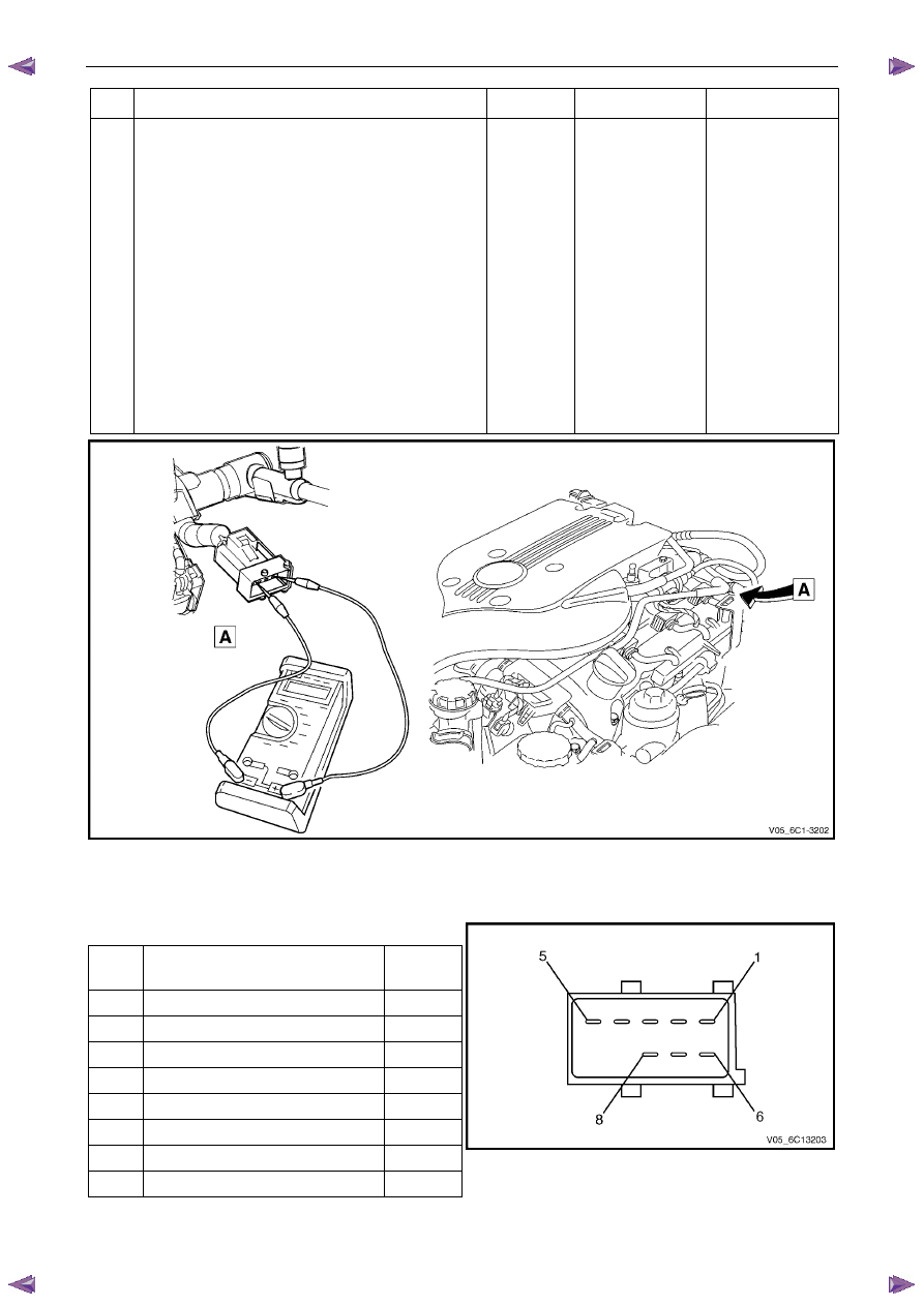
Disconnect the fuel injector harness connector, 
refer to 2.13 Fuel Rail Assembly, in 6C1-3 Engine 
Management – V6 – Service Operations. 

Using a digital ohmmeter and connector test 
adaptor kit J 35616-A, measure the resistance of 
each fuel injector between the ignition voltage 
circuit and the fuel injector control circuit. Refer to 
8A Electrical - Body and Chassis for information 
on testing for continuity and to Figure 6C1-2 – 9 
and Figure 6C1-2 – 10 for the fuel injector 
harness connector. 

Record each fuel injector value. 

Subtract the lowest resistance value from the 
highest. 

Is the difference equal to, or less than, the specified 
value? 

Ω 

Injectors OK 

Refer to Injector 
Coil Test – With 

Special Tool J39021

in this Section. 


Figure 6C1-2 – 9 

Fuel Injector Harness to Engine Harness Connector 

Pin Description 

Pin Function 

Circuit 

Number

Ignition Voltage Circuit – Cyl. 1, 3, 5 

639 

Ignition Voltage Circuit – Cyl. 2, 4, 6 

1039 

Injector 1 Control Circuit 

1744 

Injector 3 Control Circuit 

1746 

Injector 5 Control Circuit 

845 

Injector 2 Control Circuit 

1745 

Injector 4 Control Circuit 

844 

Injector 6 Control Circuit 

846 


Figure 6C1-2 – 10 

Engine Management – V6 – Diagnostics 

Page 6C1-2–39 


Injector Coil Test – With Special Tool J39021 

Depressurise the fuel system, refer to 6C Fuel System – V6. 

Turn the ignition OFF. 

N O T E  

After removing the upper intake manifold, plug 
the lower manifold opening to prevent dirt and 
other contaminants from entering. 

Remove the upper intake manifold assembly, refer to 6A1 Engine Mechanical – V6. 

Using Tech 2, observe the engine coolant temperature (ECT). If the ECT is 10 – 32

°C, refer to Engine Coolant 

Temperature Between 10 – 32

°C, or if the ECT is outside this range, refer to Engine Coolant Temperature Outside 

10 – 32

°C. 

Engine Coolant Temperature Between 10 – 32

°°°°

Step Action  Value(s) 

Yes 

No 

Set the amperage supply selector switch on the 
fuel injector tester (1), special tool J 39021 to the 
Coil Test 0.5 A position. Refer to  
Figure 6C1-2 – 11. 

Connect the fuel injector tester leads (4 and 5) to 
B+ and ground.  

Connect the digital multimeter (2) positive and 
negative lead to the fuel injector tester. Set the 
multimeter to read DC Voltage. 

Connect the fuel injector tester, using fuel injector 
harness adapter, special tool J44602 to a fuel 
injector. 

Press the Push to Start Test button on the fuel 
injector tester. 

Observe and record the voltage reading on the 
digital multimeter. 

N O T E  

The voltage reading may rise during the 
test. Record the voltage reading after one 
second of the test. 

Repeat steps 4 through 6 for each fuel injector. 

N O T E  

The table in Figure 6C1-2 – 12 shows an 
example of the results from a fuel injector 
coil test. 

Did any fuel injector have an erratic voltage reading 
(large fluctuations in voltage that did not stabilise), or 
voltage readings outside of the specified value? 

5.5 – 6.6 V

Replace the faulty 

fuel injector/s. Refer 

to 2.13 Fuel Rail 

Assembly, in 6C1-3 

Engine 

Management – V6 – 

Service Operations.  

System OK 

When all repairs are completed, check the system for fuel leaks and correct operation. 

Engine Management – V6 – Diagnostics 

Page 6C1-2–40 


Engine Coolant Temperature Outside 10 – 32

°°°°

Step Action  Value(s) 

Yes 

No 

Set the amperage supply selector switch on the 
fuel injector tester (1), special tool J 39021 to the 
Coil Test 0.5 A position. Refer to  
Figure 6C1-2 – 11. 

Connect the fuel injector tester leads (4 and 5) to 
B+ and ground.  

Connect the digital multimeter (2) positive and 
negative lead to the fuel injector tester. Set the 
multimeter to read DC Voltage. 

Connect the fuel injector tester, using injector 
harness adapter, special tool J44602 to a fuel 
injector. 

Press the Push to Start Test button on the fuel 
injector tester. 

Observe and record the voltage reading on the 
digital multimeter. 

N O T E  

The voltage reading may rise during the 
test. Record the voltage reading after one 
second of the test. 

Repeat steps 4 through 6 for each fuel injector. 

Identify the highest voltage reading recorded from 
the six fuel injectors tested that is 9.5 V or less. 

N O T E  

Disregard those voltage readings that are 
greater than 9.5 V. Voltage readings greater 
than 9.5 V indicate a faulty fuel injector. 

Subtract the remaining voltage readings recorded 
in Step 8, from the highest voltage reading.  

Are any of the values recorded in Step 9 greater than 
the specified value? 

0.6 V 

Go to Step 2 

System OK 

Replace any fuel injector that has any of the 
following: 

− 

a subtracted value exceeding 0.6 V, 

− 

an initial reading greater than 9.5 V, and  

− 

an erratic reading. 

N O T E  

The table in Figure 6C1-2 – 13 shows an 
example of the results from a fuel injector 
coil test. 

Has the repair been completed? 

– 

System OK. 

– 

When all repairs are completed, check the system for fuel leaks and correct operation. 

Engine Management – V6 – Diagnostics 

Page 6C1-2–41 


Figure 6C1-2 – 11 

Legend 

Fuel Injector Tester – Special Tool J39021 

2 Digital 

Multimeter 

Fuel Injector Harness Adapter – Special Tool J44602 

To Battery Positive Terminal 

5 Battery 

Earth 


Fuel Injector Coil Test Example – Engine Coolant Temperature 10 – 32

°°°°C (Typical Values Shown) 

Fuel Injector No. 

Voltage Reading 

Pass / Fail (acceptable range 5.5 - 6.6 V) 

1 6.6 

Pass 

2 5.4 

Fail 

3 6.2 

Pass 

4 6.1 

Pass 

5 6.7 

Fail 

6 6.0 

Pass 

Figure 6C1-2 – 12 

Fuel Injector Coil Test Example – Engine Coolant Temperature Greater / Less Than 10 – 32

°°°°C (Typical Values 

Shown) 

Fuel Injector No. 

Voltage Reading 

Highest Voltage Reading 

(9.5 V or less) 

Subtracted Value 

(acceptable voltage 0.6 V) 

Pass / Fail  

9.8 

– – 

Fail 

6.4 7.0 

0.6 

Pass 

6.9 7.0 

0.1 

Pass 

5.8 7.0 

1.2 

Fail 

7.0 7.0 

0.0 

Pass 

6.3 7.0 

0.7 

Fail 

Figure 6C1-2 – 13 


Content   ..  827  828  829  830   ..