Isuzu KB P190. Service manual - part 791
 

  Index      Isuzu     Isuzu KB P190 - service and repair manual 2007 year


Search            


Content   ..  789  790  791  792   ..


Isuzu KB P190. Service manual - part 791


Engine Cooling – V6 Engine 


Page 6B1–29 


Inspect 

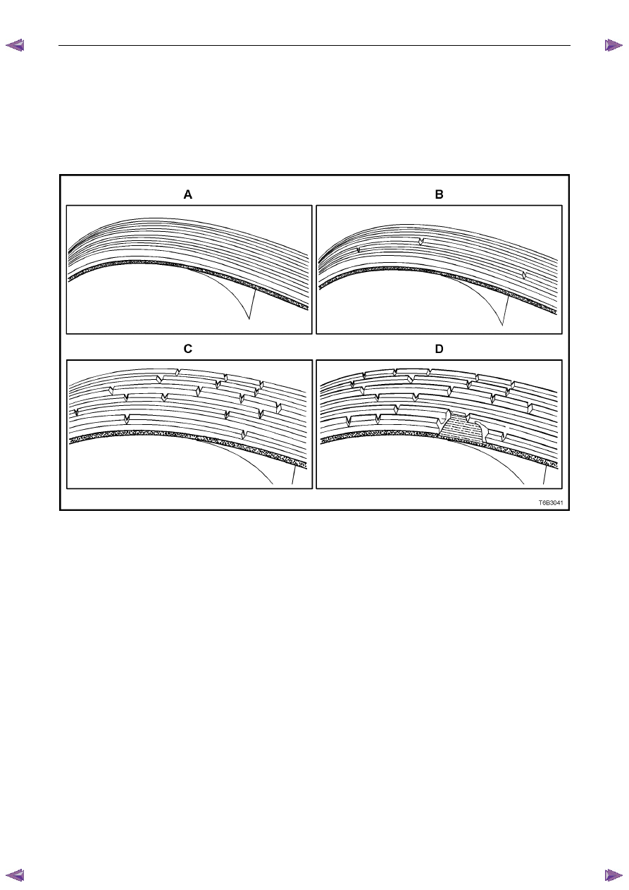
The four views in Figure 6B1 – 26 show the various stages of drive belt wear, to assist in belt replacement decisions. 

N O T E  

Condition of the belt ribs can be better assessed 
if the belt is wrapped over the coolant pump drive 
pulley. 


Figure 6B1 – 26 

Legend 

New Belt: No cracks or chunks. 

Moderately Used Belt: Few cracks, with some wear on the ribs and in the grooves. Belt replacement not required. 

Severely Used Belt: Several cracks per 30 mm. Should be replaced before chunking occurs 

Failed Belt: Separation of rib material from backing (chunking). Belt must be replaced immediately. 

Engine Cooling – V6 Engine 


Page 6B1–30 


3.6 Coolant 

Hoses 


Always wear protective safety glasses when 
working with spring type hose clamps. Failure 
to do so could result in eye injury. 

Coolant hoses are installed as shown in the following illustrations, taking note that there are a number of variants, 
depending on a specific vehicle specification. 

Hose connections should be thoroughly cleaned before installing any new hose. 

After all hoses are installed, always refill the cooling system with correct concentration of coolant, refer to 3.3 

Draining 

and Filling Cooling System and pressure test cooling system, refer to 3.7 

Pressure Testing in this Section. 


Figure 6B1 – 27 

Legend 

Radiator Hose – Upper 

Radiator Hose – Lower  

Hose Clamp – Upper Hose to Engine Outlet Housing 

Hose Clamp – Upper Hose to Radiator Inlet 

Hose Clamp – Lower Hose to Radiator Outlet 

Hose Clamp – Lower Hose to Engine Coolant Inlet Pipe 

Engine Cooling – V6 Engine 


Page 6B1–31 


3.7 Pressure 

Testing 

Coolant Filler Cap Pressure Testing 


Refer to 3.1  Service Notes in this Section, for 
important safety items. 


Allow engine to cool to ambient temperature (less than 50

° C), then remove coolant filler cap. 

Inspect and clean both sides (1) of coolant filler cap 
gasket with a wet cloth. 

N O T E  

Use only water to wet the cleaning cloth. 

Figure 6B1 – 28 

Lift centre vacuum valve. Clean and inspect the 
gasket and sealing surface under the valve (1). 

Figure 6B1 – 29 

Engine Cooling – V6 Engine 


Page 6B1–32 


Attach coolant filler cap (2) to a commercially 
available cooling system pressure tester (1), using 
the pressure cap adaptor. 

Slowly pressurise cap to 120 – 130 kPa. The cap is 
serviceable if it unloads slightly above this pressure 
range and holds pressure at 120 kPa. 

N O T E  

Should the cap fail to reach or hold the 
specified pressure, replace the cap. 


Figure 6B1 – 30 

Prior to installing coolant filler cap ensure that the 
coolant filler neck cap seating surface is clean and 
free from obstruction. 

Figure 6B1 – 31 

Cooling System Pressure Testing 


Refer to 3.1  Service Notes in this Section, for 
important safety items. 

Allow the engine to cool to ambient temperature (less than 50

° C), then remove coolant filler cap. 

Ensure that the coolant level is correct. 


Content   ..  789  790  791  792   ..