Isuzu KB P190. Service manual - part 787
 

  Index      Isuzu     Isuzu KB P190 - service and repair manual 2007 year


Search            


Content   ..  785  786  787  788   ..


Isuzu KB P190. Service manual - part 787


Engine Cooling – V6 Engine 


Page 6B1–13 


2.6 

Coolant Filler Cap 

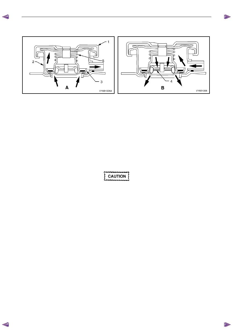
Figure 6B1 – 10 

Figure 6B1 – 11 


The pressurised coolant filler cap (1), fitted to the filler neck (2) on the coolant outlet housing, causes the cooling system 
to operate at higher than atmospheric pressure. The higher pressure raises the boiling point of the coolant, resulting in 
increased engine cooling efficiency. The coolant filler cap contains a pressure valve (3) and a vacuum (atmospheric) 
valve (4). 

Referring to view ‘A’, the pressure valve is held against its seat by a spring (5), which determines the maximum operating 
pressure of the cooling system (120 kPa ). 

Referring to view ‘B’, the vacuum valve (4) is held against its seat by a light spring and opens during cool down because 
of the drop in pressure with contraction of the coolant volume. This pressure drop over-comes the spring force and the 
vacuum valve is opened, preventing the radiator hoses from collapsing. In addition, coolant can also flow back into the 
cooling system from the coolant recovery reservoir while this valve is open maintaining a full volume of coolant within the 
engine and radiator. 


Should the radiator pressure cap require 
replacement, only fit the correct cap (with the 
correct pressure-rating) for this engine. Refer 
to the current release of Partfinder™ for this 
information. 

Engine Cooling – V6 Engine 


Page 6B1–14 


2.7 

Coolant Recovery Reservoir 

The coolant is maintained at the ideal level in the radiator by the coolant filler cap and the coolant recovery reservoir, 
resulting in increased cooling efficiency. 

The coolant recovery reservoir is located on the left-hand side front of the engine compartment, between the radiator 
support panel and air cleaner assembly. The coolant recovery reservoir is connected to the radiator overflow connection 
by a small diameter hose. 

As the engine temperature rises, the coolant is heated and expands. The fluid displaced by expansion flows from the 
radiator into the recovery reservoir. 

When the engine is turned OFF, the coolant contracts as it cools. Coolant is then drawn back into the radiator through 
the coolant filler cap atmospheric valve. 

Coolant level should be maintained between the MAX and 
MIN indicator lines on the coolant recovery reservoir, as 
shown in Figure 6B1 – 12, when the engine is cold. 

The cooling system is designed to use a coolant, DEX-
COOL® long-life coolant or equivalent to GM specification 
6277M (a mixture of ethylene glycol antifreeze and 
corrosion inhibitors and water), rather than plain water to 
maintain the integrity of the cooling system, and to prevent 
oxidation occurring within the engine. 

N O T E  

Some HFV6 Series vehicle markets call for 
DEX-COOL® long-life coolant and others for 
its equivalent, known as Extended Life Anti-
freeze Coolant, conforming to GM specification 
6277M. If in doubt regarding the correct 
coolant to be used, refer to the Owner’s 
Handbook. 


Figure 6B1 – 12 

Engine Cooling – V6 Engine 


Page 6B1–15 


2.8 

Engine Coolant Temperature Sensor 

An Engine Coolant Temperature (ECT) sensor (2) is 
mounted in the left-hand side cylinder head, just above 
the exhaust manifold. The ECT sensor is used in 
conjunction with the instrument panel temperature gauge. 
The ECT sensor generates a signal, which is used by the 
engine management system for calculation of the various 
engine management functions. 

Figure 6B1 – 13 shows the wiring harness connector (1) 
and the ECT sensor (2). 

Refer to 6C1-1 Engine Management General Information 
for further information on the ECT sensor. 


Figure 6B1 – 13 

Engine Cooling – V6 Engine 


Page 6B1–16 


3 Service 

Operations 

3.1 Service 

Notes 

Safety 


•  To avoid serious personal injury, never 

remove the coolant filler pressure cap on 
the coolant outlet housing when the 
engine is hot, even if the cooling system 
should require filling. Sudden release of 
cooling system pressure is very 
dangerous.  

•  The vehicle is fitted with an electric 

radiator cooling fan. When working around 
the engine compartment, keep clear of the 
fan as it may start without warning. 

Before removing the coolant filler cap, allow the engine to cool, then place a shop rag over the coolant filler cap and then 
slowly turn the cap anticlockwise, approximately 1½ turns, until the pressure relief position is reached. The pressure 
relief position will allow any remaining pressure within the system to escape into the coolant recovery reservoir. Continue 
to rotate the cap anticlockwise until the cap can be safely removed. 

Periodic Servicing 

The cooling system requires little attention except for maintaining the coolant to the correct level in the recovery reservoir 
and periodic servicing at the time or distance intervals as outlined in 0B Lubrication and Service. 

Periodic servicing includes: 

Checking coolant level. Refer to 3.3 

Draining and Filling Cooling System in this Section. 

Checking coolant concentration. Refer to 3.2 

Coolant Maintenance – Testing Coolant Concentration in this 

Section. 

Pressure test cooling system and coolant filler cap. Refer to 3.7  Pressure Testing in this Section. 

Tighten hose clamps and inspect all hoses. Refer to 3.6  Coolant Hoses in this Section. Replace hoses if swollen 
or deteriorated. 


Always wear protective safety glasses when 
working with spring type hose clamps. Failure 
to do so could result in eye injury. 

Clean out cooling system, refer to 3.4  Cleaning Cooling System – Cooling System Flush, in this Section and refill. 
Refer to 3.3 Draining and Filling Cooling System in this Section. 

Environmental Issues 

To reduce environmental impact and maintenance cost, whenever the coolant is drained from any engine, the service 
records are to be checked to determine when the coolant was last changed. If more than six months life is left before the 
next coolant change, then the following procedure is to be followed: 

When draining the coolant from the engine, use a clean container to hold at least 12 litres of coolant and ensure 
that the coolant is not contaminated in the draining process. 

After repairs have been completed, refill the engine cooling system with the drained coolant. 


Content   ..  785  786  787  788   ..