Isuzu KB P190. Service manual - part 666
 

  Index      Isuzu     Isuzu KB P190 - service and repair manual 2007 year


Search            


Content   ..  664  665  666  667   ..


Isuzu KB P190. Service manual - part 666


Engine Mechanical – V6 

Page 6A1–185 


Remove 

Remove the skid plate. 

Drain the radiator coolant, refer to 6B1 Engine Cooling – V6. 

Disconnect the battery negative and positive terminal, refer to 8A  Electrical Body & Chassis. 

Remove the battery from the vehicle. 

Depressurise the fuel system pressure, refer to 6C Fuel System – V6. 

Make alignment marks on the bonnet and hinges in order to return the bonnet to the exact original position. 

Remove the bonnet, refer to 2B Sheet Metal.  

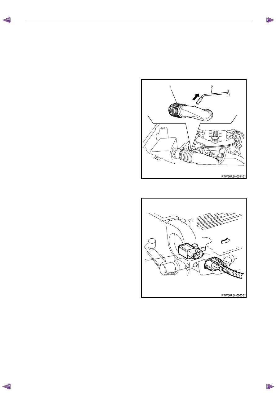
Remove the rubber hose (2) and air duct (1). 


Figure 6A1 – 317 


Disconnect the barometric sensor connector (1). 

Figure 6A1 – 318 

Engine Mechanical – V6 

Page 6A1–186 


10 

 Disconnect the vacuum booster hose (1). 


Figure 6A1 – 319 

11 

Disconnect the EVAP purge solenoid connector (1). 

Figure 6A1 – 320 

Engine Mechanical – V6 

Page 6A1–187 


Plug the fuel feed hose after removal to 
prevent dirt entering the pipe. 

12 

Disconnect the fuel pipe connector and injector 
harness connector. 

13 

Disconnect the fuel feed hose from the fuel rail (1), 
refer to 6C Fuel system. 

14 

Pull out release bar (2) of the fuel injector harness 
wiring connector (3). 

15 

Disconnect the fuel injector harness wiring connector 
from the fuel injector wiring harness (4). 


Figure 6A1 – 321 

16 

To disconnect the throttle body connector (1) the 
following procedure must be followed. 

17 

Retract the throttle body wiring connector lock (3) 
while pressing the connector latch in the direction of 
the arrow (4). 

18 

Disconnect the throttle body wiring connector (1). 

19 

Release the throttle body connector wiring harness 
from its retaining clip (5). 


Take care not to break the barbed retainer 
pin (6), when removing the harness. Should 
the pin be damaged it is vital that a new 
harness retainer be fitted. 

20 

Remove the main wiring harness retainer pin (6) from 
the intake manifold by pushing from the front to the 
rear using a suitable length of 5mm steel rod or an 
allen key. 


Figure 6A1 – 322 

21 

Disconnect the PCV fresh air tube (1) from the upper 
intake manifold mounting clip (2) and remove the 
fixing bolt (3). 


Figure 6A1 – 323 

Engine Mechanical – V6 

Page 6A1–188 


22 

Disconnect the EVAP valve outlet tube, (1) from the 
upper intake manifold (2). 

23 

Remove the four long bolts, (3) attaching the upper 
intake manifold, (2) to the cylinder heads and lower 
intake manifold. 

Figure 6A1 – 324 

23 

Remove the six bolts, (1) attaching the lower intake 
manifold (2), then remove the manifold from the 
engine. 

24 

Remove the following from the engine and engine 
compartment : 

• 

Lower intake manifold to cylinder head gasket 

• 

The Heater hose 

• 

The Air Cleaner assembly 


Figure 6A1 – 325 

25 

Remove the transmission support (1). 

26 

Remove the front and rear propeller shafts, (4WD 
Only), refer to 4C1 Front Wheel Drive and 4C2 Drive 
Line (For 4WD Vehicles). 

27 

Remove the front torsion bar springs, refer to 3C 
Suspension. 


Figure 6A1 – 326 


Content   ..  664  665  666  667   ..