Isuzu KB P190. Service manual - part 283
 

  Index      Isuzu     Isuzu KB P190 - service and repair manual 2007 year


Search            


Content   ..  281  282  283  284   ..


Isuzu KB P190. Service manual - part 283


6E-98  Engine Control System (4JH1) 

DTC P0215 (Symptom Code B) (Flash Code 52) 

Circuit Description 
The engine control module (ECM) calculates the
desired fuel injection quantity and timing using data sent
from various sensors. These desired data are sent to
the fuel injection pump control unit (PCU) via a
controller area network (CAN) communication bus. The
PCU also receives signals from the internal inputs:
pump camshaft position (CMP) sensor that is located
inside the fuel injection pump to determine the cam ring 
rotation angle and the fuel injection pump speed. The
fuel temperature (FT) sensor is internal the PCU. These 
values are used to compare the desired values sent
from the ECM then PCU determines the injection timer 
piston position and fuel injection quantity, and actuates 
timing control valve (TCV) & fuel injection solenoid
valve based on control maps in the PCU. 
The fuel injection solenoid valve is installed to the fuel
injection pump rear side. The fuel injection event is
determined by this solenoid ON/OFF command. The
fuel injection solenoid valve cuts the fuel when the
engine shutoff (ESO) solenoid valve is commanded
shutoff from the PCU. (The fuel injection solenoid valve
and engine shutoff (ESO) solenoid valve is same part. It
calls ESO solenoid valve when fuel is shutoff.) When
the ignition switch is turned OFF or commanded from 
fail-safe action, the ESO solenoid valve is commanded
shutoff to stop the engine running. If the PCU detects
that the ESO solenoid valve control circuit voltage level
from the ECM to PCU is high, this DTC will set. 
Condition for Running the DTC 

•  The ignition switch is ON. 


Condition for Setting the DTC 

•  The PCU detects high voltage condition on the 

ESO solenoid valve control circuit for longer than 1 
second when the ECM does not command shutoff.

Action Taken When the DTC Sets 

•  The ECM illuminates the malfunction indicator 

lamp (MIL) when the diagnostic runs and fails.  

Condition for Clearing the MIL/DTC 

•  The ECM turns OFF the MIL when the diagnostic 

runs and does not fail.  

•  A history DTC clears after 40 consecutive driving 

cycles without a fault. Or clear with the scan tool. 

Diagnostic Aids 

•  If an intermittent condition is suspected, refer to 

Intermittent Conditions in this section.  

Notice:  

•  Fuel injection solenoid valve is internal to the fuel 

injection pump assembly. 

•  PCU is part of the fuel injection pump assembly. 
•  If this DTC is present, engine will not start. 

 
DTC P0215 (Symptom Code B) (Flash Code 52) 
Schematic Reference: 
Engine Controls Schematics 
Connector End View Reference: Engine Controls 
Connector End Views or Engine Control Module (ECM) 
Connector End Views 


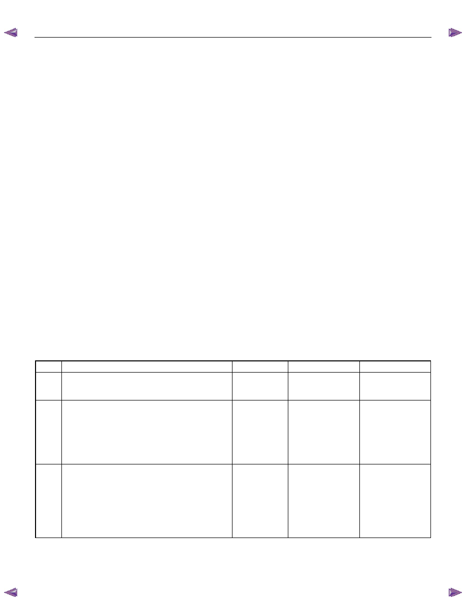
Step Action 

Value(s) 

Yes 

No 

Did you perform the Diagnostic System Check-
Engine Controls? 

 

Go to Step 2 

Go to Diagnostic 

System Check-

Engine Controls 

1.  Install the scan tool. 
2.  Turn OFF the ignition for 30 seconds. 
3.  Start the engine. If the engine does not start, 

crank over the engine. 

4. Monitor the Diagnostic Trouble Code (DTC) 

Information with the scan tool. 

Does the DTC fail this ignition? 

 

Go to Step 3 

Go to Diagnostic 

Aids 

1.  Turn OFF the ignition. 
2.  Disconnect the fuel injection pump control unit 

(PCU) harness connector. 

3.  Connect a test lamp between the engine shutoff 

(ESO) solenoid valve control signal circuit (pin 5 
of E-6 connector) and a known good ground. 

4.  Turn ON the ignition, with the engine OFF. 
Does the test lamp illuminate? 

 

Go to Step 5 

Go to Step 4 

Engine Control System (4JH1)  6E-99 

Step Action 

Value(s) 

Yes 

No 

1.  Turn OFF the ignition. 
2.  Reconnect the PCU harness connector. 
3.  Disconnect the engine control module (ECM) C-

57 harness connector. Keep the C-56 harness 
connector with connected. 

4.  Connect a test lamp between the ESO solenoid 

valve control signal circuit (pin 105 of C-57 
connector) and a known good ground. 

5.  Turn ON the ignition, with the engine OFF. 
Does the test lamp illuminate? 

 

Go to Step 6 

Go to Diagnostic 

Aids 

1.  Test the ESO solenoid valve control signal circuit 

between the ECM (pin 105 of C-57 connector) 
and the PCU (pin 5 of E-6 connector) for a short 
to battery or ignition voltage. 

2.  Repair the circuit(s) as necessary. 
Did you find and correct the condition? 

 

Go to Step 8 

Go to Step 7 

Important: The fuel injection pump must be timed to 
the engine. 
Replace the fuel injection pump. Refer to Fuel 
Injection Pump Replacement in engine mechanical 
section. 
Did you complete the replacement? 

 

Go to Step 8 

 

Important: Replacement ECM must be 
programmed. 
Replace the ECM. Refer to Engine Control Module 
(ECM) Replacement in this section. 
Did you complete the replacement? 

 

Go to Step 8 

 

1.  Reconnect all previously disconnected harness 

connector(s). 

2.  Clear the DTCs with the scan tool. 
3.  Turn OFF the ignition for 30 seconds. 
4.  Start the engine. 
5.  Monitor the DTC Information with the scan tool. 
Did the DTC fail this ignition? 

 

Go to Step 3 

Go to Step 9 

Observe the DTC Information with the scan tool. 
Are there any DTCs that you have not diagnosed? 

 

Go to Diagnostic 

Trouble Code (DTC) 

List System 

OK 


6E-100  Engine Control System (4JH1) 

DTC P0215 (Symptom Code C) (Flash Code 52) 

Circuit Description 
The engine control module (ECM) calculates the
desired fuel injection quantity and timing using data sent
from various sensors. These desired data are sent to
the fuel injection pump control unit (PCU) via a
controller area network (CAN) communication bus. The
PCU also receives signals from the internal inputs:
pump camshaft position (CMP) sensor that is located
inside the fuel injection pump to determine the cam ring 
rotation angle and the fuel injection pump speed. The
fuel temperature (FT) sensor is internal the PCU. These 
values are used to compare the desired values sent
from the ECM then PCU determines the injection timer 
piston position and fuel injection quantity, and actuates 
timing control valve (TCV) & fuel injection solenoid
valve based on control maps in the PCU. 
The fuel injection solenoid valve is installed to the fuel
injection pump rear side. The fuel injection event is
determined by this solenoid ON/OFF command. The
fuel injection solenoid valve cuts the fuel when the
engine shutoff (ESO) solenoid valve is commanded
shutoff from the PCU. (The fuel injection solenoid valve
and engine shutoff (ESO) solenoid valve is same part. It
calls ESO solenoid valve when fuel is shutoff.) When
the ignition switch is turned OFF or commanded from
fail-safe action, the ESO solenoid valve is commanded
shutoff to stop the engine running. If the ECM detects
that the engine is continuously run after the ignition
switch is OFF, this DTC will set. 
Condition for Running the DTC 

•  The ignition switch is OFF. 
•  The engine speed is lower than 1500 RPM. 
•  The vehicle speed is lower than 1.5 km/h (1 MPH).


Condition for Setting the DTC 

•  The engine speed is higher than 200 RPM within 2 

seconds after the condition for running the DTC 
are met. This indicates the PCU does not react to 
the command from the ECM and fuel cannot 
shutoff.  

Action Taken When the DTC Sets 

•  The ECM illuminates the malfunction indicator

lamp (MIL) when the diagnostic runs and fails. 

•  The ECM cuts fuel injection.  

Condition for Clearing the MIL/DTC 

•  The ECM turns OFF the MIL when the diagnostic 

runs and does not fail. 

•  A history DTC clears after 40 consecutive driving 

cycles without a fault. Or clear with the scan tool. 

Diagnostic Aids 

•  If an intermittent condition is suspected, refer to 

Intermittent Conditions in this section. 

Notice:  

•  Fuel injection solenoid valve is internal to the fuel 

injection pump assembly. 

•  PCU is part of the fuel injection pump assembly. 

 
DTC P0215 (Symptom Code C) (Flash Code 52) 
Schematic Reference: 
Engine Controls Schematics 
Connector End View Reference: Engine Controls 
Connector End Views or Engine Control Module (ECM) 
Connector End Views 


Step Action 

Value(s) 

Yes 

No 

Did you perform the Diagnostic System Check-
Engine Controls? 

 

Go to Step 2 

Go to Diagnostic 

System Check-

Engine Controls 

1.  Install the scan tool. 
2.  Turn OFF the ignition for 30 seconds. 
3.  Start the engine and let idle for 30 seconds. 
4. Monitor the Diagnostic Trouble Code (DTC) 

Information with the scan tool. 

5.  Turn OFF the engine. 
Does the DTC fail this ignition before the engine 
control module (ECM) turns OFF? 

 

Go to Step 3 

Go to Diagnostic 

Aids 

1.  Turn OFF the ignition. 
2.  Disconnect the fuel injection pump control unit 

(PCU) harness connector. 

3.  Connect a test lamp between the engine shutoff 

(ESO) solenoid valve control signal circuit (pin 5 
of E-6 connector) and battery voltage. 

4.  Turn ON the ignition, with the engine OFF. 
Does the test lamp illuminate? 

 

Go to Step 5  

Go to Step 4 

Engine Control System (4JH1)  6E-101 

Step Action 

Value(s) 

Yes 

No 

1.  Turn OFF the ignition. 
2.  Connect a DMM between the ESO solenoid valve 

control signal circuit (pin 5 of E-6 connector) and 
a known good ground. 

3.  Turn ON the ignition, with the engine OFF. 
Is the DMM voltage more than the specified value? 

10 volts 

Go to Step 7 

Go to Step 6 

1.  Test the ESO solenoid valve control signal circuit 

between the ECM (pin 105 of C-57 connector) 
and the PCU (pin 5 of E-6 connector) for a short 
to ground. 

2.  Repair the circuit(s) as necessary. 
Did you find and correct the condition? 

 

Go to Step 11 

Go to Step 10 

1.  Test the ESO solenoid valve control signal circuit 

between the ECM (pin 105 of C-57 connector) 
and the PCU (pin 5 of E-6 connector) for an open 
circuit or high resistance. 

2.  Repair the circuit(s) as necessary. 
Did you find and correct the condition? 

 

Go to Step 11 

Go to Step 8 

1.  Turn OFF the ignition. 
2.  Inspect for an intermittent, for a poor connection 

and corrosion on the ESO solenoid valve control 
signal circuit at the harness connector of the 
PCU (pin 5 of E-6 connector). 

3.  Repair the connection(s) as necessary. 
Did you find and correct the condition? 

 

Go to Step 11 

Go to Step 9 

1.  Turn OFF the ignition. 
2.  Disconnect the ECM harness connector. 
3. Inspect for an intermittent and for a poor 

connection on the ESO solenoid valve control 
signal circuit at the harness connector of the 
ECM (pin 105 of C-57 connector). 

4.  Repair the connection(s) as necessary. 
Did you find and correct the condition? 

 

Go to Step 11 

Go to Step 10 

Important: The fuel injection pump must be timed to 
the engine. 
Replace the fuel injection pump. Refer to Fuel 
Injection Pump Replacement in engine mechanical 
section. 
Did you complete the replacement? 

 

Go to Step 11 

 

10 

Important: Replacement ECM must be 
programmed. 
Replace the ECM. Refer to Engine Control Module 
(ECM) Replacement in this section. 
Did you complete the replacement? 

 

Go to Step 11 

 

11 

1.  Reconnect all previously disconnected harness 

connector(s). 

2.  Clear the DTCs with the scan tool. 
3.  Turn OFF the ignition for 30 seconds. 
4.  Start the engine. 
5.  Monitor the DTC Information with the scan tool. 
6.  Turn OFF the engine. 
Does the DTC fail this ignition before the ECM turns 
OFF? 

 

Go to Step 3 

Go to Step 12 

12 

Observe the DTC Information with the scan tool. 
Are there any DTCs that you have not diagnosed? 

 

Go to Diagnostic 

Trouble Code (DTC) 

List System 

OK 


Content   ..  281  282  283  284   ..