Isuzu KB P190. Service manual - part 182
 

  Index      Isuzu     Isuzu KB P190 - service and repair manual 2007 year


Search            


Content   ..  180  181  182  183   ..


Isuzu KB P190. Service manual - part 182


BRAKES  5C-29 

  ADJUSTMENT PROCEDURE OF SERVICE AND PARKING BRAKE 


Stick type 

All brakes are self-adjusting. 
Brakes are adjusted by repeated stepping on the brake pedal.
(After stepping on the pedal and releasing it, the rear brake 
auto-adjuster, produces a clicking sound. 
The same operation should be repeated until the sound
disappears.) 
Take the following steps after overhauling the rear brake
assembly. 
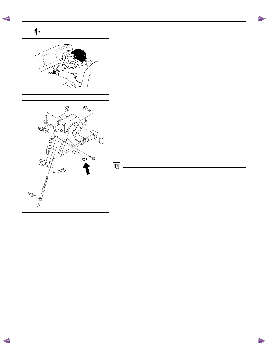
1.  Move the parking brake lever to its fully released position. 
 

311R300007 


2.  Parking cable must be loosened sufficiently. 


(Loosen the adjust nut and the lock nut.) 

3.  Repeat stepping on the brake pedal firmly and releasing it 

until the clicking sound can no longer be heard. 


If the difference between the brake drum inside diameter of

the brake shoes is adjusted to be 0.5 mm, the number of

times for depressing the brake pedal can be reduced. 

4.  Remove the drum. 


Measure the brake drum inside diameter and diameter of

the brake shoes. 

Shoe Clearance 

mm (in)

0.25 - 0.40 (0.0098 - 0.0157) 

If incorrect, check the brake auto-adjusting system. 

5.  Turn the adjuster nut so that the parking brake lever travels 

10 notches when pulled up with a force 30 kg (66 lbs.). 

6.  Make sure there is no brake drag. 


5C-30  BRAKES 


Floor mount type 

All brakes are self-adjusting. 
Brakes are adjusted by repeated stepping on the brake pedal.
(After stepping on the pedal and releasing it, the rear auto-
adjuster, in the rear brake, produces a clicking sound. 
The same operation should be repeated until the sound
disappears.) 
Take the following steps after overhauling the rear brake
assembly. 
1.  Move the parking brake lever to its fully released position. 

2.  Parking cable must be loosened sufficiently. 


(Loosen the adjust nut and the lock nut.) 

3.  Repeat stepping on the brake pedal firmly, and releasing it

until the clicking sound can no longer be heard. 


If the difference between the brake drum inside diameter of 

the brake shoes is adjusted to be 0.5 mm (0.020 in), the 

number of times for depressing the brake pedal can be

reduced. 

4.  Remove the drum. 


Measure the brake drum inside diameter and diameter of

the brake shoes. 


Shoe Clearance 

mm (in)

0.25 - 0.40 (0.010 - 0.016) 

If incorrect, check the brake auto-adjusting system. 


RUW55CSH000301 


5.  Turn the adjuster nut so that the parking brake lever travels 

7 notches when pulled up with a force 294N (30 kg / 66 lb).

6.  Make sure there is no brake dragging. 


BRAKES  5C-31 

  ADJUSTMENT PROCEDURE OF BRAKE PEDAL 


The push rod serves as the brake pedal stopper when the
pedal is fully released. 
Brake pedal height adjustment should be performed as follows.
 

RTW35CSH000601 


Brake Pedal - Height 

Measure the brake pedal height after making sure the pedal is
fully returned by the pedal return spring. 
Note: 
Pedal height (L2) must be measured after starting the
engine and increasing the revolution several times by
stepping on the accelerator pedal. 

mm (in)

  Pedal free play (L1) 

6 - 10 (0.24 - 0.39) 

M/T 

174 - 186 (6.85 - 7.32) 

Height (L2) 

A/T 

176 - 188 (6.93 - 7.40) 

Note: 
Pedal free play must be measured after turning off the
engine and stepping on the brake pedal firmly five times
or more. 
If the measured value deviates from the above range, adjust
the brake pedal as follows: 
a)  Disconnect the stop lamp switch. 

b)  Loosen the lock nut on the push rod. 

c)  Adjust the brake pedal to the specified height by rotating the

push rod in the appropriate direction. 


Lock Nut Torque 

N

⋅m (kgf⋅m/lb⋅⋅⋅⋅ft)

15 - 25 (1.5 – 2.5 / 11 - 18) 

 
d)  Install the stop lamp switch. 
 
Note: 
Pedal height (L

2

) must be 57 mm (2.24 in.) or more when 

applying about 50 kg (110.25 lbs.) of stepping force. 
 

331R300005 


How to connect the CLEVICE of the BOOSTER ROD with the
PEDAL ARM and how to adjust the PEDAL SW. 
After connecting the CLEVIS of the BOOSTER ROD to the
PEDAL ARM, adjust the PEDAL SW mounted (PDA) to the 
PEDAL BRACKET using the procedure explained below. 

1.  Set the hole of the CLEVIS of the BOOSTER & M/CYL 

ROD with the hole in the PEDAL ARM. 

2.  Enter the PIN; PUSH ROD to the PEDAL to the holes 

from the left side of the PEDAL. 

3.  Enter and fix the PIN; SNAP PIN FIX to the DITCH of 

the PIN; PUSH ROD to PEDAL from right side of the

PEDAL. 

4. Release the LOCK by turning the SWITCH counter-

clock-wise. 

5C-32  BRAKES 


5.  Pull the PEDAL ARM a little towards you so that the 

PEDAL ARM is not pushed in. 

6.  Holding the PEDAL ARM still with one hand, push in the 

whole SWITCH with the other hand until the PLUNGER 

of the SWITCH is pushed in and the SWITCH itself hits 

the RUBBER of the PEDAL ARM. 

  In this condition, turn the SWITCH clock-wise until a 

“click” sound is heard and lock it. 


By doing this the SWITCH is adjusted at 0.7

±0.5 mm 

(0.028 

± 0.020 in) clearance. 


Content   ..  180  181  182  183   ..