Isuzu KB P190. Service manual - part 173
 

  Index      Isuzu     Isuzu KB P190 - service and repair manual 2007 year


Search            


Content   ..  171  172  173  174   ..


Isuzu KB P190. Service manual - part 173


ANTI-LOCK BRAKE SYSTEM  5B-13 

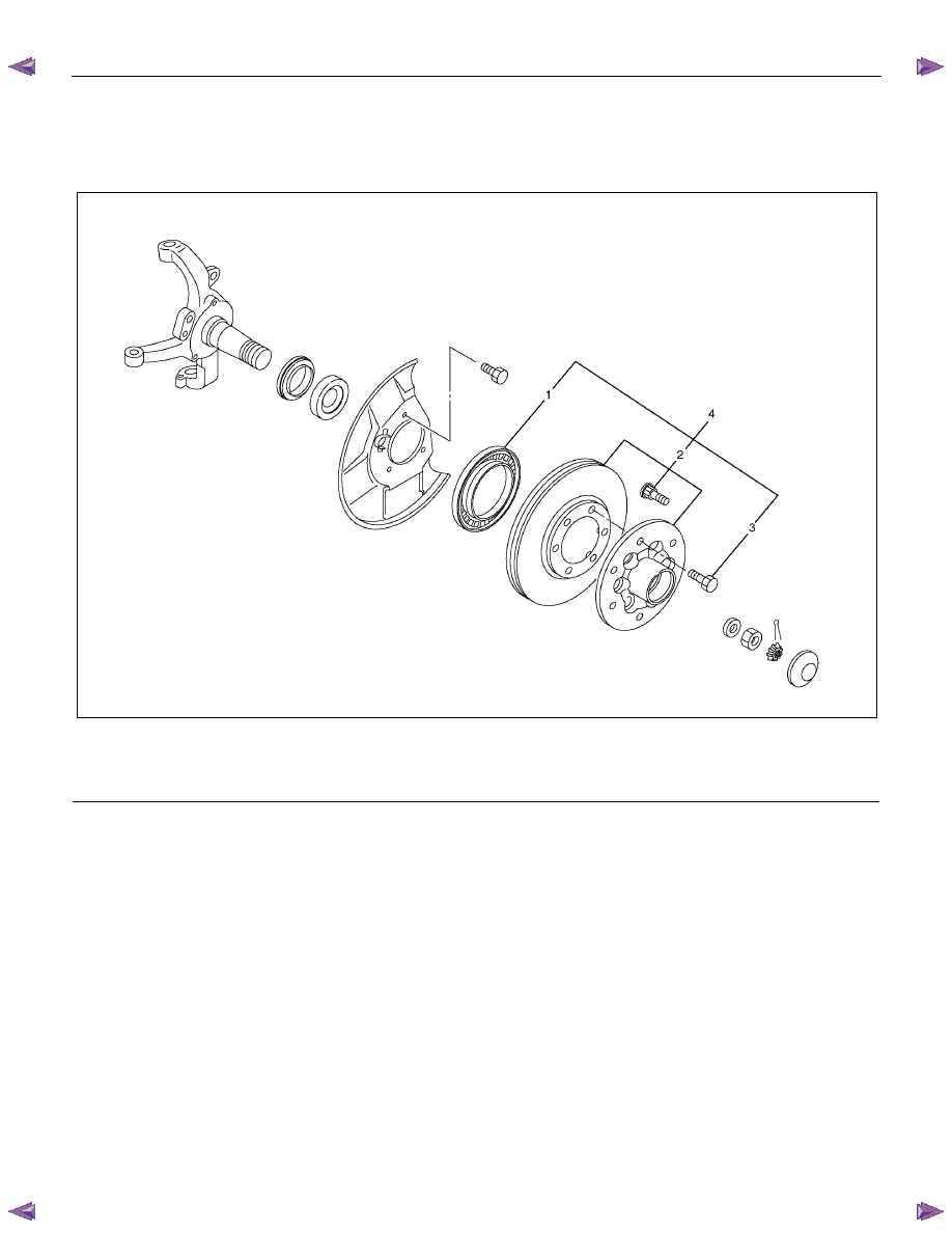
Front Sensor Rotor 

Front Sensor Rotor and Associated Parts 

411R300010

Legend 

  (1) Sensor Rotor 

  (2) Hub and Disc 


  (3) Disc Rotor fixing Bolt 

  (4) Hub and Disc Assembly 

Removal 

1.  Remove the hub and disc assembly. (Refer to the

section Front wheel Drive). 

2.  Remove two disc rotor fixing bolts on a diagonal. 

3.  Drive out the sensor rotor using a metal bar and

hammer through the two bolt holes. 
•  Discard the used sensor rotor. 

4.  Install disc rotor fixing bolts and tighten them to the

specified torque. 


Torque: 103 N

⋅m (10.5 kgf⋅m / 76 lb·ft) 


5B-14  ANTI-LOCK BRAKE SYSTEM   

411R300007

Legend 

  (1) Metal Bar 


  (2) Sensor Rotor 

Inspection and Repair 

Make all necessary adjustments, repairs or part
replacement. 

•  Check damage or powdered iron sticking to the

sensor rotor. 

•  Check play in the sensor rotor. 
•  Check a broken tooth or indentation in the sensor

rotor. 

Installation 

1.  Set a new sensor rotor. 

2. Install the new sensor rotor in the hub, using

installer 5-8840-2789-0 and grip 5-8840-0007-0. 

NOTE:  Sensor rotor is surely using a new article. 


ANTI-LOCK BRAKE SYSTEM  5B-15 

411R300006

Legend 

  (1) Hub and Disc 

  (2) Sensor Rotor 


 (3) 

Press 


3.  Measure the gap “A” at 4 points at intervals of 90

°

(degrees).  


Confirm that the gap “A” should be within the

specified range. 

Range 


Type A 

× 2 (Except High Ride 

Suspension) 

7.0 

− 7.4 mm 

(0.276 

− 0.291 in) 

× 4 

× 2 High Ride Suspension 

7.2 

− 7.6 mm 

(0.283 

− 0.299 in) 


411R300016

4. Install the hub and disc assembly. (Refer to the 

section Front wheel Drive). 


5B-16  ANTI-LOCK BRAKE SYSTEM   

Rear Sensor Rotor 

Rear Sensor Rotor and Associated Parts 


RTW55BLF000101

 
Legend 

  (1) Axle Shaft Assembly with Brake 

  (2) Sensor Rotor 


 (3) 

Front 

Removal 

1.  Remove the axle shaft assembly with brake. (Refer

to the section Rear Axle) 


Content   ..  171  172  173  174   ..