Isuzu KB P190. Service manual - part 84
 

  Index      Isuzu     Isuzu KB P190 - service and repair manual 2007 year


Search            


Content   ..  82  83  84  85   ..


Isuzu KB P190. Service manual - part 84


3C-16  FRONT SUSPENSION 

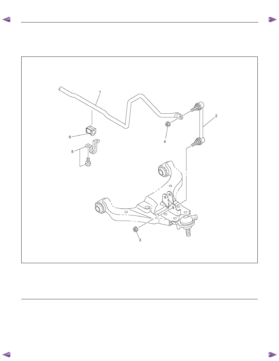
Stabilizer Bar 

Stabilizer Bar and Associated Parts 


RTW340LF000901 

Legend 

  (1) Stabilizer Bar 

  (2) Link 

  (3) Link Nut 


  (4) Link Nut 

  (5) Bracket and Bolt 

  (6) Rubber Bushing 


Removal 

1. Raise the vehicle and support the frame with 

suitable safety stands. 

2.  Remove wheel and tire assembly. Refer to Wheel

Replacement in this section. 


3.  Remove link nut. 

CAUTION: Be careful not to damage the ball joint 
boot. 

4. Remove link. 

5.  Remove bracket and bolt. 

6.  Remove stabilizer bar. 

7.  Remove rubber bushing. 

FRONT SUSPENSION  3C-17 

Inspection and Repair 

Make the necessary adjustments or parts replacement
if wear, damage, corrosion or any other abnormal
condition is found during inspection. 

Check the following parts: 

•  Stabilizer bar 
•  Rubber bushing 
•  Link ball joint  

Installation 

1.  Install rubber bushing. 

2.  Install stabilizer bar. 

3. Install bracket and bolt then tighten it to the

specified torque. 

Torque: 25 N

⋅⋅⋅⋅m (2.5 kgf⋅⋅⋅⋅m/18 lbft) 

4. Install link. 

5. Install link nut, then tighten it to the specified

torque. 

Torque: 50 N

⋅⋅⋅⋅m (5.1 kgf⋅⋅⋅⋅m/37 lbft) 


3C-18  FRONT SUSPENSION 

Knuckle 

Knuckle and Associated Parts 


450R300037 

Legend 

  (1) Nut and Cotter Pin 

  (2) Back Plate 

  (3) Nut and Cotter Pin 


  (4) Nut and Cotter Pin 

  (5) Knuckle 

  (6) Bolt 


Removal 

1. Raise the vehicle and support the frame with

suitable safety stands. 

2.  Remove wheel and tire assembly. Refer to Wheel

in this section. 


3.  Remove the brake caliper. Refer to Disc Brakes in 

Brake section. 

4. Remove the hub assembly. Refer to Front Hub 

and Disk in this section. 

5. Remove tie-rod end from the knuckle. Refer to 

Power Steering Unit in Steering section. 


FRONT SUSPENSION  3C-19 

6.  Remove the stabilizer link nuts. Right and left. 

7.  Remove the wheel speed sensor from the knuckle.

8.  Remove back plate. 

9.  Remove lower ball joint by using remover 5-8840-

2017-0. 

CAUTION: Be careful not to damage the ball joint
boot. 


P1010009

10. Remove upper ball joint by using remover 5-8840-

2017-0. 

CAUTION: Be careful not to damage the ball joint
boot. 


P1010011

11. Remove  knuckle. 


Inspection and Repair 

Make the necessary adjustments or parts replacement 
if wear, damage, corrosion or any other abnormal
condition is found during inspection. 

Check the following parts: 

•  Knuckle 
•  Knuckle arm 

Installation 

1.  Install knuckle assembly. 

2.  Install upper ball joint and tighten the nut to the 

specified torque, with just enough additional torque 

to align cotter pin holes. Install new cotter pin. 

Torque: 98 N

⋅⋅⋅⋅m (10.0 kgf⋅⋅⋅⋅m/72 lbft) 

3. Install lower ball joint and tighten the nut to the 

specified torque, with just enough additional torque 

to align cotter pin holes. Install new cotter pin. 

Torque: 147 N

⋅⋅⋅⋅m (15.0 kgf⋅⋅⋅⋅m/108 lbft) 

4.  Install back plate. 

5.  Install wheel speed sensor. 

6.  Install stabilizer link nut. Right and left. 


Content   ..  82  83  84  85   ..