Honda Accord Hybrid (2019 year). Manual - part 38
 

  Index      Honda     Honda Accord Hybrid - service manual 2019 year in english


Search            


Content   ..  36  37  38  39   ..


Honda Accord Hybrid (2019 year). Manual - part 38


uu

Replacing Light Bulbs

u

Headlight Bulbs

592

Main

tenan

ce

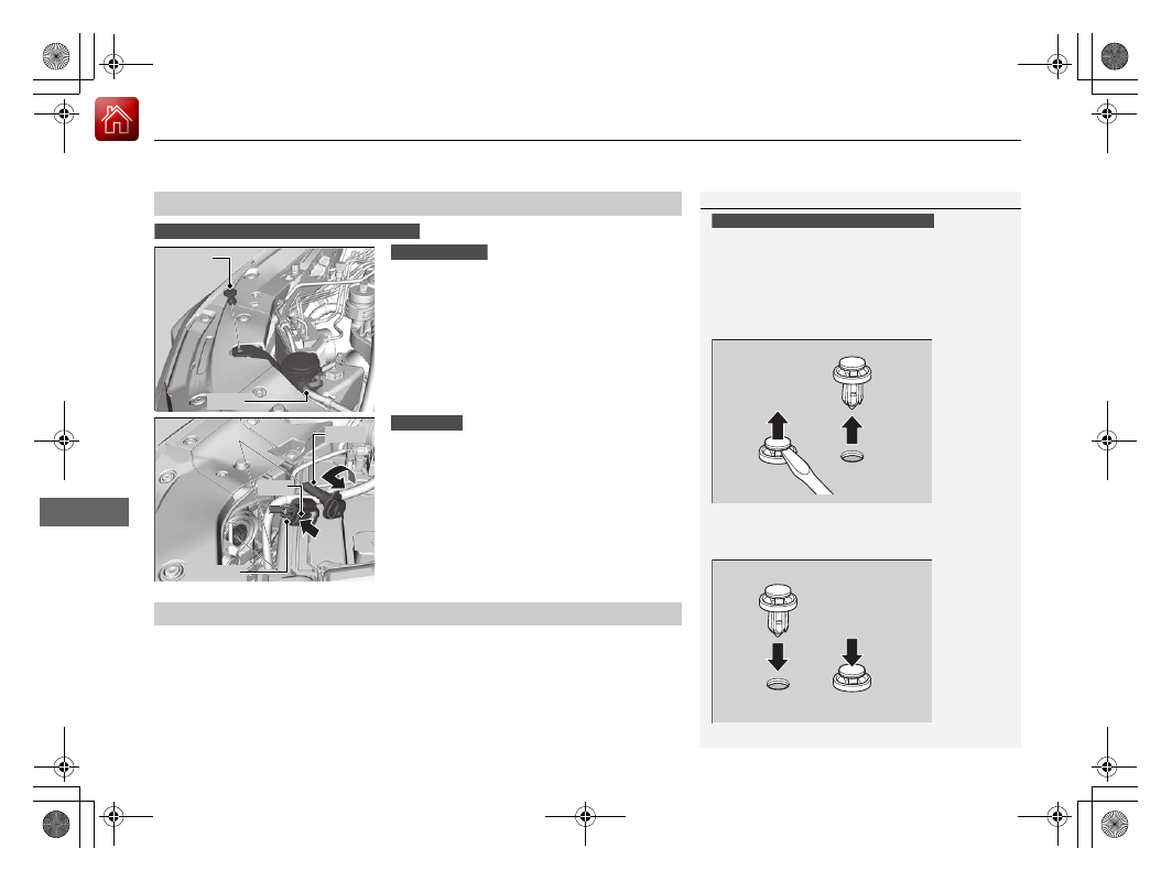
1. Remove the hose and the holding clip using 

a flat-tip screwdriver, then remove the 
upper part of the window washer reservoir.

u

Check the amount of window washer 
fluid is below the upper part of the 
window washer reservoir and remove it.

2. Push the tab to remove the coupler.
3. Rotate the old bulb counter-clockwise to 

remove.

4. Insert a new bulb into the headlight 

assembly and turn it clockwise.

5. Insert the coupler into the connector of the 

bulb.

Low beam headlights are LED type. Have an authorized Honda dealer inspect and 
replace the light assembly.

High Beam Headlights

1

High Beam Headlights

High beam headlights are LED type. Have an 
authorized Honda dealer inspect and replace the light 
assembly.

When removing the clip, insert a flat-tip screwdriver, 
then lift and remove the clip.

Insert the clip with the pin raised, and push until it is 
flat.

Models with LED high beam headlights

Push until the pin 
is flat.

Models with halogen high beam headlights

Holding 
clip

Hose

Passenger side

Tab

Coupler

Bulb

Both sides

Low Beam Headlights

593

uu

Replacing Light Bulbs

u

Fog Lights

*

Main

tenan

ce

Fog Lights

*

Fog lights are LED type. Have an authorized Honda dealer inspect and replace the 
light assembly.

Parking/Daytime Running Lights

Parking/daytime running lights are LED type. Have an authorized Honda dealer 
inspect and replace the light assembly.

Front Turn Signal Lights

Front turn signal lights are LED type. Have an authorized Honda dealer inspect and 
replace the light assembly.

Front Side Marker Lights

Front side marker lights are LED type. Have an authorized Honda dealer inspect and 
replace the light assembly.

Side Turn Signal/Emergency Indicator Lights

*

Door mirror side turn lights are LED type. Have an authorized Honda dealer inspect 
and replace the light assembly.

* Not available on all models

594

uu

Replacing Light Bulbs

u

Brake Lights, Taillights, Rear Side Marker Lights, and Rear Turn Signal Light Bulbs

Main

tenan

ce

Brake Lights, Taillights, Rear Side Marker Lights, and 
Rear Turn Signal Light Bulbs

When replacing, use the following bulbs.

1. Pry on the edge of the cover using a flat-tip 

screwdriver to remove the cover.

u

Wrap the flat-tip screwdriver with a cloth 
to prevent scratches.

2. Remove the bolts.
3. Pull the light assembly out of the rear pillar.

Brake Light: LED
Taillight: LED
Rear Side Marker Light: LED
Rear Turn Signal Light: 21 W (Amber)

1

Brake Lights, Taillights, Rear Side Marker Lights, and Rear Turn 
Signal Light Bulbs

Brake lights, taillights, and rear side marker lights are 
LED type. Have an authorized Honda dealer inspect 
and replace the light assembly.

Cover

Bolts

595

uu

Replacing Light Bulbs

u

Brake Lights, Taillights, Rear Side Marker Lights, and Rear Turn Signal Light Bulbs

Main

tenan

ce

4. Turn the socket counter-clockwise and 

remove it.

5. Push and turn the old bulb clockwise and 

remove it, and insert a new bulb.

Bulb

Socket

596

uu

Replacing Light Bulbs

u

Taillights, Brake Lights

*

, and Back-Up Light Bulbs

Main

tenan

ce

Taillights, Brake Lights

*

, and Back-Up Light Bulbs

When replacing, use the following bulbs.

1. Remove the holding clips using a flat-tip 

screwdriver, then pull the lining back.

2. Turn the socket counter-clockwise and 

remove it.

3. Remove the old bulb and insert a new bulb.

Taillight: LED
Brake Light

*

: LED

Back-Up Light: 16 W

1

Taillights, Brake Lights

*

, and Back-Up Light Bulbs

Taillights and brake lights

*

 are LED type. Have an 

authorized Honda dealer inspect and replace the light 
assembly.

When removing the clip, insert a flat-tip screwdriver, 
then lift and remove the clip.

Insert the clip with the pin raised, and push until it is 
flat.

Clip

Push until the 
pin is flat.

Holding Clip

Bulb

Socket

Driver side

* Not available on all models

597

uu

Replacing Light Bulbs

u

Taillights, Brake Lights

*

, and Back-Up Light Bulbs

Main

tenan

ce

2. Turn the socket clockwise and remove it.
3. Remove the old bulb and insert a new bulb.

Bulb

Socket

Passenger side

598

uu

Replacing Light Bulbs

u

Rear License Plate Light

Main

tenan

ce

Rear License Plate Light

Rear license plate light is LED type. Have an authorized Honda dealer inspect and 
replace the light assembly.

High-Mount Brake Light

High-mount brake light is LED type. Have an authorized Honda dealer inspect and 
replace the light assembly.

599

Continued

Main

tenan

ce

Checking and Maintaining Wiper Blades

Checking Wiper Blades

If the wiper blade rubber has deteriorated, it will leave streaks and the hard surfaces 
of the blade may scratch the window glass.

Changing the Wiper Blade Rubber

1. Set the power mode to VEHICLE OFF.
2. While holding the wiper switch in the 

MIST position, set the power mode to ON, 
then to VEHICLE OFF.

u

Both wiper arms are set to the 
maintenance position as shown in the 
image.

3. Lift the driver side wiper arm first, then the 

passenger side.

1

Changing the Wiper Blade Rubber

NOTICE

Avoid dropping the wiper arm onto the windshield, it 
may damage the wiper arm and/or the windshield.

600

uu

Checking and Maintaining Wiper Blades

u

Changing the Wiper Blade Rubber

Main

tenan

ce

4. Press and hold the tab, then slide the 

holder off the wiper arm.

5. Pull the end of the wiper blade in the 

direction of the arrow in the image until it 
is out of the holder’s end cap.

6. Pull the wiper blade in the opposite 

direction to slide it out of the holder.

Tab

Blade

End Cap At 
The Bottom

Blade

Holder

601

uu

Checking and Maintaining Wiper Blades

u

Changing the Wiper Blade Rubber

Main

tenan

ce

7. Insert the flat side of the new wiper blade 

onto the bottom part of the holder. Insert 
the blade all the way.

8. Install the end of the wiper blade into the 

cap.

9. Slide the holder onto the wiper arm until it 

locks.

10. Lower the passenger side wiper arm first, 

then the driver side.

11. Set the power mode to ON and hold the 

wiper switch in the MIST position until 
both wiper arms return to the standard 
position.

Holder

Blade

Cap

602

Main

tenan

ce

Checking and Maintaining Tires

Checking Tires

To safely operate your vehicle, your tires must be of the proper type and size, in 
good condition with adequate tread, and properly inflated.

Inflation guidelines

Properly inflated tires provide the best combination of handling, tread life, and 
comfort. Refer to the driver’s doorjamb label or specifications page for the specified 
pressure.

Underinflated tires wear unevenly, adversely affect handling and fuel economy, and 
are more likely to fail from overheating.

Overinflated tires make your vehicle ride harshly, are more prone to road hazards, 
and wear unevenly.

Every day before you drive, look at each of the tires. If one looks lower than the 
others, check the pressure with a tire gauge.

At least once a month or before long trips, use a gauge to measure the pressure in 
all tires. Even tires in good condition can lose 1–2 psi (10–20 kPa, 0.1–0.2 kgf/cm

2

per month.

Inspection guidelines

Every time you check inflation, also examine the tires and valve stems. Look for:
• Bumps or bulges on the side or in the tread. Replace the tire if you find any cuts, 

splits, or cracks in the side of the tire. Replace it if you see fabric or cord.

• Remove any foreign objects and inspect for air leaks.
• Uneven tread wear. Have a dealer check the wheel alignment.
• Excessive tread wear.

Wear Indicators P. 607

• Cracks or other damage around valve stem.

1

Checking Tires

Measure the air pressure when tires are cold. This 
means the vehicle has been parked for at least three 
hours, or driven less than 1 mile (1.6 km). If 
necessary, add or release air until the specified 
pressure is reached.

If checked when hot, tire pressure can be as much as 
4–6 psi (30–40 kPa, 0.3–0.4 kgf/cm

2

) higher than if 

checked when cold.

Whenever tire pressure is adjusted, you must 
calibrate the TPMS.

TPMS Calibration P. 480

Have a dealer check the tires if you feel a consistent 
vibration while driving. New tires and any that have 
been removed and reinstalled should be properly 
balanced.

3

WARNING

Using tires that are excessively worn or 
improperly inflated can cause a crash in 
which you can be seriously hurt or killed.

Follow all instructions in this owner’s 
manual regarding tire inflation and 
maintenance.

603

uu

Checking and Maintaining Tires

u

Tire and Loading Information Label

Continued

Main

tenan

ce

Tire and Loading Information Label

The label attached to the driver’s doorjamb provides necessary tire and loading 
information.

Tire Labeling

The tires that came on your vehicle have a 
number of markings. Those you should be 
aware of are described as shown.

Whenever tires are replaced, they should be replaced with tires of the same size.

1

Tire and Loading Information Label

The tire and loading information label attached to the 
driver’s doorjamb contains:

a

The number of people your vehicle can carry.

b

The total weight your vehicle can carry. Do not 
exceed this weight.

c

The original tire sizes for front and rear.

d

The proper cold tire pressure for front and rear.

Label 
Example

Example

Tire Size

Tire 
Identification 
Number (TIN)

Maximum 
Tire Load

Maximum 
Tire Pressure

Tire Size

Tire Sizes

1

Tire Sizes

Following is an example of tire size with an 
explanation of what each component means.
225/50R17 94V
225: Tire width in millimeters.
50: Aspect ratio (the tire’s section height as a 
percentage of its width).
R: Tire construction code (R indicates radial).
17: Rim diameter in inches.
94: Load index (a numerical code associated with the 
maximum load the tire can carry).
V: Speed symbol (an alphabetical code indicating the 
maximum speed rating).

uu

Checking and Maintaining Tires

u

Tire Labeling

604

Main

tenan

ce

The tire identification number (TIN) is a group of numbers and letters that look like 
the example in the side column. TIN is located on the sidewall of the tire.

Cold Tire Pressure – The tire air pressure when the vehicle has been parked for at 
least three hours or driven less than 1 mile (1.6 km).
Load Rating – Means the maximum load that a tire is rated to carry for a given 
inflation pressure.
Maximum Inflation Pressure – The maximum tire air pressure that the tire can 
hold.
Maximum Load Rating – Means the load rating for a tire at the maximum 
permissible inflation pressure for that tire.
Recommended Inflation Pressure – The cold tire inflation pressure 
recommended by the manufacturer.
Treadwear Indicators (TWI) – Means the projections within the principal grooves 
designed to give a visual indication of the degrees of wear of the tread.

Tire Identification Number (TIN)

Glossary of Tire Terminology

1

Tire Identification Number (TIN)

DOT B97R FW6X 2209
DOT: This indicates that the tire meets all 
requirements of the U.S. Department of 
Transportation.
B97R: Manufacturer’s identification mark.
FW6X: Tire type code.
22 09: Date of manufacture.

Year
Week

605

uu

Checking and Maintaining Tires

u

DOT Tire Quality Grading (U.S. Vehicles)

Continued

Main

tenan

ce

DOT Tire Quality Grading (U.S. Vehicles)

The tires on your vehicle meet all U.S. Federal Safety 
Requirements. All tires are also graded for treadwear, traction, 
and temperature performance according to Department of 
Transportation (DOT) standards. The following explains these 
gradings.

Quality grades can be found where applicable on the tire sidewall 
between tread shoulder and maximum section width.

The treadwear grade is a comparative rating based on the wear 
rate of the tire when tested under controlled conditions on a 
specified government test course. For example, a tire graded 150 
would wear one and one-half (1 1/2) times as well on the 
government course as a tire graded 100. The relative performance 
of tires depends upon the actual conditions of their use, however, 
and may depart significantly from the norm due to variations in 
driving habits, service practices and differences in road 
characteristics and climate.

Uniform Tire Quality Grading

Treadwear

1

Uniform Tire Quality Grading

For example:
Treadwear 200
Traction AA
Temperature A

All passenger car tires must conform 
to Federal Safety Requirements in 
addition to these grades.

uu

Checking and Maintaining Tires

u

DOT Tire Quality Grading (U.S. Vehicles)

606

Main

tenan

ce

The traction grades, from highest to lowest, are AA, A, B, and C. 
Those grades represent the tire’s ability to stop on wet pavement 
as measured under controlled conditions on specified 
government test surfaces of asphalt and concrete. A tire marked 
C may have poor traction performance.

The temperature grades are A (the highest), B, and C, 
representing the tire’s resistance to the generation of heat and its 
ability to dissipate heat when tested under controlled conditions 
on a specified indoor laboratory test wheel. Sustained high 
temperature can cause the material of the tire to degenerate and 
reduce tire life, and excessive temperature can lead to sudden tire 
failure. The grade C corresponds to a level of performance which 
all passenger car tires must meet under the Federal Motor Vehicle 
Safety Standard No. 109. Grades B and A represent higher levels 
of performance on the laboratory test wheel than the minimum 
required by law.

Traction

Temperature

1

Traction

Warning: The traction grade 
assigned to this tire is based on 
straight-ahead braking traction tests, 
and does not include acceleration, 
cornering, hydroplaning, or peak 
traction characteristics.

1

Temperature

Warning: The temperature grade for 
this tire is established for a tire that is 
properly inflated and not 
overloaded. Excessive speed, 
underinflation, or excessive loading, 
either separately or in combination, 
can cause heat buildup and possible 
tire failure.

607

uu

Checking and Maintaining Tires

u

Wear Indicators

Main

tenan

ce

Wear Indicators

The groove where the wear indicator is 
located is 1/16 inch (1.6 mm) shallower than 
elsewhere on the tire. If the tread has worn so 
that the indicator is exposed, replace the tire. 
Worn out tires have poor traction on wet 
roads.

Tire Service Life

The life of your tires is dependent on many factors, including driving habits, road 
conditions, vehicle loading, inflation pressure, maintenance history, speed, and 
environmental conditions (even when the tires are not in use).

In addition to regular inspections and inflation pressure maintenance, it is 
recommended that you have annual inspections performed once the tires reach five 
years old. All tires should be removed from service after 10 years from the date of 
manufacture, regardless of their condition or state of wear.

1

Checking Tires

High speed driving
We recommend that you do not drive faster than the 
posted speed limits and conditions allow. If you drive 
at sustained high speeds (over 99 mph or 160 km/h), 
adjust the cold tire pressures as shown below to 
avoid excessive heat build up and sudden tire failure.

Tire Size

225/50R17 94V

Pressure

Front: 35 psi (240 kPa, 2.4 kgf/cm

2

)

Rear: 33 psi (230 kPa, 2.3 kgf/cm

2

)

Example of a Wear 
Indicator mark


Content   ..  36  37  38  39   ..