Harley Davidson 2008 Touring Models. Electrical Diagnostics Manual - page 19
HOME
Throttle Control Actuator: DTC P2100, P2101, P2102, P2103
Is DTC
P2101 set?
YES
NO
Disconnect the Throttle Control Actuator
Are any Throttle Position Sensor
(TCA) connector [211]. Test for
(TPS) or Twist Grip Sensor
continuity between terminal “2” and
(TGS) codes set?
terminal “3” of connector [211A].
Is continuity present?
YES
NO
YES
NO
Inspect the throttle plate
Refer to applicable
for an interference or
Disconnect the ECM connector
DTC.
binding.
[78]. Test for short to voltage on
Replace TCA.
Was trouble found?
terminal “29” (BK/O) (+) to ground
(-) and terminal “30” (BK/PK) (+)
to ground (-) on connector [78B].
Is voltage present?
YES
NO
Repair
Replace
YES
NO
interference.
TCA.
Repair short to
Test for open or short to ground on
voltage on
terminal “29” (BK/O) (+) to ground (-)
appropriate wire.
and terminal “30” (BK/PK) (+) to ground
(-) on connector [78B].
Is open or short to ground present?
YES
NO
Repair open or short to
Replace ECM.
ground on appropriate wire.
fc01316_en
4-186 2008 Touring Diagnostics: Engine Management
HOME
DTC P2105
4.40
Initially, the ECM commands the fuel pump and fuel injectors
GENERAL
to be disabled until the actual fault is cleared.
The Throttle Actuation Control (TAC) System uses DTC P2105
as a vehicle safety device. It provides a forced shut down of
Table 4-72. Code Description
the engine when the performance of the Throttle Control
Actuator (TCA) cannot be verified. Refer to Table 4-72.
DTC
DESCRIPTION
P2105
TAC system forced engine shutdown
DIAGNOSTICS
Diagnostic Notes
Refer to and conduct diagnostics as identified on the flow chart.
2008 Touring Diagnostics: Engine Management 4-187
HOME
TAC System Forced Engine Shutdown: DTC P2105
Turn the Ignition switch on. Verify code is
present. Turn the Ignition switch off. Turn
the Ignition switch on.
Is DTC P2105 present?
YES
NO
Are any of the following DTCs present?
Code was properly
P0605, P1600, P2100
cleared.
YES
NO
Is DTC P1511 set along
Refer to priority chart and go to
with either code P0108,
appropriate DTC diagnostics.
P0651 or P01514?
YES
NO
Refer to priority chart and go to
Replace ECM.
appropriate DTC diagnostics.
Clear codes using speedometer self diagnostics.
See 4.6 SPEEDOMETER SELF DIAGNOSTICS.
Confirm proper operation with no check engine lamp.
fc01333_en
4-188 2008 Touring Diagnostics: Engine Management
HOME
DTC P2107
4.41
to an internal over-temperature shutdown or a power supply
GENERAL
failure.
Refer to Table 4-73. The Throttle Actuation Control (TAC)
System sets DTC P2107 to identify faults with the ECM due
Table 4-73. Code Description
DTC
DESCRIPTION
P2107
TAC system module processor - internal
fault
ed01260
1
2
3
4
19
5
18
6
7
17
8
16
9
15
14
13
12
11
10
1. Accessory
11. Spare
2. Battery
12. Lights
3. P&A
13. Headlamp
4. Radio power/Siren (if equipped)
14. ABS (if equipped)
5. ECM power
15. Brake relay
6. System relay
16. Instruments
7. Start relay
17. Fuel pump
8. Engine control
18. Radio memory (if equipped)
9. MAXIFUSE
19. Brake/Cruise
10. Ignition
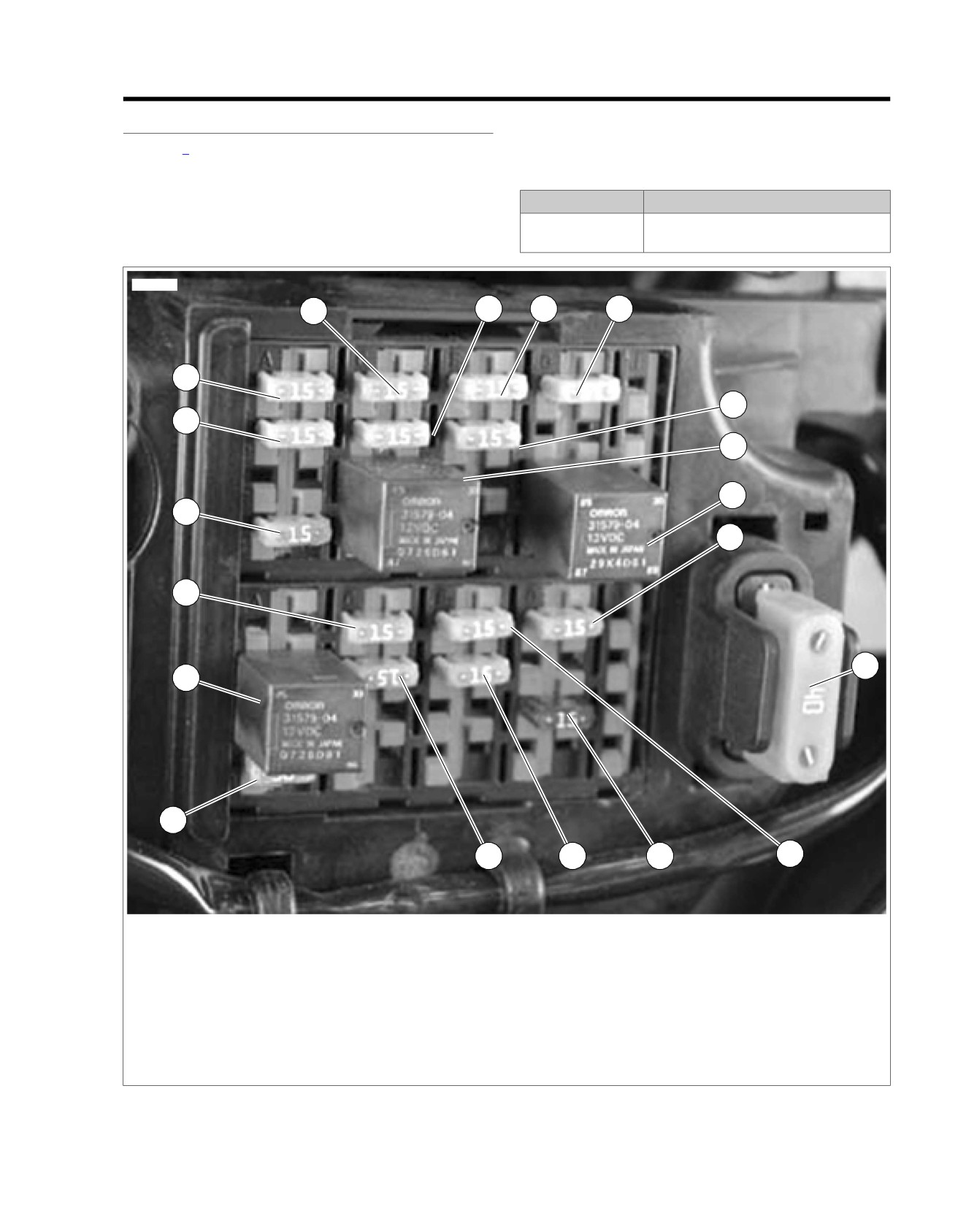
Figure 4-78. Fuse and Relay Locations
2008 Touring Diagnostics: Engine Management 4-189
HOME
ECM. However, poor connections and high resistance on
DIAGNOSTICS
(Y/GN) 12V power wire can also cause this code to set. If the
Diagnostic Tips
code does not reset after it is cleared, check for an intermittent
poor connection on this wire.
This code is usually set due to an internal problem with the
Twist Grip Sensor
em00093
Engine
Throttle
Temp.
TMAP
Control
Crank Position
Switch
Sensor
Actuator
Sensor
[224A]
654321
[224B]
654321
Data
[90A]
Link
A
B
[80A]
1234
[211A]
6
5
4
3
2
1
[90B]
A
B
1234
6
5
4
3
2
1
[79A]
1 2
12
3
4
[80B]
[211B]
1 2
[91A]
[204A]
6
54321
[79B]
[141A]
(GY)
654321
[204B]
FUEL
PUMP
AB CD
AB CD
Fuel Pump
Assembly In Tank
[141B]
Fuel Tank
[13B]
Harness
1234
1234
[13A]
Electronic
Control
[78A]
[78B]
Fuel
Module
Pump
87(5)
30(3)
Fuse
To
fuel
Purge solenoid
20
20
86(1)
15 Amp
gauge
Exhaust actuator
21
21
V/O
85(2)
[83B]
[83A]
Ignition Coil
System
Rear injector
23
23
GN/GY
MAXIFUSE
MAP sensor input
24
24
V/W
Relay
40 Amp
Brake switch
25
25
R/BE
Y/GN
A
A
Power
GY/BE
B
B
Ion sense
[5B]
System relay enable
27
27
GN/O
Y/BE
C
C
Coil rear
B A
Front injector
28
28
W/Y
BE/O
D
D
Coil front
Throttle by wires HI
29
29
BK/O
ECM
Throttle by wires LO
30
30
BK/PK
Fuse
BE/GY
(+)
(-)
Ion sense
33
33
GY/BE
Cruise/Resume/Accelerate
34
34
15 Amp
Cruise enable
35
35
Throttle pos. sensor-2
36
36
BN/R
[84B]
[84A]
Throttle pos. sensor-1
37
37
BN/V
Battery
Y/GN
A
A
Front
Exhaust feedback
38
38
V/BE
Twist grip sensor-2
39
39
V/Y
W/Y
B
B
Injector
[33B]
Vehicle speed input
40
40
W/GN
Ignition
[85B] [85A]
Fuse
Crank position sensor
43
43
BK
1
15 Amp
R
2
Rear O2 sensor
46
46
PK/GN
Y/GN
A
A
Rear
R/BK
3
GN/GY
B
B
Injector
Intake air temperature
49
49
LGN/Y
Ignition
5V sensor power-1
50
50
BN/O
Switch
Engine temperature
51
51
PK/Y
[95B] [95A]
Engine
[33A]
12V power
52
52
Y/GN
Control
Rear coil
53
53
Y/BE
Fuse
Front coil
54
54
BE/O
GY/Y
Y/GN
15 Amp
Jiffy stand sensor
56
56
GN/BN
Purge
Twist grip sensor-1
59
59
BE/GN
Solenoid
5V sensor ground-1
61
61
BK/W
5V sensor ground-2
62
62
BK/GY
[65B] [65A]
Crank pos. sensor (+)
63
63
R
Vehicle speed ground
64
64
BK/Y
BN/O
Vehicle
Front O2 sensor
66
66
PK/O
W/GN
Speed
BK/Y
Sensor
5V sensor power-1
68
68
R/W
Serial data
69
69
LGN/V
BK/W
12V battery
71
71
BE/GY
12V stop switch
72
72
W/BK
Ground
73
73
BK/GN
[1A]
3
6
Main
[1B]
3
6
Harness
To
accessory
fuse
[22B]
3
4
Right Hand
[121B]
[22A]
3
4
Controls
[137B]
[138B]
[133B]
[179B]
[121A]
12
12
123
54321
Rear
Rear
Front
Jiffy Stand
Active
Stop Lamp
O2 Sensor
O2 Sensor
Switch
Exhaust
Switch
(HDI only)
(HDI only)
Engine Stop Switch
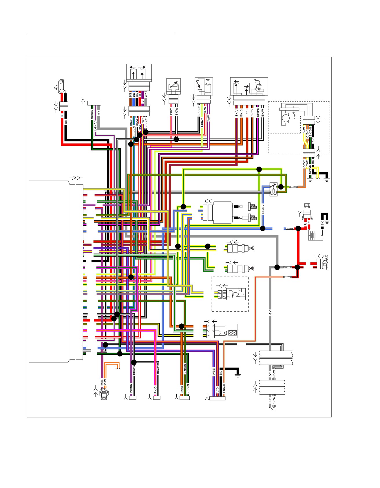
Figure 4-79. System Relay Circuit (FLHX, FLHT/C/U, FLTR)
4-190 2008 Touring Diagnostics: Engine Management

HOME
Table 4-74. Wire Harness Connectors
NO.
DESCRIPTION
TYPE
LOCATION
[1]
Main to interconnect harness
16-place Molex (black)
Inner fairing (right radio support
bracket)
[5]
MAXIFUSE
2-place Packard
Under left side cover
[13]
Fuel tank harness
4-place Multilock
Behind fuel tank (under seat)
[22]
Right handlebar switches
12-place Molex (black)
Inner fairing (fork stem nut lock plate)
[33]
Ignition switch
3-place Packard
Inner fairing (under radio)
[65]
Vehicle Speed Sensor (VSS)
3-place Delphi
Top of transmission case (under
starter)
[78]
Electronic Control Module (ECM)
73-place Delphi
Under seat
[79]
Crankshaft Position (CKP) sensor
2-place Mini-Deutsch
Electrical caddie at bottom of lower
frame crossmember
[80]
T
emperature Manifold Absolute Pres-
4-place Delphi
Top of induction module
sure (TMAP) sensor
[83]
Ignition coil
4-place Delphi
Below fuel tank (left side)
[84]
Front injector
2-place Delphi
Below fuel tank (left side)
[85]
Rear injector
2-place Delphi
Below fuel tank (left side)
[90]
Engine
Temperature (ET) sensor
2-place Delphi
Back of front cylinder (left side)
[91]
Data link connector
4-place Deutsch
Under left side cover
[95]
Purge solenoid
2-place Delphi
Below fuel tank (left side)
[121]
Rear brake light switch
Spade terminal
Bottom of rear frame downtub (right
side)
[133]
Jiffy Stand Sensor
3-place Molex (black)
Domestic (not used): Electrical caddie
bottom of lower crossmember
HDI: Electrical caddie at bottom of
lower frame crossmember
[137]
O
sensor rear exhaust header
2-place Amp (T
yco)
Under chrome starter cover
2
[138]
O
sensor front exhaust header
2-place Amp (Tyco)
Back of cross brace front frame down-
2
tubes (left side)
[141]
Fuel pump and fuel level sender
4-place Packard
Front right crankcase
[179]
Active exhaust actuator
5-place Amp (Tyco)
Domestic (not used): Under right side
cover
HDI: Under right side cover (behind
electrical bracket)
[204]
T
wist Grip Sensor (TGS)
6-place Amp (T
yco)
Throttle control-handle bar (right side)
[211]
Throttle Control Actuator (TCA) and
6-place Molex
Right side of engine (induction module)
Throttle Position (TP) sensor
Diagnostic Notes
Refer to and conduct diagnostics as identified on the flow chart.
2008 Touring Diagnostics: Engine Management 4-191
HOME
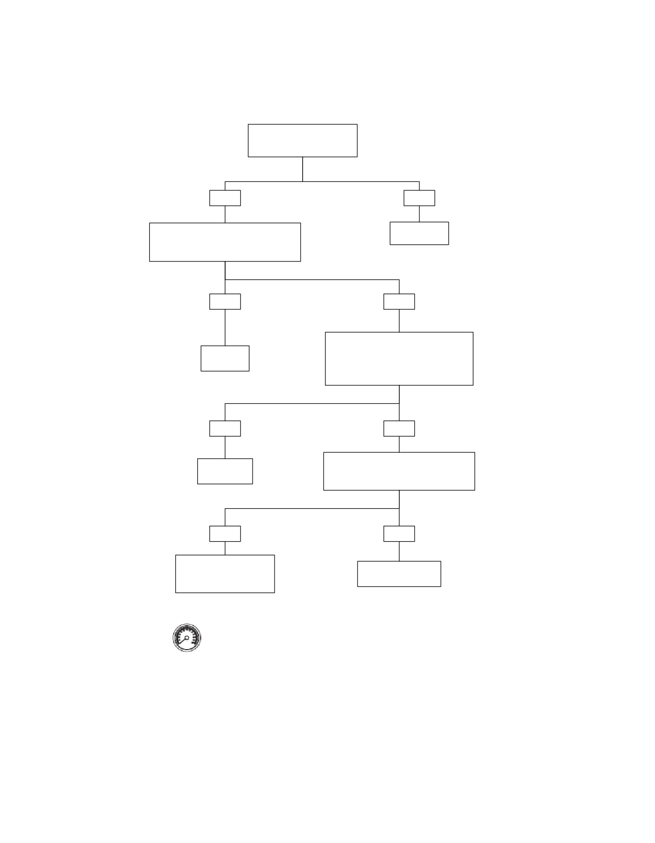
DTC 2107
Clear the DTC. Start the engine.
Open and close the throttle.
Does the DTC reset?
YES
NO
Inspect the ECM connector [78]. Make sure it is
Refer to
fully connected and no poor connections exist
Diagnostic Tips.
on terminal “52” (Y/GN).
Were any poor connections found?
YES
NO
Connect ECM Breakout Box. With the Ignition
Switch on and the Engine Stop Switch in the
Repair poor
RUN position test voltage on terminal “52” to a
connection.
good ground.
Is battery voltage present?
YES
NO
Test for voltage at terminal “87” (Y/GN) wire of
Replace ECM.
the System Relay.
Is voltage present?
YES
NO
Locate and repair open or high
resistance in (Y/GN) wire
Replace System Relay.
between the System Relay and
the ECM.
Clear codes using speedometer self
diagnostics. See 4.6 SPEEDOMETER
SELF DIAGNOSTICS. Confirm proper
fc01331_en
operation with no check engine lamp.
4-192 2008 Touring Diagnostics: Engine Management
HOME
DTC P2119
4.42
GENERAL
DIAGNOSTICS
Refer to Table 4-75. The Throttle Actuation Control (TAC)
Diagnostic Notes
System sets DTC P2119 when the ECM determines that the
Each reference number below correlates to a circled number
throttle plate does not return to the correct de-energized posi-
on the flow chart(s).
tion. This error primarily indicates that there may be non-elec-
trical conditions which affect the throttle body range/perform-
1. The ECM must see this fault during four consecutive igni-
ance.
tion cycles in order to set DTC P2119. When testing to
see if code resets, be sure to operate vehicle through four
Table 4-75. Code Description
complete, consecutive ignition cycles.
2. Replace defective mechanical components in accordance
DTC
DESCRIPTION
with the Service Manual. Follow the flow chart steps
P2119
TAC system throttle body range/perform-
provided, until component replacement directs you to the
ance
Service Manual.
This DTC, if initiated, may have the following probable condi-
tions:
•
Something may be physically interfering with the throttle
plate operation
(i.e. foreign material, debris, physical
obstruction, or loosely/improperly mounted throttle plate).
•
Damaged or broken throttle plate return spring.
•
Defective mechanical component(s) internal to the TCA.
2008 Touring Diagnostics: Engine Management 4-193
HOME
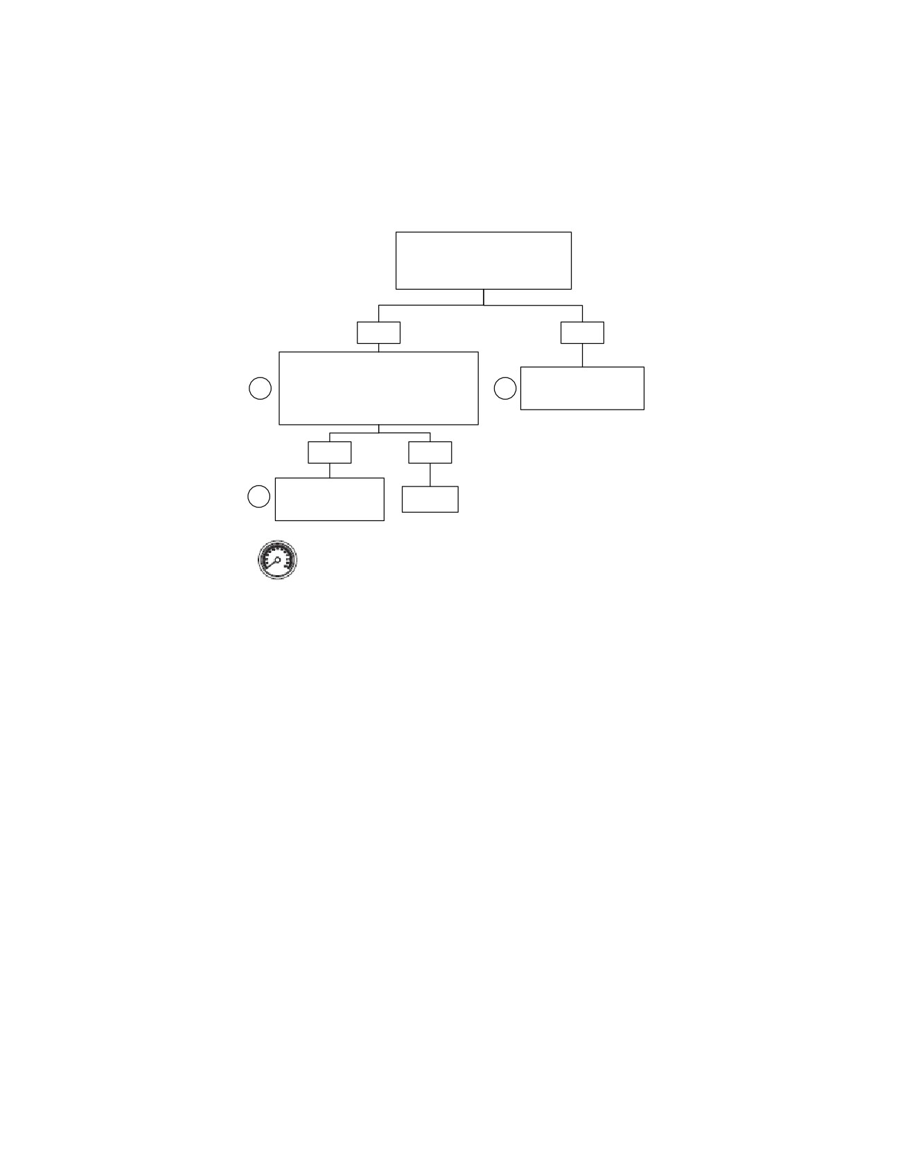
TAC System Throttle Body Range/Performance: DTC P2119
Inspect the air inlet and check for
foreign debris and/or mechanical
interference to the throttle plate.
Was debris or interference found?
YES
NO
Remove obstructions, clean foreign debris
from inlet and check throttle plate for freedom
of movement and full range of motion. Clear
Replace Induction Module.
1
2
the DTC. Start engine and operate throttle.
See Service Manual.
Refer to note.
Does DTC P2119 set?
YES
NO
Replace Induction
2
Repair
Module. See Service
Complete.
Manual.
Clear codes using speedometer self diagnostics. See
4.6 SPEEDOMETER SELF DIAGNOSTICS. Confirm
proper operation with no check engine lamp.
fc01400_en
4-194 2008 Touring Diagnostics: Engine Management

HOME
DTC P2122,
P2123, P2127, P2128
4.43
GENERAL
DIAGNOSTICS
The Twist Grip Sensor (TGS) is an electronic assembly that
PART NUMBER
TOOL NAME
replaces the conventional throttle cable. Two opposing Hall-
HD-41404-B
HARNESS CONNECTOR TEST KIT
effect sensors transmit signals to the ECM. The ECM uses
these signals to determine the desired throttle plate position.
HD-48637
BREAKOUT BOX
The ECM controls the motor in the Throttle Control Actuator
(TCA) to move the throttle plate to the desired position.
Diagnostic Tips
The TGS receive a 5V reference signal from the ECM. As the
•
An intermittent may be caused by poor connection, rubbed
throttle plate is opened the TGS1 signal voltage increases and
through wire insulation or a wire broken inside the insula-
TGS2 signal voltage decreases. By design, the sum of the
tion.
voltages when measured for both TGS1 and TGS2 should
•
Poor connection: Inspect component and harness con-
equal approximately 5.0 volts. If the sum of these voltages is
nectors for backed out terminals, improper mating, broken
not 5.0 volts, then DTCs will be initiated for TGS1 and/or TGS2.
locks, improperly formed or damaged terminals, poor ter-
The ECM monitors and controls the TAC System and generates
minal-to-wire connection and damaged harnesses.
DTCs when errors are reported by the ECM. Refer to
Diagnostic Notes
Table 4-76.
Each reference number below correlates to a circled number
Table 4-76. Code Description
on the flow chart(s).
1. Connect BREAKOUT BOX (Part No. HD-48637) to the
DTC
DESCRIPTION
ECM and ECM harness. See 4.7 BREAKOUT BOX: EFI.
P2122
TGS1 low/open
2. Use HARNESS CONNECTOR TEST KIT (Part No. HD-
P2123
TGS1 high
41404-B), purple pin probes, socket probes and patch
P2127
TGS2 low/open
cords.
P2128
TGS2 high
2008 Touring Diagnostics: Engine Management 4-195
HOME
em00109
Twist Grip Sensor
[224A]
5 67413
5 67413
[224B]
[204A]
6 5 432 1
Electronic
6 5 432 1
[78A]
[78B]
Control Module
[204B]
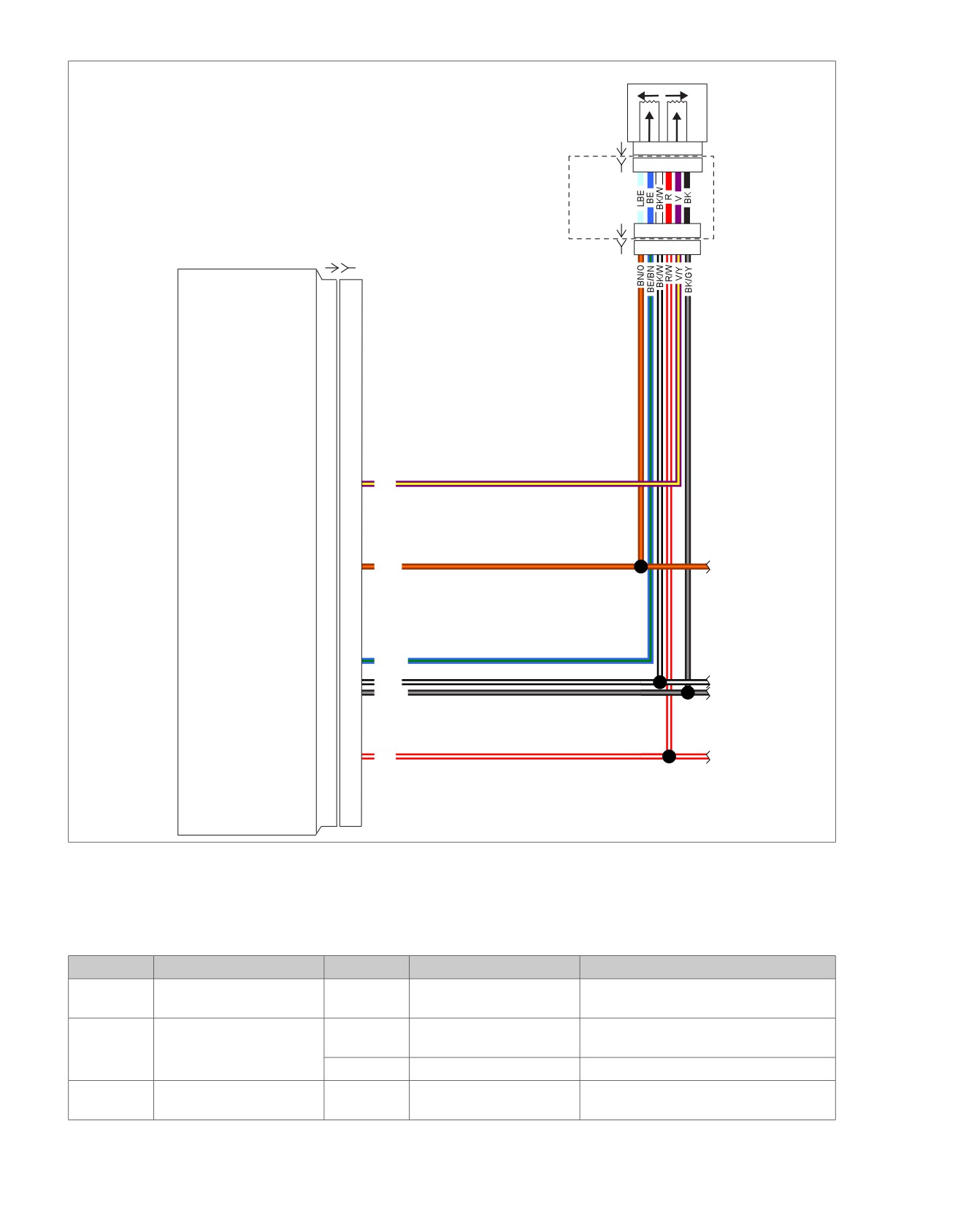
Twist grip sensor-2
39
39
V/Y
To VSS, TCA AND jiffy
5V sensor power-1
50
50
BN/O
stand sensor
Twist grip sensor-1
59
59
BE/GN
5V sensor ground-1
61
61
BK/W
To TCA
5V sensor ground-2
62
62
BK/GY
To TMAP
5V sensor power-2
68
68
R/W
To TMAP
Figure 4-80. Twist Grip Sensor (TGS) Circuit
Table 4-77. Wire Harness Connectors
NO.
DESCRIPTION
MODEL
TYPE
LOCATION
[78]
Electronic Control Module
All
73-place Delphi
Under seat
(ECM)
[204]
Harness connector - Twist
All
except
6-place Molex
Inside fairing front (leading into handlebar
Grip Sensor (TGS)
FLHR
right side)
FLHR
6-place Molex
Inside nacelle
[224]
T
wist Grip Sensor (TGS)
All
7-place Amp (Tyco)
Handlebar throttle (inside right side
handlebar)
4-196 2008 Touring Diagnostics: Engine Management
HOME
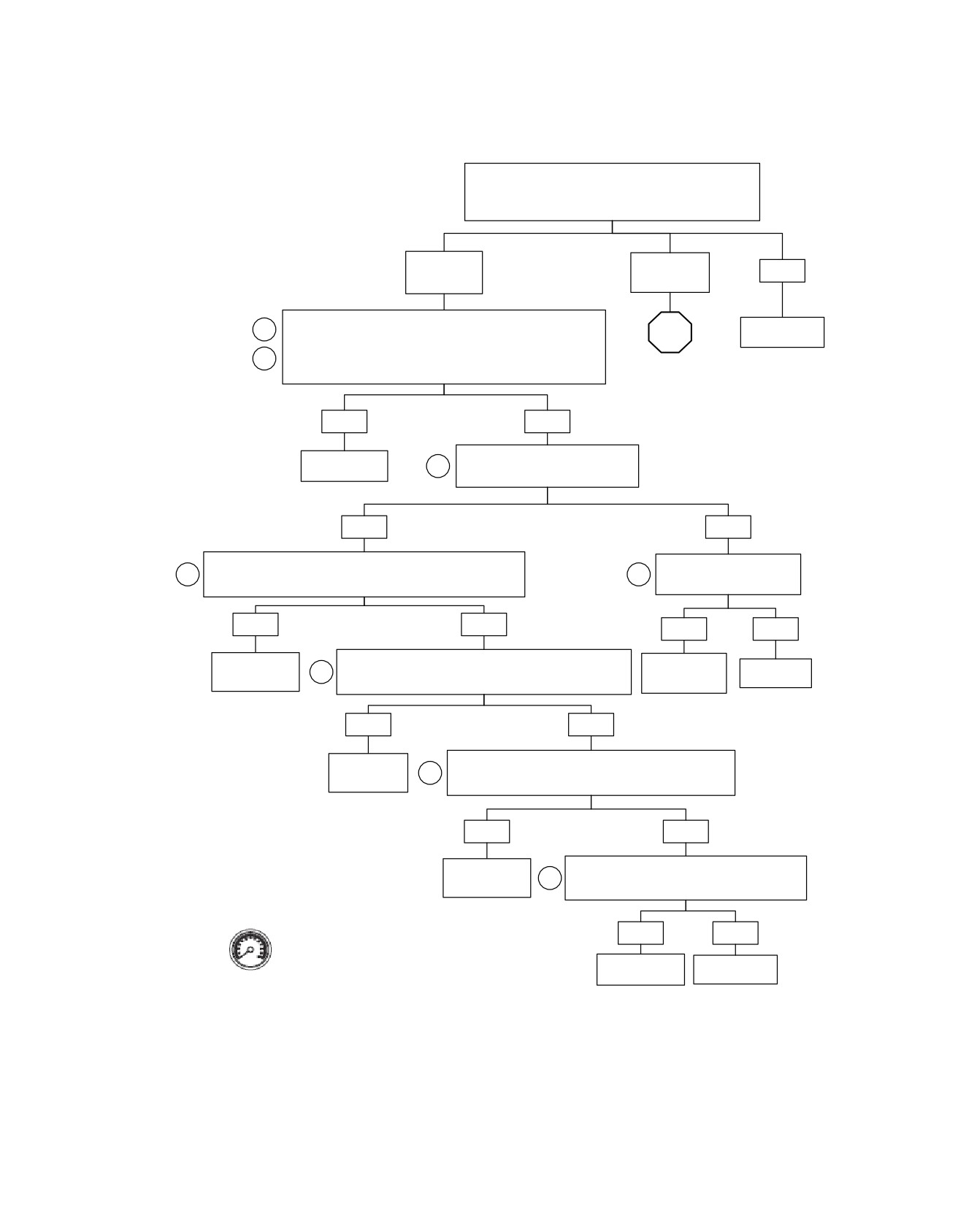
TAC System Throttle Body Range/Performance: DTC P2119 (Part 1 of 2)
Clear the DTC. Start the engine slowly open and close the
throttle. Turn off the engine. Turn the ignition switch on with the
engine stop switch in the RUN position. Check for DTCs.
Did the DTC reset?
YES
YES
DTC P2122 or
DTC P2127 or
NO
P2123
P2128
Install ECM Breakout Box (HD-48637). Turn Ignition Switch on with the
Refer to
1
STOP
Engine Stop Switch in the RUN position. Measure voltage from terminal
Diagnostic Tips.
“59” to terminal “61” of Breakout Box. Twist the throttle completely
2
closed then slowly open the throttle.
Go to TAC System
Does the voltage gradually increase from approximately 0.2V to 4.8V?
Throttle Body Range/
Performance: DTC
P2119 (Part 2 of 2).
YES
NO
Measure voltage from terminal “50” to
Refer to
2
terminal “61” of Breakout Box.
Diagnostic Tips.
Is the voltage approximately 5V?
YES
NO
Disconnect Twist Grip Sensor connector (224). Disconnect ECM from
Test for a short to voltage on
2
Breakout Box. Test for short to voltage on terminal “59” (BE/GN).
2
(BN/O) terminal “50”.
Short to voltage present?
Short to voltage present?
YES
NO
YES
NO
Test for an open or short to ground on (BE/GN) between terminal
Locate and repair
Locate and repair
2
“59” of Breakout Box and terminal 5 of connector (224B).
Replace ECM.
short to voltage.
short to voltage.
Open or short to ground present?
YES
NO
Locate and
Test for an open or short to ground on (BN/O) between terminal
repair open or
2
“50” of Breakout Box and terminal “6” of connector (224).
short to ground..
Open or short to ground present?
YES
NO
Test for an open on (BK/W) between terminal “61” of
Locate and repair
2
Breakout Box and terminal “4” of connector (224).
short to ground.
Open or short to ground present?
YES
NO
Clear codes using speedometer self diagnostics. See
4.6 SPEEDOMETER SELF DIAGNOSTICS. Confirm
proper operation with no check engine lamp.
Locate and repair
Replace Twist
short to ground.
Grip Sensor.
fc01396_en
2008 Touring Diagnostics: Engine Management 4-197
HOME
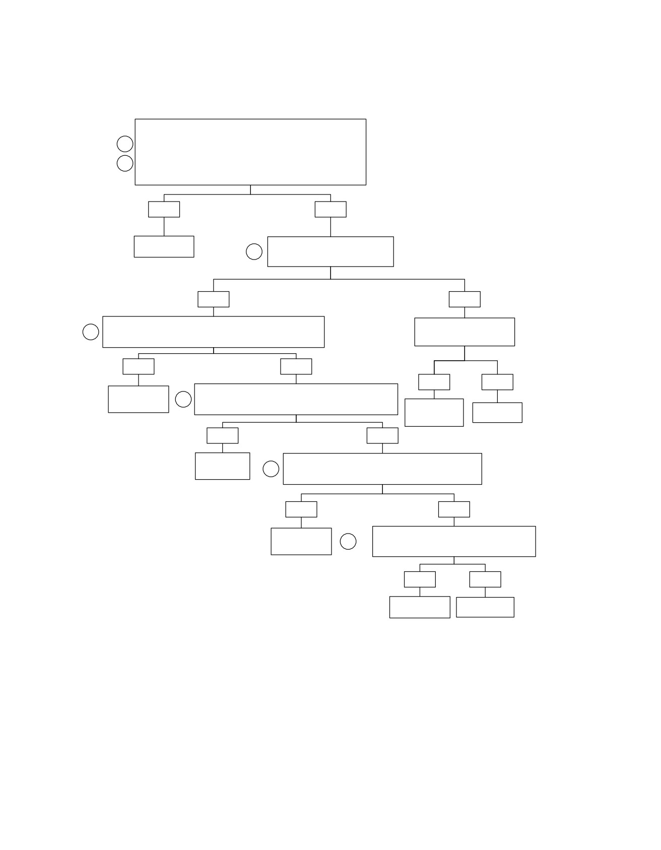
TAC System Throttle Body Range/Performance: DTC P2119 (Part 2 of 2)
Continued from TAC System Throttle Body Range/Performance: DTC
P2119 (Part 1 of 2).
1
Install ECM Breakout Box (HD-48637). Turn Ignition Switch on with the
Engine Stop Switch in the RUN position. Measure voltage from terminal
“39” to terminal “62” of Breakout Box. Twist the throttle completely open
2
then slowly close the throttle al the way to the throttle roll off position.
Does the voltage gradually increase from approximately 0.2V to 4.8V?
YES
NO
Refer to
Measure voltage from terminal “68” to
Diagnostic Tips.
2
terminal “62” of Breakout Box.
Is the voltage approximately 5V?
YES
NO
Disconnect Twist Grip Sensor connector (224). Disconnect ECM from
Test for a short to voltage on
2
Breakout Box. Test for short to voltage on terminal “39” (V/Y).
(R/W) terminal “68”.
Short to voltage present?
Short to voltage present?
YES
NO
YES
NO
Test for an open or short to ground on (V/Y) between terminal
Locate and repair
2
“39” of Breakout Box and terminal 5 of connector (224B).
short to voltage.
Open or short to ground present?
Locate and repair
Replace ECM.
short to voltage.
YES
NO
Locate and
Test for an open or short to ground on (R/W) between terminal
repair open or
2
“68” of Breakout Box and terminal “3” of connector (224).
short to ground.
Open or short to ground present?
YES
NO
Test for an open on (BK/G) between terminal “62” of
Locate and repair
2
Breakout Box and terminal “1” of connector (224).
short to ground.
Open or short to ground present?
YES
NO
Locate and repair
Replace Twist
short to ground.
Grip Sensor.
fc01397_en
4-198 2008 Touring Diagnostics: Engine Management

HOME
DTC P2135,
P2138
4.44
GENERAL
DIAGNOSTICS
The Throttle Actuation Control (TAC) System uses DTC codes
PART NUMBER
TOOL NAME
when the ECM determines that a correlation error exists for
HD-41404-B
HARNESS CONNECTOR TEST KIT
either the Throttle Position (TP) sensor or the Twist Grip Sensor
(TGS).
HD-48637
BREAKOUT BOX
The two TP sensors work opposite of each other. As the throttle
Diagnostic Tips
plate opens, TPS1 voltage ranges from 0.0-5.0V, while TPS2
voltage ranges from 5.0-0.0V. The sum of the two TPS voltages
•
An intermittent may be caused by poor connection, rubbed
should always measure approximately 5.0V.
through wire insulation or a wire broken inside the insula-
tion.
The two TGSs work the same way. As the throttle plate is
opened, TGS1 voltage increases and TGS2 voltage decreases.
•
Poor connection: Inspect component and harness con-
The sum of these two voltages should always measure
nectors for backed out terminals, improper mating, broken
approximately 5.0V. If either of these components fail to cor-
locks, improperly formed or damaged terminals, poor ter-
relate the proper voltage, or has out-of-range voltage condi-
minal-to-wire connection and damaged harnesses.
tions, then the ECM will initiate a DTC. Refer to Table 4-78.
Diagnostic Notes
Table 4-78. Code Description
Each reference number below correlates to a circled number
on the flow chart(s).
DTC
DESCRIPTION
1. Connect BREAKOUT BOX (Part No. HD-48637) to the
P2135
TPS correlation error
ECM and ECM harness. See 4.7 BREAKOUT BOX: EFI.
P2138
TGS correlation error
2. Use HARNESS CONNECTOR TEST KIT (Part No. HD-
41404-B), purple pin probes, socket probes and patch
cords.
3. Replace defective mechanical components in accordance
with the Service Manual. Follow the flow chart steps
provided until component replacement directs you to the
Service Manual.
2008 Touring Diagnostics: Engine Management 4-199
HOME
em00110
Twist Grip Sensor
Throttle
Control Actuator
[224A]
5 6 74 1 3
5 6 74 1 3
[224B]
[211A]
6
5
4
3
2
1
6
5
4
3
2
1
[204A]
[211B]
6 54 321
Electronic
6 54 321
[78A]
[78B]
Control Module
[204B]
Throttle by wires HI
29
29
BK/O
Throttle by wires LO
30
30
BK/PK
Throttle pos. Sensor-2
36
36
BN/R
Throttle pos. Sensor-1
37
37
BN/V
Twist grip sensor-2
39
39
V/Y
5v sensor power-1
50
50
BN/O
Twist grip sensor-1
59
59
BE/GN
5V sensor ground-1
61
61
BK/W
5V sensor ground-2
62
62
BK/GY
5V sensor power-2
68
68
R/W
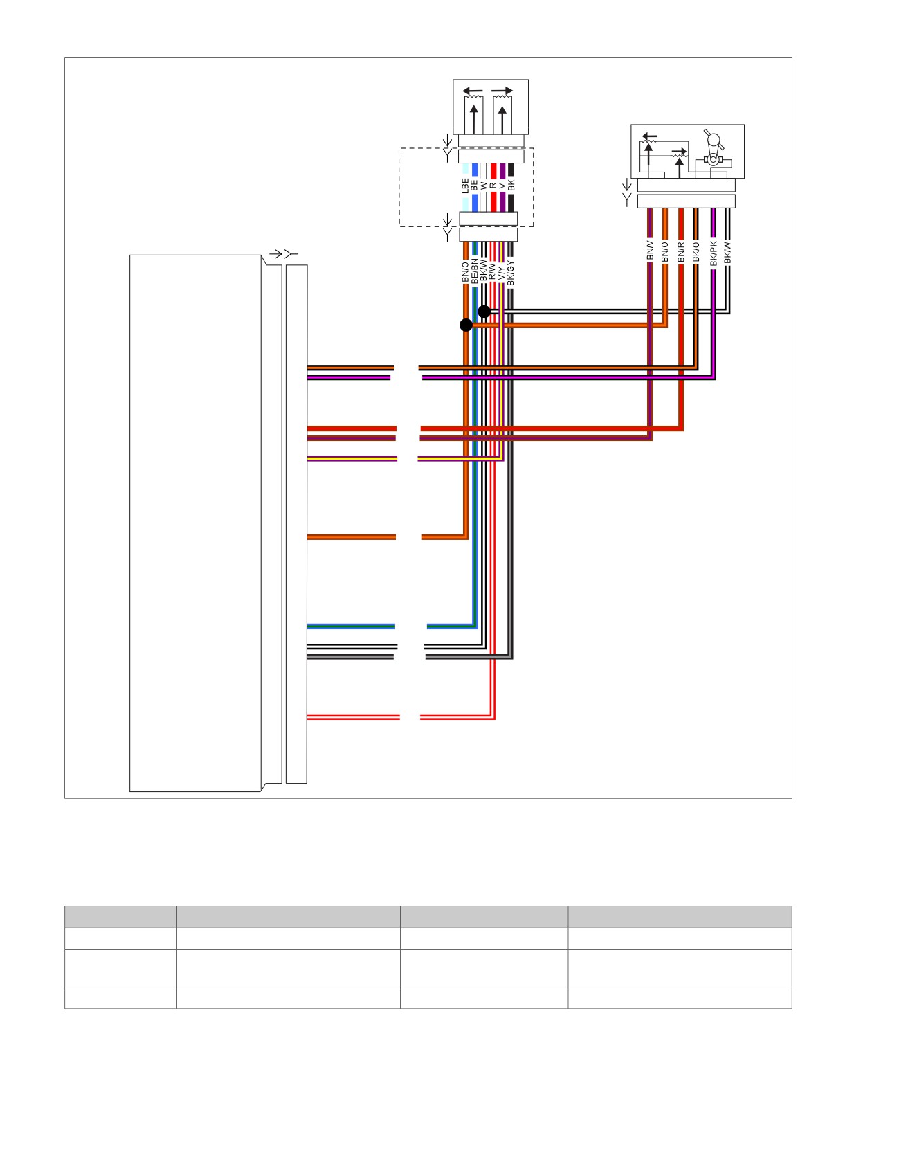
Figure 4-81. TGS/TPS Control Circuit
Table 4-79. Wire Harness Connectors
NO.
DESCRIPTION
TYPE
LOCATION
[78]
Electronic Control Module (ECM)
73-place Delphi
Under seat
[204]
T
wist Grip Sensor (TGS)
6-place Molex
Right hand control (inside right
handlebar)
[211]
Throttle Control Actuator (TCA)
6-place Molex
Air inlet manifold (right side)
4-200 2008 Touring Diagnostics: Engine Management
HOME
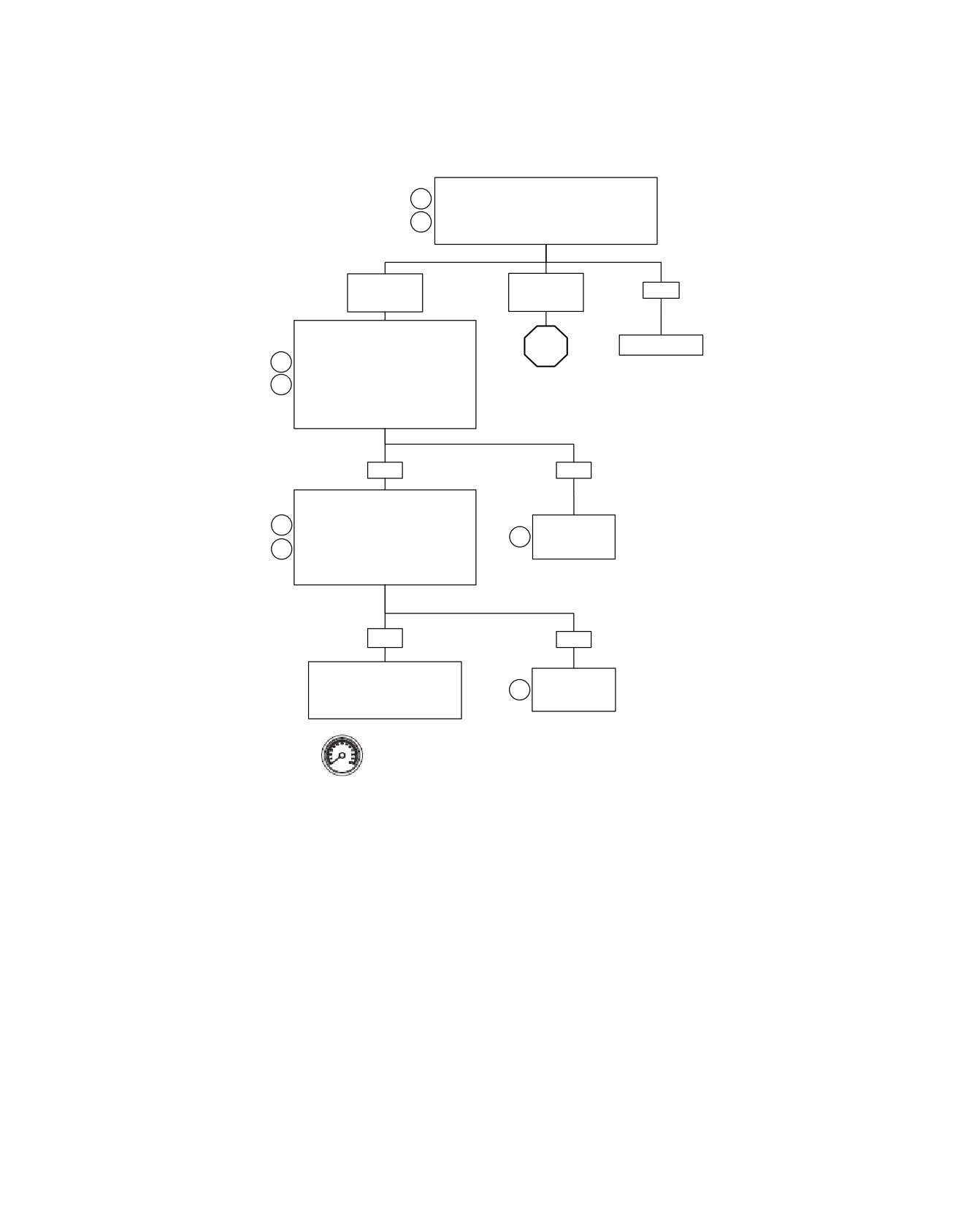
Throttle Actuation Control: DTC P2135, P2138 (Part 1 of 2)
Connect Breakout Box to ECM connector [78].
1
Start vehicle and clear existing DTCs.
Then recheck codes.
2
Was DTC P2135 or P2138 displayed?
YES
YES
NO
DTC P2135
DTC P2138
Using a DVOM, measure TPS1 voltage
on Breakout Box terminals “37” and
STOP
No System Fault.
“61”, while gradually opening throttle.
1
Does voltage increase steadily with no
Go to Throttle
2
spikes for low voltages from 0.2 to 1.0
Actuation Control:
volt at idle (closed throttle) to 4.2 to 4.8
DTC P2135, P2138
volts at wide open throttle?
(Part 2 of 2).
YES
NO
Using a DVOM, measure TPS2 voltage
on Breakout Box terminals “36” and
1
“61”, while gradually opening throttle.
Replace TCA.
Does voltage increase steadily with no
3
See Touring
2
spikes for low voltages from 0.2 to 1.0
Service Manual.
volt at wide open throttle, to 4.2 to 4.8
volts at idle (closed throttle)?
YES
NO
See 4.20 DTC P0120, P0122,
Replace TCA.
P0123, P0220, P0222, P0223
3
See Touring
and investigate faults in the
Service Manual.
electrical circuit of the TCA.
Clear codes using speedometer self diagnostics. See 4.6
SPEEDOMETER SELF DIAGNOSTICS. Confirm proper
operation with no check engine lamp.
fc01436_en
2008 Touring Diagnostics: Engine Management 4-201
HOME
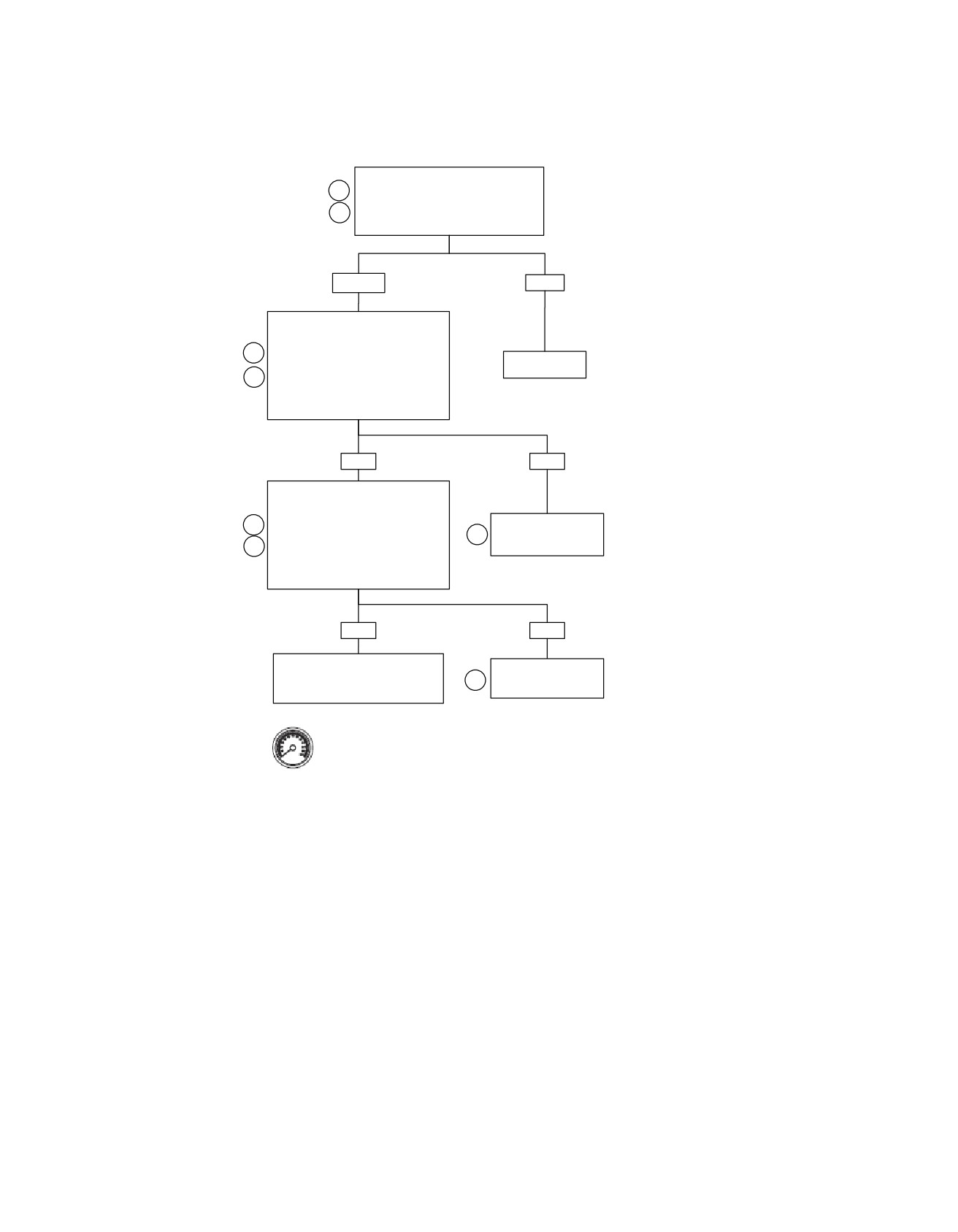
Throttle Actuation Control: DTC P2135, P2138 (Part 2 of 2)
Continued from Throttle Actuation
1
Control: DTC P2135, P2138
(Part 1 of 2).
2
Was DTC P2138 displayed?
YES
NO
Using a DVOM, measure TGS1 voltage
on Breakout Box terminals “59” and
“61”, while gradually opening throttle.
1
No system fault.
Does voltage increase steadily with no
2
spikes for low voltages from 0.2 to 1.0
volt at idle (closed throttle) to 4.2 to 4.8
volts at wide open throttle?
YES
NO
Using a DVOM, measure TGS2 voltage
on Breakout Box terminals “39” and
“61”, while gradually opening throttle.
1
Replace TGS. See
3
Touring Service
Does voltage increase steadily with no
2
Manual.
spikes for low voltages from 0.2 to 1.0
volt at wide open throttle, to 4.2 to 4.8
volts at idle (closed throttle)?
YES
NO
See 4.43 DTC P2122, P2123,
Replace TGS. See
P2127, P2128 and investigate faults
3
Touring Service
in the electrical circuit of the TGS.
Manual.
Clear codes using speedometer self diagnostics. See
4.6 SPEEDOMETER SELF DIAGNOSTICS. Confirm
fc01437_en
proper operation with no check engine lamp.
4-202 2008 Touring Diagnostics: Engine Management
HOME
DTC P2176
4.45
If the ECM is not able to learn the minimum position, or if the
GENERAL
learning fails four consecutive ignition cycles, the ECM will
The Throttle Actuation Control (TAC) System sets DTC P2176
initiate a DTC P2176. Refer to Table 4-80.
when the ECM determines that the zero position of the throttle
plate has not been successfully learned.
Table 4-80. Code Description
At power up, the ECM adjusts the throttle plate to the "limp-
DTC
DESCRIPTION
home" position, then begins to move the throttle plate closed.
The ECM monitors and verifies the amount of movement that
P2176
TAC close position not learned
occurred. The throttle plate minimum position is held briefly
then verified against the expected minimum and maximum
DIAGNOSTICS
range of throttle. If the zero position is found within range, then
Refer to and conduct diagnostics as identified on the flow chart.
the position is stored.
2008 Touring Diagnostics: Engine Management 4-203
HOME
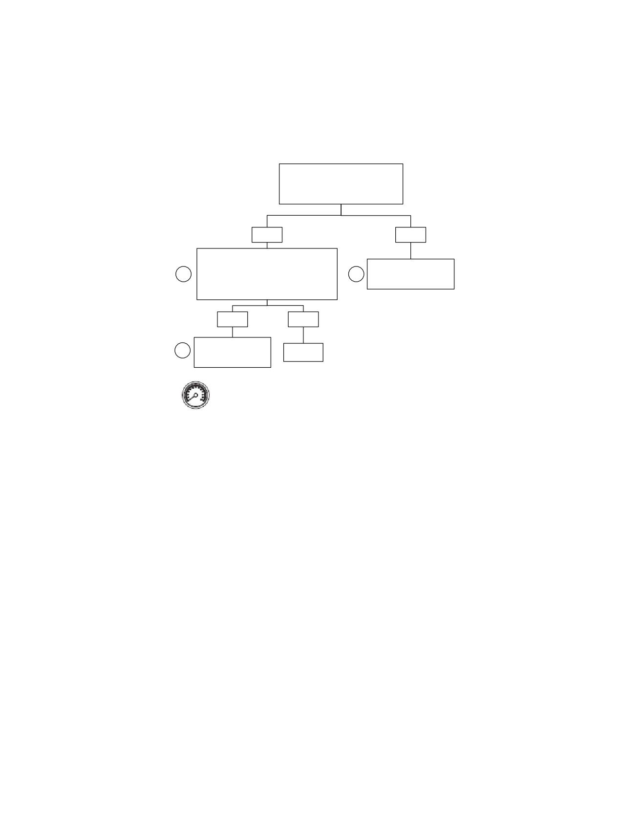
TAC Closed Position Not Learned: DTC P2176
Inspect the air inlet and check for
foreign debris and/or mechanical
interference to the throttle plate.
Was debris or interference found?
YES
NO
Remove obstructions, clean foreign debris
from inlet and check throttle plate for freedom
of movement and full range of motion. Clear
Replace Induction Module.
1
2
the DTC. Start engine and operate throttle.
See Service Manual.
Refer to note.
Does DTC P2176 set?
YES
NO
Replace Induction
2
Repair
Module. See Service
Complete.
Manual.
Clear codes using speedometer self diagnostics. See
4.6 SPEEDOMETER SELF DIAGNOSTICS. Confirm
proper operation with no check engine lamp.
fc01398_en
4-204 2008 Touring Diagnostics: Engine Management
HOME
DTC U1064
4.46
GENERAL
ed02043
Loss of TSM/TSSM/HFSM Serial Data
1
The serial data connector provides a means for the Electronic
Control Module (ECM), TSM/TSSM/HFSM and speedometer
to communicate their current status. When all operating para-
meters on the serial data link are within specifications, a state
of health message is sent between the components. A Dia-
gnostic Trouble Code
(DTC) U1064 indicates that the
TSM/TSSM/HFSM is not receiving this state of health message.
A DTC U1064 also indicates that there was communication on
the data bus since power up, but communication was lost or
interrupted during that key cycle.
Table 4-81. Code Description
DTC
DESCRIPTION
U1064
Loss of TSM/TSSM/HFSM serial data
U1255
Serial data error/missing message
DIAGNOSTICS
3
2
PART NUMBER
TOOL NAME
1.
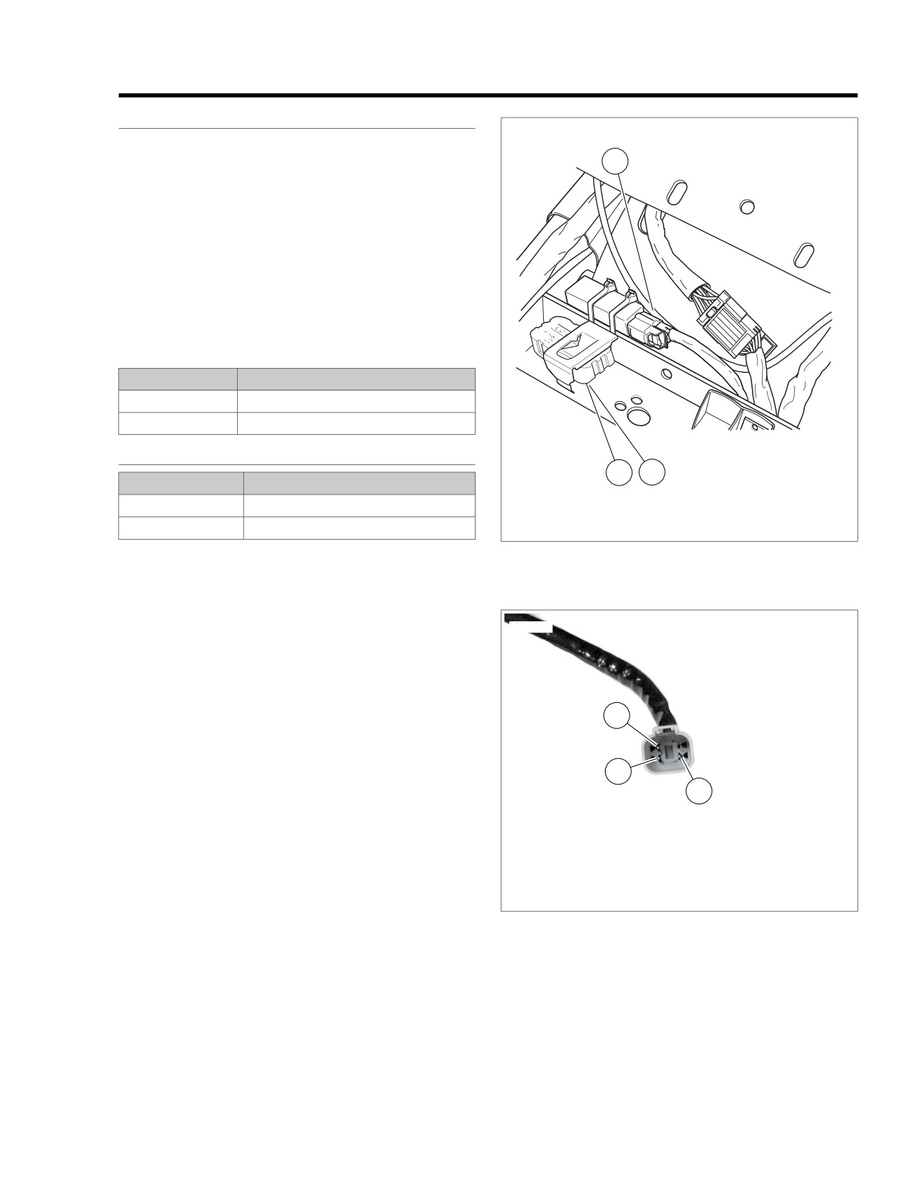
[30] TSM/TSSM/HFSM
HD-42682
BREAKOUT BOX
2.
[208] HFSM antenna jumper harness
HD-48637
BREAKOUT BOX
3.
[209] HFSM antenna
Diagnostic Notes
Figure 4-82. TSM/TSSM/HFSM Location
Each reference number below correlates to a circled number
on the flow chart(s).
1. Connect BREAKOUT BOX (Part No. HD-42682) as fol-
ed02982
lows:
a. Mate gray socket housing on Breakout Box with
TSM/TSSM/HFSM connector [30A].
b. Mate gray pin housing on Breakout Box with harness
connector [30B].
3
2. Connect BREAKOUT BOX (Part No. HD-48637).
2
1
1. Terminal 2: ground (BK/GN)
2. Terminal 3: serial data (LGN/V)
3. Terminal 4: power (GY)
Figure 4-83. Data Link Connector
2008 Touring Diagnostics: Engine Management 4-205