Harley Davidson 2018 softail models. Service manual - page 28
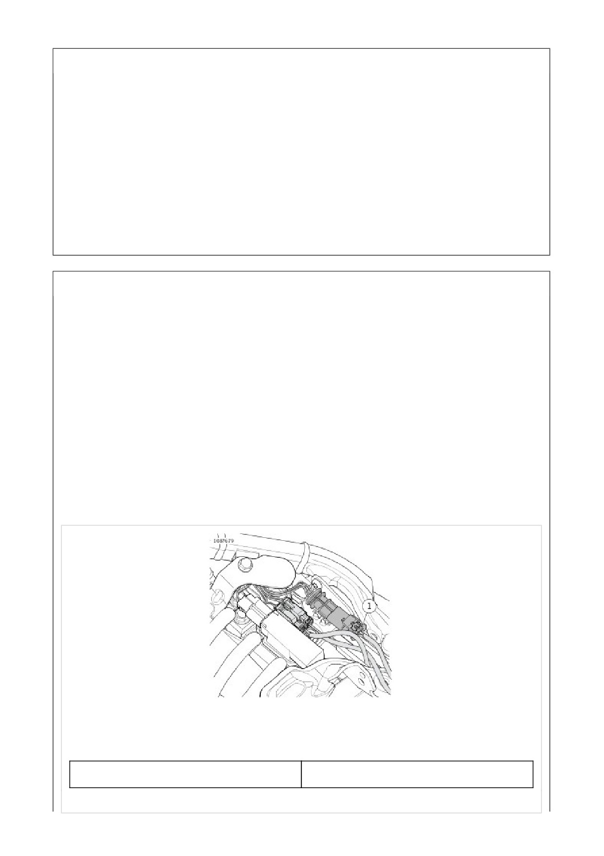
Remove
1. See Figure 1. Disconnect license plate connector (1).
2. Disconnect pins from connector (1). See electrical
diagnostic manual.
3. See Figure 2. Discard cable straps (1).
4. Remove screws (2).
5. Remove license plate holder (3).
6. Remove wire bundle (4) from frame.
7. See Figure 3. Remove screws (1) and washers (2).
8. Remove LED housing (3).
Install
1. See Figure 3. Install LED housing (3).
2. Install screws (1) and washers (2). Tighten.
Torque: 1.1-2.3 N·m (10-20 in-lbs) License plate, LED
housing, screw
3. See Figure 2. Route wire bundle (4) through frame.
4. Install license plate holder (3).
5. Install screws (2). Tighten.
Torque: 9.5-15 N·m (84-133 in-lbs) License plate
holder, screw
6. Route harness and install new cable straps (1).
7. Connect pins to connector (1). See electrical diagnostic
manual.
8. See Figure 1. Connect license plate connector (1).
1
License plate light connector
Figure 1. License Plate Light Connector
1
Cable strap (2)
2
Screw (4)
3
License plate holder
4
Wire bundle
Figure 2. License Plate Holder
1
Screw (2)
2
Washer (2)
3
LED Housing
Figure 3. License Plate Mount LED Housing
Remove
1. See Figure 1. Disconnect connectors.
a. License Plate: Disconnect connector (2).
b. Left Signal: Disconnect connectors (1).
2. See Figure 2. Remove left fender support.
a. Remove screws (2).
b. Remove screws (4) and washers (3).
c. Remove fender support (1).
3. See Figure 3. Remove harness.
a. Discard wire retention pads (1).
b. Remove harness (2).
4. See Figure 1. Disconnect pins from connector (2). See
electrical diagnostic manual.
5. See Figure 4. Disassemble turn signal.
a. Remove screw (1) and washer (2).
b. Disassemble license plate mounting support and
turn signal.
c. Remove screws (4) and cover (5).
d. Remove lamp (3) with harness.
Install
1. See Figure 4. Assemble turn signal.
a. Install lamp (3).
b. Install cover (5) and screws (4). Tighten.
Torque: 0.9-1.8 N·m (8-16 in-lbs) License Plate
Lamp Cover, Screw
c. Route harness, assemble license plate mounting
support and turn signal. See Bulb Replacement.
d. Install screw (1) and washer (2).
Torque: 20-24 N·m (15-18 ft-lbs) Rear Turn Signal,
Fender Mount, Screw
2. See Figure 1. Connect pins to connector (2). See
electrical diagnostic manual.
3. See Figure 3. Install harness.
a. Route harness (2) through fender support (4).
b. Install new wire retention pads (1).
4. See Figure 2. Install fender support.
a. Install fender support (1), washers (3) and screws
(4). Tighten.
Torque: 57-62.3 N·m (42-46 ft-lbs) Fender Support,
Screw
b. Install screws (2). Tighten.
Torque: 28-37 N·m (21-27 ft-lbs) Fender Support,
Screw
5. See Figure 1. Connect connectors.
a. License Plate: Disconnect connector (2).
b. Left Signal: Disconnect connectors (1).
1
Left lamp connector
2
License plate light connector
Figure 1. License Plate Lamp Connector
1
Fender support
2
Screw, long or short (2)
3
Washer (2)
4
Screw (2)
Figure 2. Right Fender Support
1
Wire retention pads (3)
2
Harness, license plate
3
Harness, left signal
4
Fender support
Figure 3. Left Fender Support
1
Screw
2
Washer
3
License plate lamp
4
Screw (2)
5
Cover
Figure 4. Turn Signal Assembly
1. Install seat. See Remove.
2. Install main fuse. See Main Fuse.
1. Remove left side cover. See Remove.
2. Remove main fuse. See Main Fuse.
1. See CAN Terminating Resistor. Remove terminating
resistor.
1. See Figure 1. Install terminating resistor.
Figure 1. CAN Terminating Resistor
1. Install main fuse. See Main Fuse.
2. Install left side cover. See Remove.

Special Tools
Description
Part Number
Qty.
DIGITAL TECHNICIAN II
HD-48650
1
NOTE
Always calibrate replaced ECM (Electronic control module) with DIGITAL TECHNICIAN II (Part Number:HD-48650).
1. Remove seat. See Remove.
2. Remove main fuse. See Main Fuse.
1. Release and move sub caddy mounting bracket.
a. See Figure 1. Remove screw (3).
b. Disconnect front sub caddy lock (1).
c. Disconnect rear sub caddy lock (2).
d. Route sub caddy out-of-way.
1
Front sub caddy lock
2
Rear sub caddy lock
3
Sub caddy screw
Figure 1. ECM Sub Caddy
2. Remove ECM (Electronic control module).
a. See Figure 2. Slide ECM forward.
b. Remove ECM from caddy.
c. Disconnect ECM connectors.
d. Remove ECM.
Figure 2. ECM Removed
1. Install ECM (Electronic control module).
a. See ECM Removed. Connect ECM connectors.
Verify locking tabs are in the lock position.
b. Install ECM into caddy.
2. Install sub caddy mounting bracket.
a. See ECM Sub Caddy. Route sub caddy into position.
b. Push and lock into position the rear sub caddy lock
(2).
c. Push and lock into position the front sub caddy lock
(1).
d. Install screw (3). Tighten
Torque: 4.1-6.8 N·m (36-60 in-lbs) Sub caddy screw
1. Install seat. See Remove.
2. Install main fuse. See Main Fuse.

Special Tools
Description
Part Number
Qty.
DIGITAL TECHNICIAN II
HD-48650
1
NOTE
Always calibrate replaced BCM (Body control module) with DIGITAL TECHNICIAN II (Part Number:HD-48650).
1. Remove seat. See Remove.
2. Disconnect negative battery cable. See Main Fuse.
3. Remove battery tray. See Prepare.
1. Remove BCM (Body control module).
a. See Figure 1. Disconnect BCM [242] (1).
b. See Figure 2. Move BCM out of caddy.
NOTE
If rotating the BCM to access components behind
BCM, do not disconnect BCM battery power or
remove BCM.
c. Disconnect BCM battery power [259] (1).
d. Remove BCM (2).
1
BCM [242]
2
BCM
3
Caddy
Figure 1. BCM [242]

1
BCM battery power [259]
2
BCM
3
Caddy
Figure 2. BCM [259]
1.
NOTE
When installing battery power connector verify seal
does not roll.
Install BCM (Body control module).
a. See BCM [259]. Connect BCM battery power
[259](1).
b. See BCM [242]. Install BCM (2) into caddy (3).
c. Connect BCM [242] (1).
1. Install battery tray. See Prepare.
2. Connect negative battery cable. See Main Fuse.
3. Install seat. See Remove.
Activation consists of assigning two fobs to the system and entering an initial PIN.
NOTE
If the fob is lost or inoperable, the PIN allows the owner to disarm the system. See General.
1. Configure the security system by assigning both fobs to the vehicle.
2. Configure the security system by entering a PIN picked by the owner.
Record the PIN in the owner's manual. Instruct the customer to carry a copy (use the wallet card found in the owner's
manual). See General.
Once the system has been activated, it "arms" within 5 seconds of switching the IGN switch to OFF and no motorcycle
motion.
Special Tools
Description
Part Number
Qty.
DIGITAL TECHNICIAN II
HD-48650
1
Use DIGITAL TECHNICIAN II (Part Number:HD-48650) to assign both fobs to the vehicle.
NOTE
Choose the correct fob type. Choosing incorrectly at the beginning of the process will result in a failure to assign
the fob. This can be mistakenly diagnosed as a bad fob or SCM.
When assigning a fob, keep the fob within 1 m (3 ft) of the vehicle seat.
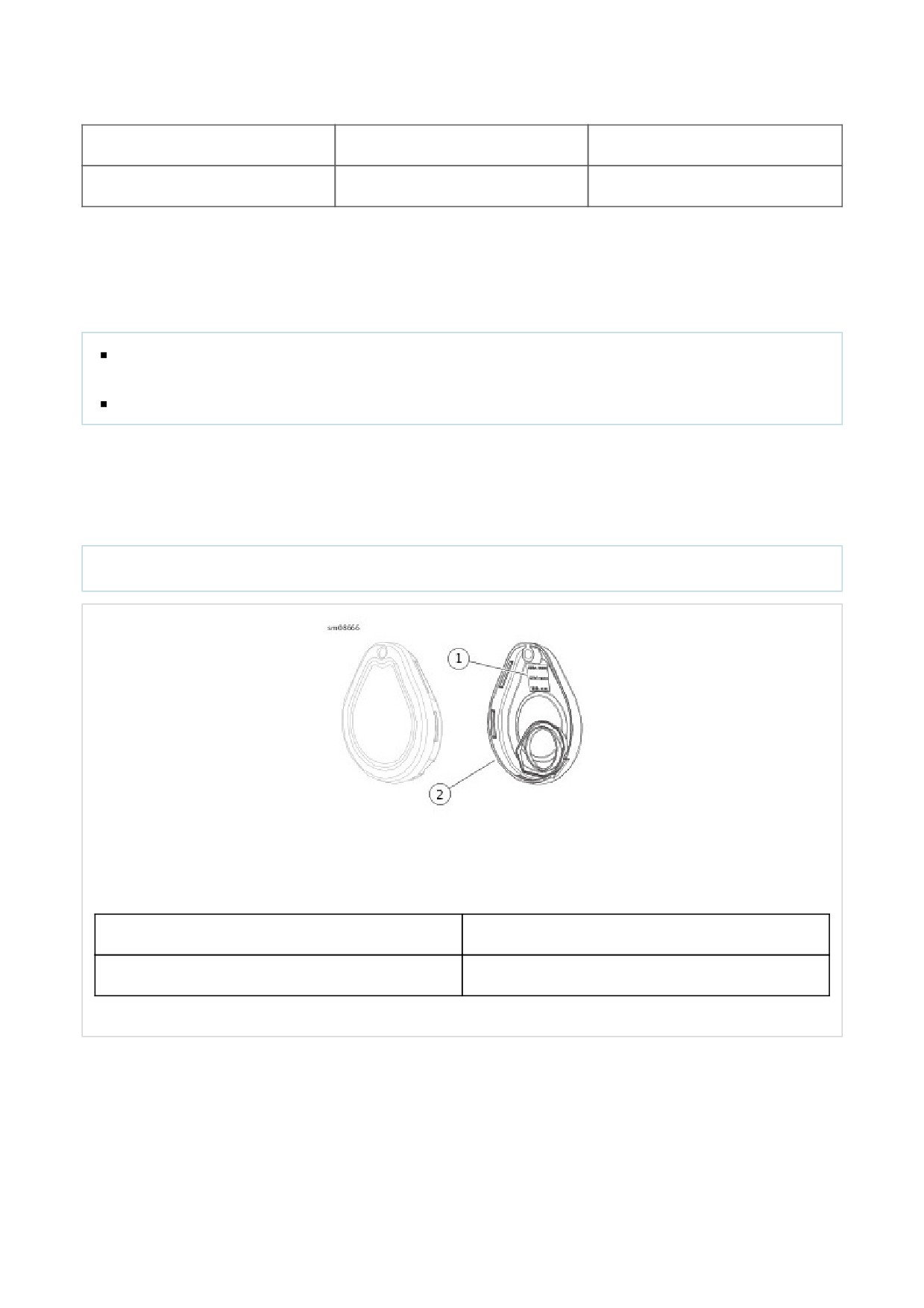
See Figure 1. Follow the menu prompts to scan the fob serial number with the bar code reader. Alternatively, enter the
number using the keyboard. Use DIGITAL TECHNICIAN II (Part Number:HD-48650) to assign fob and enter initial PIN.
NOTE
Each fob has a unique serial number. Attach fob label to a blank NOTES page in the owner's manual for reference.
1
Fob serial number
2
Fob cover
Figure 1. Fob Serial Number
The PIN consists of five digits. Each digit can be any number from 1 through 9. There can be no zeros (0) in the PIN. Use
the PIN to disarm the security system in case the fob becomes unavailable.

The rider can change the PIN at any time. Refer to Table 1.
Modifying an Existing PIN
If a PIN was previously entered, the odometer will display the equivalent digit. Each additional press of the left turn
switch will increment the digit.
Examples:
To advance from 5 to 6, press and release the left turn switch 1 time.
To advance from 8 to 2, press and release the left turn switch 3 times (9-1-2).
Table 1. Changing the PIN
STEP
ACTION
WAIT FOR CONFIRMATION
NOTES
NO.
1
Select a 5-digit (1 thru 9) PIN and record
on the wallet card from owner's manual.
2
With an assigned fob present, turn the
engine stop switch to OFF.
3
Turn the OFF/RUN switch to RUN.
4
Cycle the OFF/RUN switch twice: RUN -
OFF - RUN - OFF - RUN.
5
Press left turn signal switch two times.
ENTER PIN will scroll through the
odometer window.
6
Press right turn signal switch one time
Turn signals will flash three times.
and release.
Current PIN will appear in
odometer. The first digit will be
flashing.
7
Enter first digit of new PIN by pressing
and releasing the left turn signal switch
until the selected digit appears.
8
Press right turn signal switch one time
The new digit will replace the
and release.
current in odometer window.
9
Enter second digit of selected PIN by
pressing and releasing the left turn
signal switch until the selected digit is
present.
10
Press right turn signal switch one time
The new digit will replace the
and release.
current in odometer window.
11
Enter third digit of the selected PIN by
pressing and releasing the left turn
signal switch until the selected digit is
present.

12
Press right turn switch one time and
The new digit will replace the
release.
current in odometer window.
13
Enter fourth digit of new PIN by pressing
and releasing the left turn signal switch
until the selected digit is present.
14
Press right turn switch one time and
The new digit will replace the
release.
current in odometer window.
15
Enter fifth digit of the new PIN by
pressing and releasing the left turn
signal switch until the selected digit is
present.
16
Press right turn switch one time and
The new digit will replace the
release.
current in odometer window.
17
Turn the engine stop switch OFF, then
Pushing the engine stop
turn the ignition switch to OFF.
switch to OFF stores
the new PIN in the
module.
Special Tools
Description
Part Number
Qty.
DIGITAL TECHNICIAN II
HD-48650
1
With a fob present, the security system can be configured for service by disabling the security system with DIGITAL
TECHNICIAN II (Part Number:HD-48650).
Once disabled, the vehicle can be operated without an assigned fob present. To maintain the service mode, the assigned
fobs must be kept out of range. If the fob appears in range, the service mode is cancelled.

It is possible to arm the security system without enabling the motion detector for one ignition cycle. The motorcycle can be
moved in an armed state. The motorcycle cannot be turned on or started while in transport mode until the fob is present.
To Enter Transport Mode
1. With security fob present, set the OFF/RUN switch to RUN.
2. Set the OFF/RUN switch to OFF.
3. Simultaneously press both the left and the right turn signal switches within five seconds of turning the
OFF/RUN switch to OFF.
4. Following a single flash, the turn signals flash three times to indicate that the system is armed in transport
mode.
To Exit Transport Mode
With the fob present, set the OFF/RUN switch to RUN to disarm the system and exit transport mode.
Battery Replacement Schedule
Replace the fob battery every year.
Battery Replacement
1. Open the fob case.
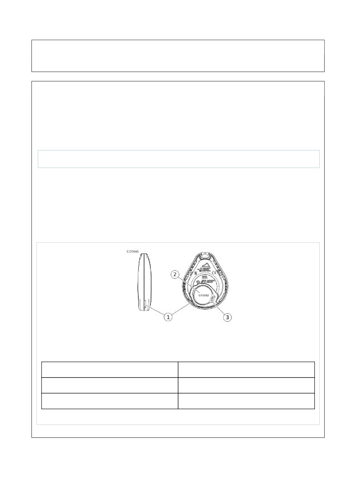
a. See Figure 1. Place a thin blade in the thumbnail slot (1).
b. Twist the blade to separate cases.
NOTE
Use a CR2032 or equivalent battery.
2. Install a new battery with the positive side up.
a. Push the latch (3) away from the battery.
b. Lift the battery from the side opposite the latch.
c. Verify that the metal tabs will firmly contact battery. Bend up slightly if necessary.
d. Install the battery against the latch with the positive side up. Drop into place.
3. Close the case.
a. Align case halves.
b. Snap case halves together.
1
Thumbnail slot
2
Battery (CR2032)
3
Latch
Figure 1. Replace Fob Battery
Battery Replacement Schedule
The siren internal 9 V battery is rechargeable and does not require regular replacement. Battery life under normal
conditions is approximately 3-6 years.
NOTE
If the motorcycle battery is less than 12.5 V, the internal siren battery may not charge.
Battery Replacement
1. Disarm system. Remove siren.
2. See Figure 1. With a small screwdriver, push the catches (1) in through the two slots (2) in the end of the siren.
Release the battery cover (3).
NOTE
For protection against corrosion, battery terminals and battery clip are covered with a special grease. Do not
wipe away this substance. Apply all available existing grease to terminals on new battery.
Use only a 9 V nickel metal hydride battery in the siren.
3. Replace 9 volt battery (4) by removing old battery from polarized battery clip.
4. Recharge and install or install a new 9 volt nickel metal hydride battery.
5. Install cover (3).
a. Carefully replace the rubber seal (5) on the cover.
b. Align battery cover with case placing round corners on cover away from connector [142A] (6).
c. Snap cover into place.
6. Install siren and check operation. Two chirps after an arming command indicate a working siren.
1
Catch (2)
2
Slot (2)
3
Cover

4
9V battery
5
Rubber seal
6
Connector [142A]
Figure 1. Battery Compartment
1. Remove right side cover. See Remove.
2. Disconnect negative battery cable. See Main Fuse.
3. Remove battery. See Prepare.
4. Remove battery tray. See Prepare.
5. Rotate BCM (Body control module) out-of-way. See
Prepare.
1. See Security Siren and BCM Caddy: (Removed for
clarity). Remove security siren (3).
2. Disconnect connector (4).
1. First-time security siren is being installed: Disconnect
security siren connector (5) from back side of BCM (Body
control module) caddy (2).
2. See Figure 1. Connect connector (4).
3. Install security siren into front side of BCM caddy (7).
a. Verify that sounder disc (1) is facing to the rear of the
vehicle.
b. Place security siren into BCM caddy and press into
place locking retainer tabs (6).
1
Sounder disc
2
Back side, BCM caddy
3
Security siren
4
Siren connector
5
Siren connector storage port
6
Retainer tab
7
Front side, BCM caddy
Figure 1. Security Siren and BCM Caddy: (Removed for clarity)
1. Install BCM (Body control module). See Prepare.
2. Install battery tray. See Prepare.
3. Install battery. See Prepare.
4. Connect negative battery cable. See Main Fuse.
5. Install right side cover. See Remove.
1. Remove main fuse. See Main Fuse.
2. Remove seat. See Remove.
1. See Security Antenna. Remove antenna (1).
a.
Remove antenna from caddy.
b.
Disconnect connector (2).
c.
Remove antenna.
1. See Figure 1. Install antenna (1).
a.
Connect connector (2).
b.
Connect antenna to caddy.
1
Antenna
2
Connector
Figure 1. Security Antenna
1. Install seat. See Remove.
2. Install main fuse. See Main Fuse.
1. Remove main fuse. See Main Fuse.
2. Remove voltage regulator. See Prepare.
1. Crankshaft Position (CKP) Sensor Disconnect
connector.
a. Disconnect connector (1).
b. Detach connector (1) from voltage regulator bracket.
2. Remove sensor.
a.
Remove screw (2).
b.
Remove sensor (3).
3. CKP Sensor Assembly Discard O-ring.
1. See Figure 2. Install new O-ring.
a. Lubricate new O-ring with clean engine oil.
b. Install new O-ring.
2. See Figure 1. Install sensor.
a. Install sensor (3).
b. Install screw (2). Tighten.
Torque: 10.2-13.6 N·m (90-120 in-lbs) Sensor, CKP,
screw
3. Connect connector.
a. Attach connector (1) to voltage regulator bracket.
b. Connect connector (1).
1
Connector
2
Screw
3
Sensor
Figure 1. Crankshaft Position (CKP) Sensor
Figure 2. CKP Sensor Assembly