Harley Davidson 2018 softail models. Service manual - page 13
Disassemble
1.
See Figure 1. Remove saddlebag lid.
a. Open saddlebag lid (4).
b. Remove screws (7) and tether bracket (14).
c. Remove screws (8) and medallion (15).
d. Remove saddlebag lid.
2.
Remove reflector.
a. Remove retainer clips (11).
b. Remove reflector bracket (9) and reflector (10).
3.
Remove lock assembly.
a. Remove nut (6) and lockwasher (5).
b. Remove lock (1), gasket (2) and bezel (3).
4.
See Figure 3. Remove lockset.
a. Place key in lock.
b. Turn key half way between locked and open so the
tumbler (3) shows in the access hole (2).
c. Place a pin in the access hole. Press down the
tumbler and slide out the lockset (4).
5.
See Figure 1. Remove saddlebag gasket.
a. Open saddlebag lid (4).
b. Remove screws (7) from the tether bracket (14) and
saddlebag lid.
c. Completely remove gasket (13).
NOTE
Do not remove stitching.
Assemble
1. See Figure 2. Install saddlebag gasket.
a. Align the new gasket (1) with the center of the tether
(2) on the saddlebag lip.
b. Press the gasket firmly onto saddlebag lip.
c. Continue pressing gasket around saddlebag lip until
gasket ends meet.
d. Trim gasket to length and press onto lip.
e. See Figure 1. Place tether bracket (14) beneath
tether (12) and install screws (7) into bracket on the
lid (4). Tighten.
Torque: 0.9-1.6 N·m (8-14 in-lbs) Saddlebag tether
to lid screw
2. See Figure 4. Install lockset.
a. Place key in lockset (2).
b. Align notches (1) on lockset as shown. Pull key out.
c. Align cam (6) and housing notches (5) in the open
position as shown.
d. Verify the cam is in the open position by pressing
down on the spring loaded lockset housing.
NOTE
If you can not press down on the spring loaded
lockset housing the cam is in the locked
position.
e. Align the lockset notches with the housing notches
and slide together.
f. Verify the operation of the lock.
NOTE
In the locked position the lockset should not be
able to be pressed in.
3.
See Figure 1. Install lock assembly.
a. Place bezel (3) through opening on saddlebag lid
(4).
b. Place gasket (2) on lock (1).
c. Place lock through bezel.
d. Place lockwasher (5) on bottom of bezel and install
nut (6).
e. Tighten nut.
Torque: 5-6.2 N·m (44-55 in-lbs) Saddlebag
lockset nut
4.
Install reflector.
a. Place reflector (10) and bracket (9) on saddlebag as
shown.
b. Install retainer clips (11).
5.
Install saddlebag lid.
a. Place medallion (15) on saddlebag lid (4).
b. Align the holes on hinge with holes on lid.
c. Install screws (8) through hinge and into medallion.
Tighten.
Torque: 2-2.8 N·m (18-25 in-lbs) Saddlebag hinge
screw
d. Place tether bracket (14) beneath tether (12) and
install screws (7) into bracket on the lid. Tighten.
Torque: 0.9-1.6 N·m (8-14 in-lbs) Saddlebag tether
to lid screw
1
Lock
2
Gasket
3
Bezel
4
Saddlebag lid
5
Lockwasher
6
Nut
7
Screw (2)
8
Screw (4)
9
Reflector bracket
10
Reflector
11
Retainer clip (2)
12
Tether
13
Gasket
14
Tether bracket
15
Medallion
16
Lockset
Figure 1. Saddlebag Assembly
1
Gasket
2
Tether
Figure 2. Gasket Install
1
Housing
2
Access hole
3
Tumbler
4
Lockset
Figure 3. Lockset Removal
1
Lockset notch (3)
2
Lockset
3
Tumbler
4
Housing
5
Housing notch (3)
6
Cam
Figure 4. Lockset in Unlocked Position
Consumables
Description
Part Number
Size
LOCTITE 243 MEDIUM STRENGTH
99642-97
6 ml (¼ fl oz)
THREADLOCKER AND SEALANT
(BLUE)
Disassemble
1.
See Figure 1. Remove outer clamshell.
a. Open saddlebag.
b. Pry out slightly on damper clip (9) on lower damper
(1) while pulling damper from stud (7).
NOTE
Do not remove clip from damper.
c. Remove two screws (4) attached to the outer
clamshell (6).
d. See Figure 2. If necessary remove gasket (2) from
outer clamshell (1).
e. Remove hinge screws (4) from outer clamshell.
f. Remove outer clamshell.
2.
See Figure 1. Remove damper.
a. Pry out slightly on damper clip (9) on upper damper
(1) while pulling damper from stud (7).
NOTE
Do not remove clip from damper.
b. Remove damper (1).
3.
Remove tether.
a. Remove remaining screw (4) from inner clamshell
(3).
b. Remove studs (7).
c. Remove tether (5).
4.
See Figure 2. Remove strikes.
a.
Remove screws (9).
b.
Remove strikes (8).
5.
Remove medallions. See Remove.
6.
See Figure 3. Remove hinges.
a.
Remove screws (6).
b.
Remove hinges (7).
7.
Remove docking rod.
a. Remove docking rod screws (8).
b. Remove docking rod (5).
8.
Remove latch assembly.
a. Remove screw (11).
b. Remove latch lever (4) and O-ring (3) from inner
clamshell (2).
c. Remove screws (12) on front of latch.
d. Remove latch assembly (1).
9.
Remove lock.
a. Place lock (10) in the unlocked position.
b. Remove screws (9).
c. Remove lock.
10.
See Figure 4. Remove lock knob assembly.
a. Remove screws (8) and indicator flag cover (9).
b. Remove cap (17).
c. Remove nut (16) and screw (7).
d. Remove lock knob (15).
e. Remove screws (1) and cover (13).
f. Remove latching arm cover (10), spacer (4) and
spring (5).
g. Remove indicator flag (12) and latching arm (11)
from latching arm cover.
h. Remove grommets (6).
i.
Remove seals (14).
11.
Remove Retaining clip.
a.
Pry center of clip (2) out.
b.
Remove clip.
Assemble
1. See Figure 2. Install strikes.
a. Place strikes (8) on outer clamshell (1).
b. Apply threadlocker to screws (9).
LOCTITE 243 MEDIUM STRENGTH
THREADLOCKER AND SEALANT (BLUE)
(99642-97)
c. Install screws. Tighten.
Torque: 2.3-3.4 N·m (20-30 in-lbs) Saddlebag
strike screw
2. Install medallions and reflectors.
a. Clean mounting surface. See Remove
b. With the adhesive backing still in place, test fit the
medallions (10) and reflectors.
c. Remove the adhesive backing.
d. Install medallions and reflectors.
e. Press firmly to make sure that there is good
adhesion.
3.
Install hinges.
a. Position hinges (6) on outer clamshell (1).
b. Apply threadlocker to screws (4).
c. Install screws. Tighten.
Torque: 2.3-3.4 N·m (20-30 in-lbs) Saddlebag
hinge screw
4.
Install gasket.
a. Clean gasket surface (3). See Remove.
b. Trim gasket (2) to length.
NOTE
Do not stretch gasket. Gasket split (5) should
be located on the bottom of clamshell.
c. Install gasket at midpoint (7) of hinge area. Press
gasket firmly in place.
5.
See Figure 4. Install lock knob assembly.
a.
Install bushings (6) to latching arm cover (10).
NOTE
Grommet tabs must be fully seated.
b.
Replace seals (14) on locking knob cover (13).
c.
Place indicator flag (12) on latching arm (11) and
slide through opening on latching arm cover.
d.
Place spring (5) and spacer (4) on latching arm.
e.
Place locking knob cover on inner clamshell (3)
aligning the holes.
f.
Place locking knob cover (13) on inner clamshell.
g.
Install screws (1). Tighten.
Torque: 11-14 N·m (97-124 in-lbs) Saddlebag
locking knob cover screw
h.
Place pins on locking knob (15) into holes on
latching arm.
i.
Install screw (7) through assembly and install new
lock nut (16). Tighten.
Torque: 11-14 N·m (97-124 in-lbs) Saddlebag
locking knob screw
j.
Install cap (17).
k.
Place indicator flag cover (9) on latching arm cover.
l.
Apply threadlocker to screws (8).
m.
Install screws. Tighten.
Torque: 2.7-4 N·m (24-35 in-lbs) Saddlebag
indicator flag cover screw
n.
Verify operation.
6.
Install retaining clips.
a. Place new clips (2) in position and press in place.
7.
See Figure 3. Install lock.
a. Place lock (10) in the unlocked position.
b. Place lock onto latch assembly (1).
NOTE
Lock pin should be toward inner clamshell.
c. Install screws (9). Tighten.
Torque: 1.7-2.3 N·m (15-20 in-lbs) saddlebag lock
screw
d. Verify lock installation.
8.
Install latch assembly.
a. Place latch (1) in position on inner clamshell (2).
b. Install screws (12). Tighten.
Torque: 1.7-2.3 N·m (15-20 in-lbs) Saddlebag
latch assembly
c. Place O-ring (3) on latch lever (4) and position on
inner clamshell.
d. Install screw (11). Tighten.
Torque: 2.3-3.4 N·m (20-30 in-lbs) Saddlebag
latch lever screw
9.
Install docking rod.
a. Place docking rod (5) on inner clamshell (2).
b. Apply threadlocker to screws (8).
c. Install screws. Tighten.
Torque: 17-21 N·m (13-15 ft-lbs) Saddlebag
docking rod
10.
Install outer clamshell.
a. Align outer clamshell with inner clamshell.
b. Position outer clamshell hinges (7) in inner
clamshell hinge slot.
c. Apply threadlocker to screws (6).
d. Install screws. Tighten.
Torque: 2.3-3.4 N·m (20-30 in-lbs) Saddlebag
hinge screw
e. See Figure 1. Place tether (5) in position.
f. Apply threadlocker to screws (4).
g. Install screws.
Torque: 5-6 N·m (44-53 in-lbs) Saddlebag tether
screw
h. Install studs (7).
Torque: 5-6 N·m (44-53 in-lbs) Saddlebag tether
stud
i.
Slide damper (1) through tether loop (2).
NOTE
Rod end of damper oriented toward outer
clamshell.
j.
Press damper on studs to secure.
k. Verify damper is secure.
1
Damper
2
Tether loop
3
Inner clamshell
4
Screw (3)
5
Tether
6
Outer clamshell
7
Stud (2)
8
Washer (2)
9
Damper clip
Figure 1. Saddlebag Tether
1
Outer clamshell
2
Gasket
3
Gasket surface
4
Hinge screw (4)
5
Gasket split
6
Hinge (2)
7
Gasket gap location
8
Strike (2)
9
Screw (4)
10
Medallions and reflectors (2)
Figure 2. Outer Clamshell Assembly
1
Latch assembly
2
Inner clamshell
3
O-ring
4
Latch lever
5
Docking rod
6
Hinge screw (4)
7
Hinge (2)
8
Screw (2)
9
Screw (2)
10
Lock
11
Screw (1)
12
Screw (5)
Figure 3. Latch Assembly
1
Screw (5)
2
Clip (5)
3
Inner clamshell
4
Spacer
5
Spring
6
Bushing (2)
7
Screw
8
Screw (2)
9
Indicator flag cover
10
Latching arm cover
11
Latching arm
12
Indicator flag
13
Locking knob cover
14
Seal (2)
15
Locking knob
16
Lock nut
17
Cap
Figure 4. Inner lock knob Assembly
1. Mark location of emblem with masking tape.
NOTE
Wear protective gloves.
2. Saw behind emblem with mono-filament fishing line or waxed dental floss to remove emblem.
NOTE
Do not clean with denatured alcohol, mineral spirits or other solvents. Damage to components may occur.
For maximum bond, surface must be clean and dry.
3. Use 3M GENERAL PURPOSE ADHESIVE REMOVER to remove remaining foam backing tape and adhesive from
mounting surface.
4. Clean with a mixture of 50 percent isopropyl alcohol and 50 percent distilled water.
NOTE
Apply medallion within minutes of cleaning.
5. Allow to dry completely.
NOTE
Apply in ambient temperatures between 21-38 °C (70-100 °F).
Parts cannot be repositioned after initial installation. Do not remove protective film from adhesive until ready to
apply.
Do not bend emblem to fit contour of mounting surface.
Allow at least 24 hours after application before exposing the area to vigorous washing, strong water spray or
extremem weather.
The adhesive bond will increase to maximum strength after about 72 hours at normal room temperature.
1. Test fit medallion in intended location.
a. Check medallion against curve of mounting surface.
b. Match left and right sides of fuel tank.
NOTE
Protect adhesive from grease, oil, dust, dirt and fingerprints.
Once applied, do not shift medallion.
The adhesive bonds in 72 hours at room temperature.
2. Remove protective film from back of medallion.
3. Apply even pressure across entire surface with palms and fingers of both hands. Hold in place for 15 seconds.
4. Wait 20 minutes before touching medallion.
5. Wait 24 hours before washing.
FASTENER
TORQUE VALUE
NOTES
Breather screw
10.2-13.6 N·m
4.14 BREATHERS, Install
(90-120 in-lbs)
Cam chain tensioner fasteners
10.2-13.6 N·m
4.21 CAM COMPARTMENT AND
(90-120 in-lbs)
COMPONENTS, Install
Cam needle bearing installation
33.9 N·m
4.21 CAM COMPARTMENT AND
maximum torque
(25 ft-lbs)
COMPONENTS, Camshaft Needle
Bearings
Cam sprocket screw, final torque
46.1 N·m
4.21 CAM COMPARTMENT AND
(34 ft-lbs)
COMPONENTS, Install
Apply LOCTITE 262 HIGH
STRENGTH THREADLOCKER AND
SEALANT (red)
Cam sprocket screw, first torque
20.3 N·m
4.21 CAM COMPARTMENT AND
(15 ft-lbs)
COMPONENTS, Install
Cam support plate screws
10.2-13.6 N·m
4.21 CAM COMPARTMENT AND
(90-120 in-lbs)
COMPONENTS, Install
Camshaft cover screws
10.2-13.6 N·m
4.21 CAM COMPARTMENT AND
(90-120 in-lbs)
COMPONENTS, Remove and
Install: Camshaft Cover
Camshaft timer cover screws
2.8-4 N·m
4.21 CAM COMPARTMENT AND
(25-35 in-lbs)
COMPONENTS, Remove and
Install: Camshaft Cover
Crankcase oil check valve or plug
24.4-29.8 N·m
4.9 OIL COOLER, Oil Check Valve
with O-ring
(18-22 ft-lbs)
Crankcase oil check valve or plug
24.4-29.8 N·m
4.24 CRANKCASE, Plugs and Oil
with O-ring
(18-22 ft-lbs)
Fittings
Crankcase screws, first torque
13.6 N·m
4.24 CRANKCASE, Assemble
(120 in-lbs)
Crankcase screws, last torque
20.3-25.8 N·m
4.24 CRANKCASE, Assemble
(15-19 ft-lbs)
Crankcase tapered plugs
13.6-16.3 N·m
4.24 CRANKCASE, Plugs and Oil
(120-144 in-lbs)
Fittings
Crankshaft sprocket screw, final
32.5 N·m
4.21 CAM COMPARTMENT AND
torque
(24 ft-lbs)
COMPONENTS, Install
Crankshaft sprocket screw, first
20.3 N·m
4.21 CAM COMPARTMENT AND
torque
(15 ft-lbs)
COMPONENTS, Install
Apply LOCTITE 262 HIGH
STRENGTH THREADLOCKER AND
SEALANT (red)
Cylinder head nut torque step 1.
27.1-40.7 N·m
4.18 CYLINDER HEADS, Install
(20-30 ft-lbs)
Apply ENGINE OIL to cylinder head
bolt washers and threaded portion of
the cylinder head bolts. See
procedure for torque sequence.
Cylinder head nut torque step 2.
-360°
4.18 CYLINDER HEADS, Install
Loosen one turn.
(-360°)
Cylinder head nut torque step 3.
12.2-14.9 N·m
4.18 CYLINDER HEADS, Install
(9-11 ft-lbs)
Cylinder head nut torque step 4.
33.9-36.6 N·m
4.18 CYLINDER HEADS, Install
(25-27 ft-lbs)
Cylinder head nut torque step 5.
90°
4.18 CYLINDER HEADS, Install
Tighten additional degree value.
(90°)
Cylinder stud
13.6-27.1 N·m
4.24 CRANKCASE, Cylinder Studs
(120-240 in-lbs)
Cylinder temperature sensor
13.6-20.3 N·m
4.18 CYLINDER HEADS, Assemble
(120-180 in-lbs)
Engine mount bolt, front, lower
67.8-74.5 N·m
4.11 FRONT ENGINE MOUNT,
(50-55 ft-lbs)
Remove and Install: Lower Front
Engine Mount
Engine mount pinch bolt, front, lower
10.2-12.2 N·m
4.11 FRONT ENGINE MOUNT,
(8-9 ft-lbs)
Remove and Install: Lower Front
Engine Mount
Engine mount screw, front, upper
61-67.8 N·m
4.11 FRONT ENGINE MOUNT,
engine bracket
(45-50 ft-lbs)
Remove and Install: Upper Front
Engine Mount
Engine mount screw, front, upper
61-67.8 N·m
4.11 FRONT ENGINE MOUNT,
frame bracket
(45-50 ft-lbs)
Remove and Install: Upper Front
Engine Mount
Engine mount screw, front, upper
61-67.8 N·m
4.11 FRONT ENGINE MOUNT,
frame bracket-to-engine bracket
(45-50 ft-lbs)
Remove and Install: Upper Front
Engine Mount
Engine mount screw, left side,
61-67.8 N·m
4.12 LEFT SIDE ENGINE MOUNT,
bracket-to-frame
(45-50 ft-lbs)
Install
Engine mount screw, left side,
38-44.7 N·m
4.12 LEFT SIDE ENGINE MOUNT,
bracket-to-head
(28-33 ft-lbs)
Install
Engine oil drain plug
19-28.5 N·m
4.26 OIL PAN, Install
(14-21 ft-lbs)
Knock sensor screw
17.6-23 N·m
4.18 CYLINDER HEADS, Assemble
(13-17 ft-lbs)
Lifter anti-rotation device screw
10.2-13.6 N·m
4.17 PUSHRODS, LIFTERS AND
(90-120 in-lbs)
COVERS, Install
Lifter cover screws
14.9-17.6 N·m
4.17 PUSHRODS, LIFTERS AND
(132-156 in-lbs)
COVERS, Install
Lower rocker cover screws
10.2-13.6 N·m
4.15 LOWER ROCKER COVERS,
(90-120 in-lbs)
Install
Lower rocker cover stud
10.2-13.6 N·m
4.13 UPPER ROCKER COVERS,
(90-120 in-lbs)
Install
Apply LOCTITE 243 MEDIUM
STRENGTH THREADLOCKER AND
SEALANT (blue) to screws.
Oil cooler cover screw
9.5-11.3 N·m
4.9 OIL COOLER, Complete
(84-100 in-lbs)
Oil cooler screw
9.5-11.3 N·m
4.9 OIL COOLER, Install
(84-100 in-lbs)
Oil line manifold screws
10.2-13.6 N·m
4.10 OIL COOLANT LINES, Install
(90-120 in-lbs)
Apply LOCTITE 243 MEDIUM
STRENGTH THREADLOCKER AND
SEALANT (BLUE)
Oil pan fasteners
14.9-17.6 N·m
4.26 OIL PAN, Install
(132-156 in-lbs)
Torque sequence; LOCTITE 243
MEDIUM STRENGTH
THREADLOCKER AND SEALANT
(blue) with used fasteners
Oil pump screws, final torque
10.2-13.6 N·m
4.21 CAM COMPARTMENT AND
(90-120 in-lbs)
COMPONENTS, Install
Oil pump screws, first torque
1.4-6.8 N·m
4.21 CAM COMPARTMENT AND
(12-60 in-lbs)
COMPONENTS, Install
Piston jet screws
2.8-3.9 N·m
4.24 CRANKCASE, Repair Right
(25-35 in-lbs)
Crankcase Half
Rocker shaft screw
31.2-36.6 N·m
4.16 ROCKER ARMS, Install
(23-27 ft-lbs)
Spark plug
10-15 N·m
4.7 TROUBLESHOOTING,
(89-133 in-lbs)
Compression Test
Transmission drain plug
19-28.5 N·m
4.26 OIL PAN, Install
(14-21 ft-lbs)
Upper rocker cover screws
13.6-15.8 N·m
4.13 UPPER ROCKER COVERS,
(120-140 in-lbs)
Install
Apply LOCTITE 243 MEDIUM
STRENGTH THREADLOCKER AND
SEALANT (blue) to screws.
Table 1. Engine: Milwaukee-Eight™ 107 Engine
ITEM
SPECIFICATION
Number of cylinders
2
Type
4-cycle, 45 degree
V-Type, air-cooled
Single camshaft
Dual balance shafts
Compression ratio
10.0:1
Bore
3.937 in
100 mm
Stroke
4.375 in
111.1 mm
Displacement
107 in³
1753 cm³
Fuel requirement
Premium unleaded
Lubrication system
Pressurized, dry sump
with oil cooler
Table 2. Engine: Milwaukee-Eight™ 114 Engine
ITEM
SPECIFICATION
Number of cylinders
2
Type
4-cycle, 45 degree
V-Type, air-cooled
Single camshaft
Dual balance shafts
Compression ratio
10.5:1
Bore
4.016 in
102 mm
Stroke
4.500 in
114.3 mm
Displacement
114 in³
1868 cm³
Fuel requirement
Premium unleaded
Lubrication system
Pressurized, dry sump
with oil cooler
Table 3. Engine Idle Characteristics
CONDITION
DOM *
ALL OTHERS *
Cold start
1450 rpm
1700 rpm
Hot idle
850 rpm
850 rpm
Hot idle; EITMS engaged
950 rpm
950 rpm
Low voltage
200 rpm increase from normal
* All values are approximate
Table 4. Oiling System
ITEM
SPECIFICATION
Capacity with filter
Air-Cooled (new system): 4.7 L (5 qt)
Service oil change (initial fill): 3.8 L (4 qt)
Recommended oil
Genuine Harley-Davidson H-D 360
Motorcycle Oil
Pump
Twin gerotor, dual scavenge, crank mounted and driven, internal oil pump, dry sump
Pressure
207-276 kPa (30-40 psi) at 2000 RPM and normal operating temperature of
110 °C (230 °F)
Filtration
5 micron media, filtered between pump and engine
Cooling
Oil cooler
Table 5. Rocker Arms Specifications
ROCKER ARMS
IN
MM
Shaft fit in bushing (loose)
0.0005-0.0022
0.013-0.056
End clearance
0.004-0.015
0.10-0.38
Table 6. Rocker Arm Shaft Specifications
ROCKER ARM SHAFTS
IN
MM
Diameter
0.5538-0.5543
14.067-14.079
Table 7. Hydraulic Lifter Specifications
HYDRAULIC LIFTERS
IN
MM
Fit in crankcase (loose)
0.0009-0.0026
0.023-0.066
Table 8. Cylinder Head Specifications
CYLINDER HEAD
IN
MM
Head gasket surface (flatness)
0-0.003
0-0.08
Table 9. Valve Specifications
VALVES
IN
MM
Exhaust: fit in guide
0.001-0.003
0.0254-0.0762
Intake: fit in guide
0.001-0.003
0.0254-0.0762
Seat width
0.040-0.080
1.02-2.03
Stem protrusion from cylinder head boss
1.714-1.721
43.54-43.71
Valve lash *
0.000-0.003
0.00-0.08
* Variation between valve pairs operated by a common rocker arm.
Table 10. Valve Spring Specifications
VALVE SPRINGS
IN
MM
Closed
63 lbs @ 1.535 in.
280 N @ 39.0 mm
Open
165 lbs @ 1.154 in.
735 N @ 29.3 mm
Free length
1.838 in.
46.69 mm
Table 11. Piston
PISTON
IN
MM
Fit in cylinder
0.0025-0.0036
0.064-0.091
Piston pin fit (loose)
0.0002-0.0005
0.005-0.013
Ring end gap
Top compression
0.010-0.016
0.25-0.40
2nd compression
0.016-0.024
0.40-0.60
Oil control ring
0.008-0.028
0.20-0.70
Ring side clearance
Top compression
0.0012-0.0027
0.030-0.068
2nd compression
0.0012-0.0027
0.030-0.068
Oil control rails
0.001-0.007
0.025-0.178
Table 12. Connecting Rod Specifications
CONNECTING ROD
IN
MM
Piston pin fit (loose)
0.0007-0.0012
0.018-0.030
Side play between flywheels
greater than 0.005
greater than 0.13
Connecting rod to crankpin (loose)
0.0004-0.0017
0.0102-0.0432
Table 13. Flywheel Specifications
FLYWHEELS
IN
MM
Runout (shaft measured in case)
0.000-0.010
0.0-0.254
Runout (measured in truing stand)
0.000-0.004
0.0-0.102
End play
0.003-0.013
0.076-0.330
Table 14. Crankshaft/Sprocket Shaft Bearing Specifications
CRANKSHAFT/SPROCKET SHAFT BEARINGS
IN
MM
Roller bearing fit (loose)
0.0002-0.0015
0.005-0.038
Bearing fit in crankcase (tight)
0.0038-0.0054
0.097-0.137
Bearing inner race on crankshaft (tight)
0.0004-0.0014
0.010-0.036
Wear limits are given here as a guideline for measuring used engine components. Replace components when they exceed
these values.
Table 1. Rocker Arm/Rocker Arm Shaft
ROCKER ARM/ROCKER ARM SHAFT
REPLACE IF WEAR EXCEEDS
IN
MM
Shaft fit in bushing
0.006
0.152
End clearance
0.025
0.635
Table 2. Hydraulic Lifter
HYDRAULIC LIFTER
REPLACE IF WEAR EXCEEDS
IN
MM
Fit in crankcase
0.006
0.152
Roller fit
0.0015
0.038
Roller end clearance
0.022
0.559
Table 3. Cam Support Plate
ITEM
REPLACE IF WEAR EXCEEDS
IN
MM
Cam chain tensioner shoe thickness
0.060 min.
1.52 min.
Crankshaft bore maximum ID
0.8545
21.704
Camshaft bore
1.1023
27.998
Flatness
0.010
0.25
Table 4. Oil Pump
OIL PUMP
REPLACE IF WEAR
EXCEEDS
IN
MM
Rotor tip clearance
0.004
0.10
Rotor thickness variation
0.001
0.025
Table 5. Cylinder Head
CYLINDER HEAD
REPLACE IF
IN
MM
Valve seat width (max)
0.080
2.03
Valve margin (min)
0.031
0.80
Valve stem protrusion (max)
1.752
44.50
Cylinder head warpage (max)
0.006
0.152
Valve lash (max) *
0.008
0.20
* Variation between valve pairs operated by a common rocker arm.
Table 6. Valve Stem to Guide
VALVE STEM TO GUIDE
REPLACE IF WEAR EXCEEDS
IN
MM
Intake
0.0038
0.0965
Exhaust
0.0038
0.0965
Table 7. Valve Springs
VALVE SPRINGS
IN
MM
Closed
56.8-66.1 lbs
253-294 N
@ 1.154 in
@ 29.3 mm
Open
150.0-172.7 lbs
667-768 N
@ 1.091 in
@ 27.70 mm
Free length
1.838 in
46.70 mm
Table 8. Cylinder
CYLINDER
REPLACE IF WEAR EXCEEDS
IN
MM
Taper
0.003
0.102
Out of round
0.003
0.102
Warpage of gasket surface: top
0.006
0.152
Warpage of gasket surface: base
0.004
0.102
Table 9. Piston
PISTON
REPLACE IF WEAR EXCEEDS
IN
MM
Fit in cylinder (loose)
0.0041
0.104
Piston pin fit (loose)
0.0008
0.020
Ring end gap
Top compression
0.020
0.508
Second compression
0.030
0.762
Oil control rails
0.050
1.27
Ring side clearance
Top compression
0.004
0.102
Second compression
0.004
0.102
Oil control rails
0.010
0.254
Table 10. Connecting Rod
CONNECTING ROD
REPLACE IF WEAR
EXCEEDS
IN
MM
Piston pin fit (loose)
0.002
0.051
Fit on crankpin (loose)
0.002
0.051
Table 11. Flywheel
FLYWHEEL
REPLACE IF WEAR EXCEEDS
IN
MM
Runout (shaft measured in case)
0.012
0.305
Runout (measured in truing stand)
0.005
0.127
End play
0.013
0.330
Table 12. Crankshaft Roller Bearing
CRANKSHAFT ROLLER BEARING
REPLACE IF
IN
MM
Roller bearing fit (loose)
More than 0.0015
More than 0.038
Bearing fit in crankcase (tight)
Less than 0.0038
Less than 0.097
Inner race on crankshaft (tight)
Less than 0.0004
Less than 0.010
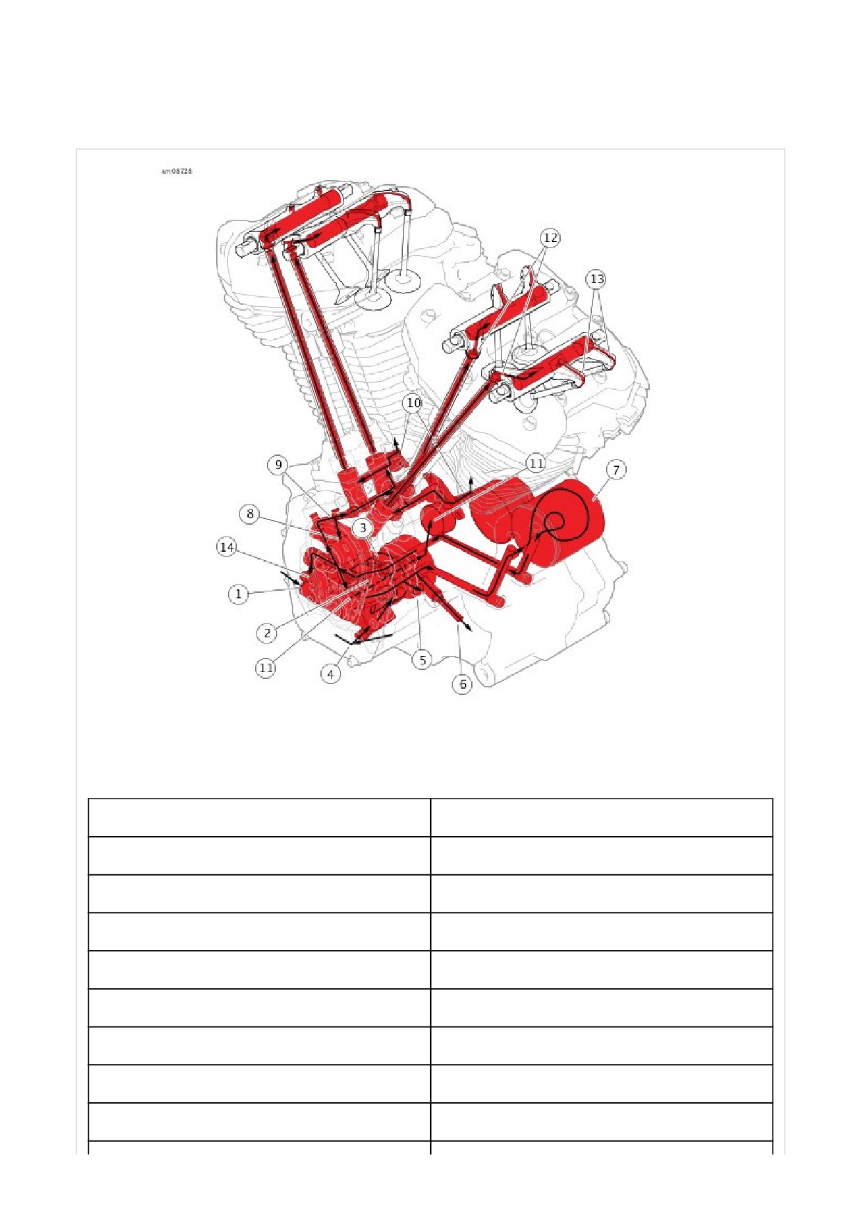
Milwaukee-Eight engines are dry sump engines meaning that they have external oil reservoirs. Air cooled engines have an
oil cooler and circulate oil between the exhaust ports for additional heat control.
1
Oil in from oil pan
2
Oil pump feed rotors
3
Oil pump scavenge rotors
4
Scavenge oil in from cam chest
5
Oil pressure switch
6
Oil out to oil cooler (oil cooled only)
7
Oil filter
8
Cam plain bearing
9
Oil to camshaft, lifters and piston jets
10
Piston jets
11
Oil through crankshaft to crankpin and rod bearings
12
Oil through pushrods to rocker arms
13
Oil spillover to lubricate valve stems
14
Hydraulic chain tensioner
Figure 1. Internal Engine Oil Flow
Internal Oil Distribution: All
1.
See Figure 1.
a.
Oil from the oil pan (1) is pulled through ports in the
oil pan (not shown), the transmission housing and
crankcase
b.
Oil enters the oil pump feed gerotors.
c.
Oil exits the pump and passes oil pressure switch
(5) and oil cooler port (6) headed to oil filter (7). Oil
cooler port is plugged on Twin-Cooled engines.
d.
Oil exits filter and is directed back into cam support
plate where its split between crankshaft, hydraulic
chain tensioner (14), and lifters (9).
e.
Crankshaft oil travels through crankshaft to the
crankpin and rod bearings (11).
f.
Flow toward lifters splits to cam plain bearing (8),
lifters and on to piston jets (10).
g.
Oil flows from lifters up through pushrods to rocker
arms (12).
h.
Oil exits rocker arms to lubricate valve stems via
spillover (13).
i.
Oil drains through passages in the heads and
cylinders back to the camchest cavity. Residual oil in
the camchest cavity and the crankcase cavity is
picked up by the scavenge port (4) in the pump.
Return oil is fed through the scavenge gerotors and
case passages back to the oil pan.
j.
Main bearings, balancer bearing and left cam
bearing are lubricated by oil splash.
1
Oil out check valve
2
Hose, engine to oil cooler
3
Oil cooler
4
Manifold
5
Hose, oil cooler to supply line
6
Supply oil line
7
Passages around exhaust ports
8
Return oil line
9
Oil return line to transmission
10
Connection to engine oil passage in transmission
11
Return oil to oil pan
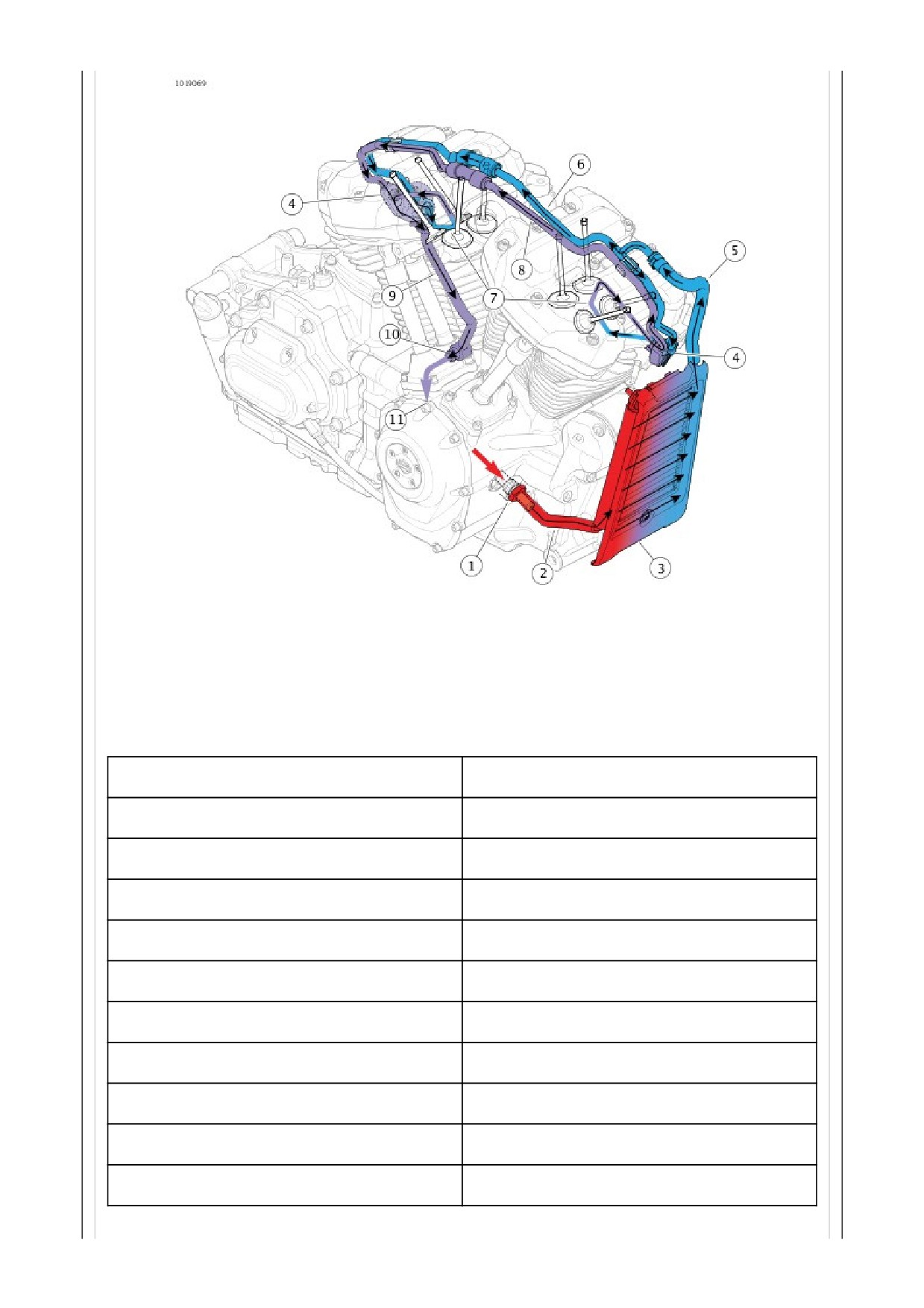
Figure 2. External Engine Oil Flow: Air Cooled
External Oil Distribution: Air Cooled Only
1. See Figure 2.
a. Pressurized oil exits crankcase and flows through
check valve (1), hose (2) to oil cooler (3).
b. Oil flows through oil cooler, hose (5) to oil supply
line (6).
c. Oil flow splits at oil supply line (6) and flows to
manifolds (4).
d. Oil flows through passages between the exhaust
ports (7) in cylinder heads and back to manifolds.
e. Oil flows through return line (8) to return oil line to
transmission (9).
f. Return fitting (10) connects to a passage in
transmission where it returns to the oil pan (11).
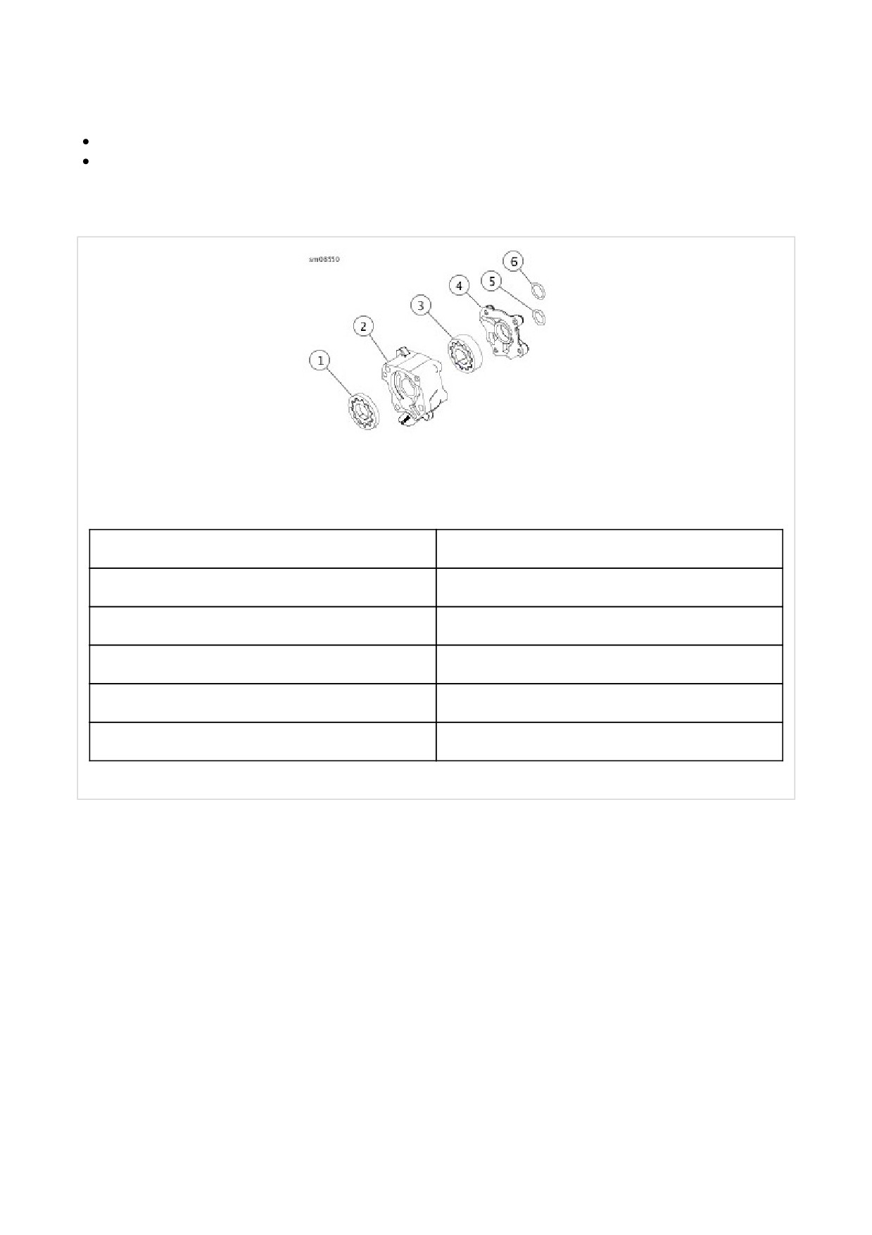
See Figure 1. The oil pump has two gerotor gear sets driven by the crankshaft.
The feed gerotor set distributes oil to the engine.
The scavenge gerotor set draws oil from the cam and flywheel compartments and returns it to the oil pan.
Each gerotor gear set has an inner and outer gerotor. The inner and outer gerotors have fixed centers that are slightly
offset to one another. Also, the inner gerotor has one less tooth.
1
Feed gerotor
2
Housing
3
Scavenge gerotor
4
Inner cover
5
Scavenge port O-ring
6
Feed port O-ring
Figure 1. Oil Pump
The oil pump is driven by the crankshaft. The inlet and outlet sides of the pump are sealed by the tips and lobes of the
inner and outer gerotors. This prevents oil on the outlet side (high pressure) from being transferred to the inlet side.
1
Oil in
2
Seal
3
Outer gerotor
4
Inner gerotor
Figure 1. Inlet Side Oil Flow
1
Seal
2
Oil out
3
Continuous flow
Figure 2. Outlet Side Oil Flow
See Figure 1. As the gerotors rotate, the cavity volume increases between the inner and outer gerotors on the inlet side of
the pump. This creates a vacuum causing oil to be drawn in. The cavity increases until the volume is equivalent to that of
the missing tooth on the inner gerotor.
See Figure 2. As the oil moves to the outlet side of the pump, the cavity decreases in volume. This forces pressurized oil
out the discharge port. In operation, the gerotors provide a continuous flow of oil.
A breather assembly is mounted to each cylinder head to prevent a buildup of pressure caused by the downward force of
the pistons. Burning crankcase vapor eliminates the pollutants normally discharged from the crankcase.
See Figure 1. As pistons push downward, displaced air in the crankcase is vented through the crankshaft roller bearing
into the cam compartment. The air flows up the pushrod covers (1) into the rocker housing. The moving air absorbs a
small amount of oil vapor as it travels through the engine.
The oil/air vapor passes through an opening in the breather assembly (3).
In the breather assembly, the flow of air passes downward through a labyrinth where most of the oil is separated from the
air. It then moves upward through the breather element (4) where the remaining oil is removed. Two small holes in the
bottom of the breather housing allow the separated oil to drain back into the crankcase.
Passing through the breather element, the vapor passes through the umbrella valve (2). Vapor passes down into the
cylinder head passageway and through the breather bolt (5). It passes through a breather tube (6) into the air filter
element where it combines with the intake air stream and is burned during normal combustion.
1
Pushrod cover
2
Umbrella valve
3
Breather assembly
4
Breather element
5
Breather bolt
6
Breather tube
Figure 1. Breather Air Flow
See Figure 1. The red OIL PRESSURE indicator lamp illuminates to indicate improper pressure of the engine oil. The lamp
illuminates when the ignition is initially turned on (before the engine is started), but should extinguish once the engine is
running.
NOTICE
If the oil pressure indicator lamp remains lit, always check the oil supply first. If the oil supply is normal and the lamp is
still lit, stop the engine at once and do not ride further until the trouble is located and the necessary repairs are made.
Failure to do so may result in engine damage. (00157a)
If the indicator lamp does not extinguish, it may be caused by low oil level or diluted oil supply. In freezing weather, the oil
feed and return lines can clog with ice or sludge. Other conditions that may cause the lamp to remain lit are:
Faulty lamp wiring
Faulty oil pressure sending unit
Damaged oil pump
Plugged oil filter element
Incorrect oil viscosity for the operating temperature
Fractured or weak spring in the oil pressure relief valve
Incorrectly installed O-rings in the engine
To troubleshoot the problem, always check the engine oil level first. If the oil level is OK, determine if oil returns to the oil
pan. If oil does not return, shut off the engine until the problem is located and corrected.
Figure 1. Oil Pressure Indicator Lamp (Typical)
Special Tools
Description
Part Number
Qty.
OIL PRESSURE TEST GAUGE KIT
HD-96921-52D
1
1. Verify that engine oil is at the proper level. See Check Engine Oil Level.
2. Run motorcycle until engine oil reaches at least 93.5 °C (200 °F). Stop engine.
3. Remove oil pressure switch from crankcase. See Prepare.
4. See Figure 1. Install OIL PRESSURE TEST GAUGE KIT (Part Number:HD-96921-52D).
a. Hand-tighten adapter HD-96921-106 (2) in oil pressure switch mounting hole.
b. Assemble banjo bolt (3), washer (4), oil pressure gauge (1), banjo fitting and second washer onto adapter.
Hand-tighten.
5. Check oil pressure.
a. Operate engine at various speeds.
b. Record results.
c. Stop engine.
6. Remove oil pressure gauge assembly.
7. Install oil pressure switch. See Prepare.
8. Verify that oil pressure is within specifications. Refer to Table 1.
Table 1. Oil Pressure
CHECK
SPECIFICATION *
SAE
METRIC
Oil pressure - min at idle
5 psi
34.5 kPa
Oil pressure - normal at 2000 rpm
30-38 psi
207-262 kPa
Oil pressure - max
50 psi
345 kPa
* With oil at normal operating temperature of 110 °C (230 °F)
1
Gauge
2
Adapter
3
Banjo bolt
4
Washer (2)
Figure 1. Oil Pressure Gauge Set
Typical Symptoms
Symptoms indicating a need for engine repair are often misleading. If more than one symptom is present, possible
causes can be narrowed to make at least a partial diagnosis.
For example, an above normal consumption of oil could be caused by several mechanical faults. However when
accompanied by blue-gray smoke from the exhaust and low compression, it indicates the rings need replacing. Low
compression by itself is more likely to be caused by improperly seated or burned valves, not worn rings.
Certain knocking noises may occur because of loose bearings, others by piston slap. Piston slap is a condition where
piston or cylinder or both are out of tolerance. This excessive clearance allows the piston to slap the cylinder as it
moves up and down.
Most frequently, valves, rings, pins, bushings and bearings need attention at about the same time. If the symptoms
indicate that any one of the above components is worn, service all related parts.

Special Tools
Description
Part Number
Qty.
CYLINDER COMPRESSION
HD-33223-1
1
GAUGE
BORESCOPE
HD-50549
1
Check for cylinder leakage with a compression test. Use CYLINDER COMPRESSION GAUGE (Part Number:HD-33223-
1) with a screw-in type adapter.
1.
Remove all spark plug cables.
2.
Remove one spark plug from each cylinder.
NOTE
Never use a metal object to hold the throttle plate
open.
3.
Open throttle plate.
a. Remove air cleaner cover and filter. See Remove.
b. Disconnect TCA connector [211] from the induction
module.
c. Insert a 19 mm (0.75 in) diameter by 30.5 cm (12 in)
long wooden or nylon dowel to hold the throttle valve
open.
4.
Test compression.
a. Connect compression tester to front cylinder following
manufacturer's instructions.
b. Crank engine continuously through 5-7 full
compression strokes.
c. Note gauge readings at the end of the first and last
compression strokes. Record test results.
d. Disconnect ACR and repeat test.
e. Connect ACR.
f. Repeat steps (a-e) on rear cylinder.
5.
Compare with specifications. Refer to Table 1
a. If compression is within specifications and the
variance between cylinders is less than 10%,
compression is normal.
b. If readings do not meet specifications, inject 15 ml
(0.5 fl oz) engine oil into each cylinder and repeat the
compression tests on both cylinders. Readings that
are considerably higher during the second test
indicate worn piston rings.
c. Refer to Table 2 for possible causes of low
compression.
d. Inspect cylinder using borescope. Refer to Clean and