Harley Davidson 2018 softail models. Service manual - page 10

4
Hand lever bracket
5
Pin
6
Clutch hand lever
7
Retaining ring
8
Clutch cable
9
Lever bracket clamp
Figure 7. Clutch Assembly
1. Inspect clutch lever and cable for wear or damage.
Replace or repair as necessary.
2. Inspect clutch cable. Replace as necessary.
NOTICE
The clutch control cable must be oiled and adjusted
periodically to compensate for lining wear. See
MAINTENANCE SCHEDULING in this manual.
Failure to oil and adjust the clutch control cable can
result in equipment damage. (00203b)
3. Lubricate clutch cable and hand lever pivot pin hole with
HARLEY LUBE.

Clutch Cable: Lower End
1. Install clutch cable.
a. Connect clutch cable at release cover. See
Prepare.
b. Connect clutch cable. See Clutch Cable Disconnect
in this section.
Clutch Cable: Upper End
1. See Clutch Assembly. Install clutch cable.
a. Install clutch cable (8).
b. Install pin (5).
c. Install clutch hand lever (6).
d. Install pivot pin (3)
e. Install retaining ring (7).
f. Connect clutch cable. See Clutch Cable Disconnect
in this section.
Clutch Cable Connect
1. See Lower Clutch Cable. Install lower clutch cable (2)
into housing (1).
2. See Coupler Disengagement. Pull clutch cable
swaged ball end (2) out slightly from window and then
manipulate clutch lever to align coupler (1) with
swagged ball end and then release.
3. See Retaining Clips. Secure locking tab (1) swaged
ball end (2).
NOTE
Replace upper clutch cable if locking tab is
damaged or missing.
4. See Clutch Assembly. Ensure clutch lever (6) is in full
open position and that ferrule is correctly seated in
housing.
5.
NOTE
Inspect lock button (2). Replace if damaged.
See Compressed Upper Clutch Cable. Disengage
lock button (2) allowing upper clutch cable spring to set
free-play at clutch lever.
6. See Lock Button. Push in lock button (2).
7. Check clutch operation.
8. See Clutch Cover and Clip. Slide cover (2) down and
install spring clips (1).
Clutch Hand Control
1. See Clutch Assembly. Install clutch hand control
assembly.
a. Install hand lever bracket (4).
b. Install lever bracket clamp (9).
c. Install washers (2) and screws (1). Tighten.
Torque: 6.8-9 N·m (60-80 in-lbs) Clutch cable
lever screw

Lock Button
1. See Clutch Cover and Clip. Access two piece clutch
cable.
a.
Remove spring clips (1).
b.
Slide cover (2) up.
2.
NOTE
Upper clutch cable (1) spring must be
uncompressed.
See Upper Clutch Cable Compressed. Unlock upper
clutch cable (1).
a. Place flat side of a screwdriver (5) on tab of the lock
button (2).
b. Push tab slightly inboard and then down to
disengage.
3. Remove lock button.
Housing
1. Disconnect clutch cable. See Clutch Cable Disconnect
in the this section.
2. See Upper Clutch Cable Compressed. Remove
housing (4) from upper housing (3).
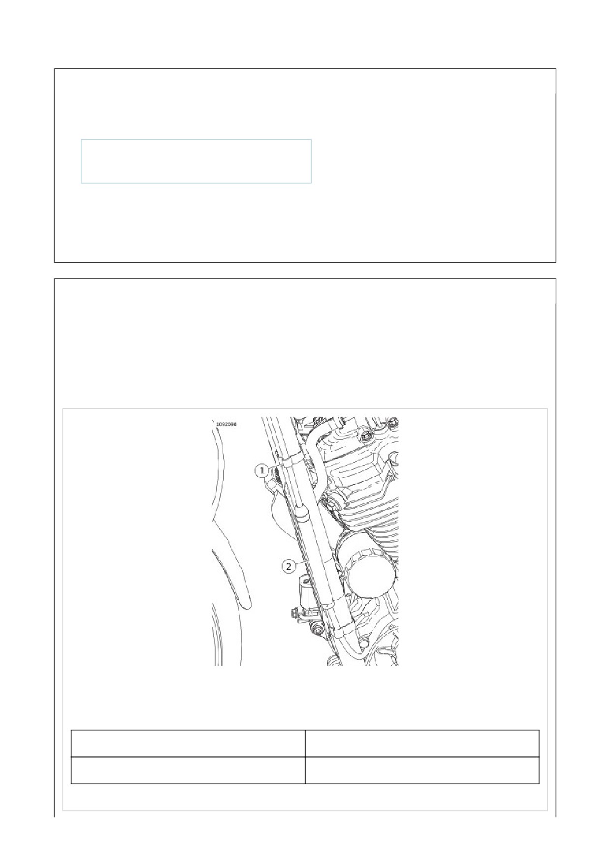
Lock Button
1.
NOTE
Upper clutch cable (1) spring must be
uncompressed.
See Figure 2. Install lock button (2).
2. See Figure 1. Slide cover down (2) and install spring
clips (1).
Housing
1. See Figure 3. Align coupler guide (2) with the guide in
housing.
2. See Figure 2. Install housing (4) to upper housing (3).
3. Connect clutch cable. See Clutch Cable Disconnect in
the this section.
1
Clip
2
Cover
Figure 1. Clutch Cover and Clip
1
Upper clutch cable
2
Lock button
3
Upper housing
4
Housing
5
Screwdriver
Figure 2. Upper Clutch Cable Compressed

1
Upper housing
2
Coupler guide
3
Locking tab
Figure 3. Upper Housing
1. Install main fuse. See Main Fuse.
PREPARE
1. Remove main fuse. See Main Fuse.
2. FLDE and FLHC/S: Remove headlamp. See Bulb
Replacement: Standard Round.

HORIZONTAL
1. See Bulb Replacement: Standard Round.
STANDARD ROUND
1. See Standard Round Nacelle and Standard Round
Rear View. Remove screws (1) and clamps (2).
2. See Standard Round Nacelle. Remove screws (3).
3. Remove trim cover (4).
4. Remove left and right cover (5 and 6).
5. Remove nacelle (7).
NACELLE MOUNTED
1. See Nacelle Mounted. Remove screw (6).
2.
NOTE
Bezel is under pressure from isolators (7),
disassemble slowly.
Remove bezel (5).
3. Remove screws (8) and washers (9).
4. Remove screws (3).
5. Remove left and right cover (2 and 1).
6. Remove nacelle (4).
Consumables
Description
Part Number
Size
LOCTITE 243 MEDIUM STRENGTH
99642-97
6 ml (¼ fl oz)
THREADLOCKER AND SEALANT
(BLUE)
HORIZONTAL
1. See Bulb Replacement: Standard Round.
STANDARD ROUND
1. Inspect upper and lower pads. Replace as needed.
2. See Figure 1. Install nacelle (7), right cover (6) and trim
strip (2).
3. Apply threadlocker and install screws (3). Tighten.
Torque: 9.4-12.2 N·m (83-108 in-lbs) Headlamp
nacelle trim strip screw
LOCTITE 243 MEDIUM STRENGTH
THREADLOCKER AND SEALANT (BLUE) (99642-97)
4. Install left cover (5) and trim strip (4).
5. Install screws (3). Tighten.
Torque: 9.4-12.2 N·m (83-108 in-lbs) Headlamp
nacelle trim strip screw
6. See Figure 1 and Figure 2. Install clamps (2) and
screws (1). Tighten.
Torque: 4.06-5.42 N·m (36-48 in-lbs) Headlamp
nacelle clamp screw
1
Screw (2)
2
Clamp
3
Screw (4)
4
Trim strip (2)
5
Left cover
6
Right cover
7
Nacelle
Figure 1. Standard Round Nacelle
1
Screw
2
Clamp
Figure 2. Standard Round Rear View
NACELLE MOUNTED
1. See Figure 3. Inspect trim strip (10). Replace if
necessary. See Remove.
2. Install nacelle (4) and right cover (1).
3. Apply threadlocker and install screws (3). Tighten.
Torque: 9.4-12.2 N·m (7-9 ft-lbs) Headlamp nacelle
cover screw
LOCTITE 243 MEDIUM STRENGTH
THREADLOCKER AND SEALANT (BLUE) (99642-97)
4. Install left cover (2).
5. Install screws (3). Tighten.
Torque: 9.4-12.2 N·m (7-9 ft-lbs) Headlamp nacelle
cover screw
6. Install washers (9) and screws (8). Tighten.
Torque: 9.6-11.7 N·m (85-104 in-lbs) Headlamp
nacelle screw
7. Install bezel (5). Insert gasket behind lip of bezel.
8. Install screw (6). Tighten.
Torque: 2.8-3.6 N·m (25-32 in-lbs) Headlamp, nacelle
mounted, bezel screw
1
Right cover
2
Left cover
3
Screw (4)
4
Nacelle
5
Bezel
6
Screw
7
Isolator (2)
8
Screw (2)
9
Washer (2)

10
Trim strip
Figure 3. Nacelle Mounted
COMPLETE
1. FLDE and FLHC/S: Install headlamp. See Bulb
Replacement: Standard Round.
2. Install main fuse. See Main Fuse.
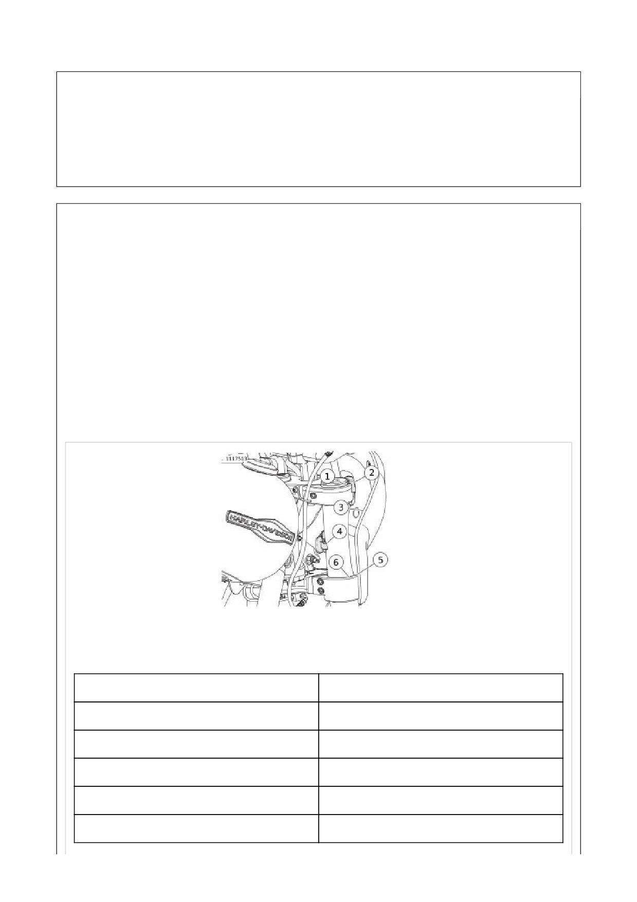
Removal
1. See Figure 1. Remove fairing.
a. Open clamps (4).
b. Lift fairing (3) up over headlamp.
Installation
1. See Figure 2. Install fairing.
a. Open clamps (4).
b. Place fairing over headlamp and onto front forks (5).
c. Verify there are no cables or wires pinched.
d. See Figure 1. Position upper bumper (2) on upper
fork bracket (1).
e. Verify lower bumper (5) is seated on lower fork
bracket (6).
f. Lock clamps.
g. Verify the upper bumpers and lower bumpers are
properly seated and fairing is secure.
1
Upper fork bracket
2
Upper bumper
3
Fairing
4
Clamp
5
Lower bumper
6
Lower fork bracket
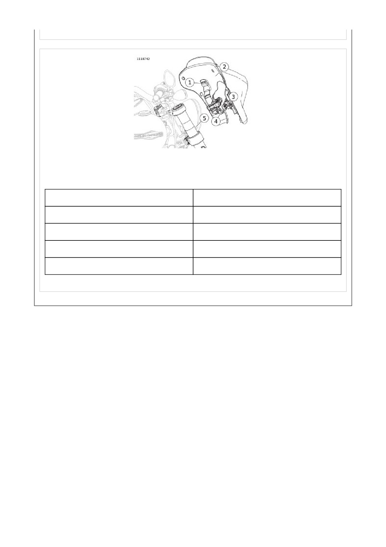
Figure 1. Fairing Installed
1
Inner fairing bumper (8)
2
Inner fairing
3
Clamp bumper (2)
4
Clamp (2)
5
Front fork (2)
Figure 2. Fairing Clamps
Disassemble
1. See Figure 2. Remove inner fairing.
a. Remove fairing.
b. Remove screws (7).
c. Separate inner fairing (1) from outer fairing (3).
d. Remove clips (2) if needed.
2. Remove clamps.
a.
Remove pins (4).
b.
Remove clamps (6).
3. See Figure 1. Remove windshield.
a. Loosen screws (3).
NOTE
Do not remove screws.
b. Lift windshield (2) from inner fairing (1).
Assemble
1. See Figure 1. Install windshield.
a. Slide windshield (2) onto screws (3).
b. Verify the windshield is properly seated. Tighten.
Torque: 3.6-4.5 N·m (32-40 in-lbs) Fairing
windshield screw
2. See Figure 2. Install clamps.
a. Place clamps (6) in position on inner fairing (1).
b. Install pins (4) through holes on inner fairing and
through clamps until flush.
c. Verify operation of clamps.
3. Install inner fairing.
a. Place inner fairing (1) and outer fairing (3) together.
b. Install screws (7).
c. See Figure 3. Tighten screws in sequence shown.
Torque: 3.6-4.5 N·m (32-40 in-lbs) Fairing, inner
screw
1
Inner fairing
2
Windshield
3
Screws (2)
Figure 1. Quick Disconnect Fairing Windshield
1
Inner fairing
2
Clip (7)
3
Outer fairing
4
Pin (4)
5
Bumper (8)
6
Clamp (2)
7
Screw (7)
Figure 2. Quick Disconnect Fairing
Figure 3. Torque Sequence
1. See Windshield. Remove windshield.
a. Grab windshield at either side of horizontal bracket
(2).
b. Pull windshield so that upper notches (1) separate
from grommets.
c. Raise windshield until lower notches (5) separate
from grommets.
d. Remove windshield.
1. See Windshield. Install windshield.
a. Place upper and lower notches (1,5) on upper and
lower grommets.
b. Push evenly on horizontal bracket (2) until notches
are fully seated on grommets.
1
Upper notch (2)
2
Horizontal bracket
3
Vertical bracket
4
Windshield
5
Lower notch (2)
Figure 1. Windshield
1. See Windshield Assembly. Disassemble windshield
brackets.
a. Place windshield on a clean padded surface.
b. Remove acorn nuts (2) and discard screws (6, 7) from
each vertical bracket (8).
c. Remove and discard remaining screws from
horizontal bracket (5).
1. See Windshield Assembly. Install horizontal bracket.
a. Position inner horizontal bracket (3) and outer
horizontal bracket (5) on windshield (4).
b. Loosely install three new short screws (6) and acorn
nuts (2).
2. Install vertical bracket.
a. Position mounting brackets (1) and vertical brackets
(8) on windshield.
b. Loosely install new long screws (7) and new short
screws (6) through vertical brackets, windshield and
mounting brackets.
c. loosely install acorn nuts.
d. Tighten all nuts.
Torque: 2.6-3 N·m (23-27 in-lbs) Windshield acorn
nuts
1
Mounting bracket (2)
2
Acorn nut (9)
3
Inner horizontal bracket
4
Windshield

5
Outer horizontal bracket
6
Short Screw (7)
7
Long screw (2)
8
Vertical bracket
Figure 1. Windshield Assembly
Left
1. Remove LHCM. See Prepare.
2. Remove left hand grip.
a. Cut hand grip open with a sharp knife.
b. Peel hand grip open.
c. Remove from handlebar.
Right
1. Remove RHCM. See Prepare.
2. Remove right hand grip.

Consumables
Description
Part Number
Size
HARLEY-DAVIDSON ADHESIVE
99839-95
29.6 ml (1 fl oz)
(GRIPLOCK)
LOCTITE 770 PRISM PRIMER
Loctite 770
-
Left
1. Install left hand grip.
NOTE
Adhesive sets in 4 minutes and cures in 24 hours.
a. Prepare the left grip end of the handlebar with
emery cloth.
b. Clean the left grip end of the handlebar with
acetone.
c. Apply primer to the inside of the new hand grip.
LOCTITE 770 PRISM PRIMER (Loctite 770)
d. Remove excess primer. Wait 2 minutes for the
primer to set.
e. Apply adhesive to the inside of the new hand grip.
HARLEY-DAVIDSON ADHESIVE (GRIPLOCK)
(99839-95)
f. Install the new hand grip with a twisting motion,
ending with cosmetic features properly positioned.
2. Install LHCM. See Prepare.
Right
1. Install hand grip with cosmetic features properly
positioned.
a. Rotate to verify that internal splines are engaged
with the twist grip sensor.
2. Install RHCM. See Prepare
1. Remove main fuse. See Main Fuse.
2. Remove windshield, if equipped. See Remove.
3. Remove fairing, if equipped. See Remove and Install.
4. Remove front brake master cylinder. See Prepare.
5. Disconnect RHCM, TGS, and LHCM from front electrical
caddy. See Prepare.
6. Remove clutch cable from clutch hand lever. See
Prepare.
1. Remove handlebar assembly. See Handlebar Mounting
(Typical).
a. Remove flange nuts (11) and lower cup washers (10).
b. FXBB, FXBR, FXBRS Disconnect IM. See General.
c. Remove handlebar (1) and attached components as
an assembly.
1. Install handlebar assembly. See Handlebar Mounting
(Typical).
a. Place upper cup washers (6) on top of bushings (7).
b. Install studs (5) through upper cup washers (6),
bushings (7), spacers (8), and upper fork bracket (9).
c. Install lower cup washers (10) and flange nuts (11).
Tighten flange nuts.
Torque: 40.7-54.3 N·m (30-40 ft-lbs) Riser flange
nuts
d. FXBB, FXBR, FXBRS Connect IM. See General.
1
Handlebar
2
Handlebar clamp
3
Handlebar clamp fastener (4)
4
Riser (2)
5
Stud (2)
6
Upper cup washer (2)
7
Bushing (4)
8
Spacer (2)

9
Upper fork bracket (typical)
10
Lower cup washer (2)
11
Flange nut (2)
Figure 1. Handlebar Mounting (Typical)
1. Remove RHCM. See Prepare.
2. Remove TGS. See Prepare.
3. Remove clutch hand control. See Prepare.
4. Remove LHCM. See Prepare.
5. Remove left hand grip, if necessary. See Remove.
6. FXBR, FXBRS, FXFB, FXFBS, FLFB, FLFBS Remove
weight inside left handlebar, if necessary.
7. Disassemble handlebar assembly. See Handlebar
Mounting (Typical).
a. Remove handlebar clamp fasteners (3) to separate
the handlebar (1), handlebar clamp (2), and risers
(4).
b. Remove studs (5) from riser, if necessary.
c. Remove spacers (8) and bushings (7), if necessary.
1.
Assemble handlebar assembly. See Handlebar Mounting
(Typical).
a.
Install bushings (7) and spacers (8), if removed.
b.
Thread the short end of studs (5) into risers (4) until
bottomed, if removed.
c.
Install upper cup washer (6) on top of left and right
bushings (7).
d.
Insert studs in bushings and install lower cup washer
(10) and flange nut (11) loosely.
e.
Center handlebar (1) in risers.
f.
Place handlebars in normal riding position and hold.
g.
Attach handlebar clamp (2) with handlebar clamp
fasteners (4).
NOTE
Tighten handlebar clamp fasteners just enough to
maintain handlebar position.
h.
Tighten gap limiting fasteners.
Torque: 16.3-21.7 N·m (12-16 ft-lbs) Handlebar
clamp gap limiting fasteners
NOTE
Handlebar clamps are manufactured with pads on
one half of the top clamp that should be touching
the riser when assembled. The fasteners (gap
limiting fasteners) closest to the pads need to be
tightened first.
i.
Tighten open gap fasteners. Verify that there is a gap
between upper and lower clamps at front.
Torque: 16.3-21.7 N·m (12-16 ft-lbs) Handlebar
clamp open gap fasteners
j.
Tighten flange nuts (11).
Torque: 40.7-54.3 N·m (30-40 ft-lbs) Riser flange
nuts
2.
FXBB, FXBR, FXBRS Connect IM. See General.
3.
FXBR, FXBRS, FXFB, FXFBS, FLFB, FLFBS Install
weight inside left handlebar, if necessary.
4.
Install left hand grip, if necessary. See Remove.
5.
Install LHCM. See Prepare.
6.
Install clutch control. See Prepare.
7.
Install TGS. See Prepare.
8.
Install RHCM. See Prepare.
1. Connect clutch cable to clutch lever. See Prepare.
2. Connect RHCM, TGS, and LHCM to front electrical caddy.
See Prepare.
3. Install front brake master cylinder. See Prepare.
4. Install fairing, if equipped. See Remove and Install.
5. Install windshield, if equipped. See Remove.
6. Install main fuse. See Main Fuse.
Remove
1. See Mirror Mount (Typical). Support turn signal
assembly (2), if equipped.
2. Remove nut (4) and washer (3).
3. Remove mirror (1).
Install
1. See Mirror Mount (Typical). Insert threaded stem of
mirror into hole in clutch or brake lever bracket.
2. Install turn signal (2), if equipped.
3. Install washer (3) and nut (4).
4. Adjust mirror as necessary and tighten nut.
Torque: 10.8-16.3 N·m (96-144 in-lbs) Mirror mounting
nut
1
Mirror
2
Turn signal assembly, if equipped
3
Lock washer
4
Nut
Figure 1. Mirror Mount (Typical)
1. See Front Fenders. Remove front fender.
a. Remove screws (3,5,7) and nuts (8), depending on
model.
b. Remove fender (2,4,6), depending on model.
c. FXFB, FXFBS: Fender (2) assembly, remove screws
(1) and nuts (9). Separate from bracket (10).

Consumables
Description
Part Number
Size
LOCTITE 243 MEDIUM STRENGTH
99642-97
6 ml (¼ fl oz)
THREADLOCKER AND SEALANT
(BLUE)
FXFB, FXFBS
1. See Front Fenders. Install front fender.
a. Align fender (2) with bracket (10).
b. Apply threadlock to screws (1).
LOCTITE 243 MEDIUM STRENGTH
THREADLOCKER AND SEALANT (BLUE)
(99642-97)
c. Install screws and nuts (9). Tighten.
Torque: 4.1-5.4 N·m (36-48 in-lbs) Front fender to
bracket screw, FXFB/FXFBS
d. Align fender assembly with mounting holes on front
fork.
e. Apply threadlock to screws (3).
LOCTITE 243 MEDIUM STRENGTH
THREADLOCKER AND SEALANT (BLUE)
(99642-97)
f. Install screws. Tighten.
Torque: 8-10 N·m (71-89 in-lbs) Front fender
mounting screw, FXFB/FXFBS
FXBB
1. See Front Fenders. Install front fender.
NOTE
Verify that the mounting brackets are resting against
the machined bosses of the forks before tightening.
a. Align fender (6) mounting brackets to the machined
bosses on the front forks.
b. Apply threadlock to screws (7).
LOCTITE 243 MEDIUM STRENGTH
THREADLOCKER AND SEALANT (BLUE)
(99642-97)
c. Install Screws and nuts (8). Tighten.
Torque: 22-28 N·m (16-21 ft-lbs) Front fender
mounting screw, FXBB
Front Fender (Typical)
1. See Front Fenders. Install front fender.
a. Align fender (4) to the mounting holes on fork.
b. Apply threadlock to screws (5).
LOCTITE 243 MEDIUM STRENGTH
THREADLOCKER AND SEALANT (BLUE)
(99642-97)
c. Install Screws. Tighten.
Torque: 22-28 N·m (16-21 ft-lbs) Front fender
mounting screw (typical)
1
Screw (4)
2
Fender, FXFB/FXFBS
3
Screw (4)
4
Fender (typical)
5
Screw (4)
6
Fender, FXBB
7
Screw (4)
8
Nut (4)