Harley Davidson 2018 softail models. Service manual - page 7
Consumables
Description
Part Number
Size
CCI #20 BRAKE GREASE
42830-05
29.6 ml (1 fl oz)
G40M BRAKE GREASE
42820-04
29.6 ml (1 fl oz)
Disassemble
1.
NOTE
Install a new rebuild kit when unit is reassembled.
See Figure 1. Remove cover.
a.
Remove cover screws (3).
b.
Remove cover (5).
c.
Remove reservoir gasket (2).
2.
Remove piston set (1).
a. Hold nut (18). Remove yoke (20).
b. Remove return spring boot (19).
c.
WARNING
Wear safety glasses or goggles when removing
or installing retaining rings. Retaining rings can
slip from the pliers and could be propelled with
enough force to cause serious eye injury.
(00312a)
Remove nut (18), spring retainer (17) and return
spring (16).
d. Remove boot (15).
e. Remove retaining ring (14) and pushrod assembly
(13, 12 and 11).
f. Remove piston assembly (9 and 10).
g. Remove spring (7) and primary cup (8).
3.
Discard piston set.
1
Piston set
2
Reservoir gasket
3
Cover screw (2)
4
Decal
5
Cover
6
Screw (2)
7
Spring
8
Primary cup
9
Piston
10
Secondary cup
11
Push rod
12
Stop plate
13
Boot collar
14
Retaining ring
15
Boot
16
External return spring
17
Spring retainer
18
Nut
19
Return spring boot
20
Yoke
Figure 1. Rear Master Cylinder Assembly
Clean and Inspect
WARNING
Use denatured alcohol to clean brake system components. Do not use mineral-based solvents (such as gasoline
or paint thinner), which will deteriorate rubber parts even after assembly. Deterioration of these components can
cause brake failure, which could result in death or serious injury. (00291a)
1.
NOTE
Do not use wire or similar tool to clean drilled
passages.
Clean all metal parts, except the cartridge body
assembly, and blow dry with compressed air. Clean all
rubber parts using denatured alcohol.
2. Inspect the cylinder bore for scratches. Replace the
master cylinder assembly if scratches are present.
3. Inspect O-ring grooves on the cartridge body for dirt.
Carefully clean O-ring grooves using a soft cotton cloth
moistened with alcohol and allow to dry. Inspect O-ring
grooves for scratches. Replace cartridge body if
grooves are scratched.
4. Inspect the reservoir cover gasket for cuts, tears or
general deterioration.
Assemble
1.
NOTE
When assembling rear brake master cylinder,
always use new parts from the service parts kit.
See Figure 1. Install new piston set (1).
a. Apply grease to cylinder bore, piston (9) and cups
(8 and 10).
CCI #20 BRAKE GREASE (42830-05)
b.
Install primary cup (8) on small end of spring (7).
c.
Insert large end of spring first. Install spring and
cup into cylinder bore.
d.
Insert flat end of piston first. Install piston and cup
into cylinder bore.
e.
Lightly apply grease to ball end of the pushrod
assembly.
G40M BRAKE GREASE (42820-04)
f.
Install ball end of pushrod into cupped end of
piston.
g.
Compress piston with pushrod.
h.
WARNING
Wear safety glasses or goggles when
removing or installing retaining rings.
Retaining rings can slip from the pliers and
could be propelled with enough force to cause
serious eye injury. (00312a)
Install retaining ring (14). Verify that retaining ring
is completely seated in groove.
i.
Install boot (15) over pushrod and into end of
master cylinder bore. Press lip of inner boot down
around groove in boot collar (13).
j.
Install external return spring (16).
k.
Compress return spring and Install spring retainer
(17) and nut (18).
l.
See Figure 2. Tighten nut to 48.8 mm (1.9 in) from
face of master cylinder to end of hex nut.
m.
See Figure 1. Install return spring boot (19).
Position boot taps at 3 o'clock and 9 o'clock
position when master cylinder body is held upright.
n.
Hold nut and install yoke (20). Tighten.
Torque: 14.7-19.6 N·m (11-14 ft-lbs) Master brake
cylinder yoke
Figure 2. 1.92 in (48.8 mm)
1. If removed: Install right footboard/footpeg bracket. See
Remove and Install: Forward Foot Controls.
2. Fill and bleed rear brake system. See Drain.
1. If necessary: Remove muffler. See Prepare.
2. Caliper service only: Drain brake fluid from rear brake
system. See Drain.
CAUTION
Direct contact of DOT 4 brake fluid with eyes can cause irritation. Avoid eye contact. In case of eye contact flush with
large amounts of water and get medical attention. Swallowing large amounts of DOT 4 brake fluid can cause digestive
discomfort. If swallowed, obtain medical attention. Use in well ventilated area. KEEP OUT OF REACH OF CHILDREN.
(00240b)
NOTICE
DOT 4 brake fluid will damage painted and body panel surfaces it comes in contact with. Always use caution and
protect surfaces from spills whenever brake work is performed. Failure to comply can result in cosmetic damage.
(00239c)
NOTE
If DOT 4 brake fluid contacts painted surfaces, IMMEDIATELY flush area with clear water.
1. See Figure 1. Remove slider bolt (5) and sleeve screw
(6).
a.
Clean threads of sleeve screw.
Removing Caliper to Remove Rear Wheel
1. Remove caliper.
a. Slide caliper forward to clear rear brake rotor, and
position out-of-way.
Removing Caliper to Removing Rear Brake Pads
1. Loosen the brake pad hanger pins (7).
2. Remove caliper.
a. Slide caliper forward to clear rear brake rotor, and
position to remove rear brake pads.
Removing Caliper for Service
1. Loosen the brake pad hanger pins (7).
2. Remove banjo bolt (2).
a. Remove banjo bolt.
b. Remove and discard gasket washers (1).
3. Remove caliper.
a. Slide caliper forward to clear rear brake rotor, and
remove rear brake caliper.
1
Gasket washer (2)
2
Banjo bolt
3
Rear brake line
4
WSS (Wheel speed sensor) harness - ABS (Anti-lock
braking system) only
5
Slider bolt
6
Sleeve screw
7
Brake pad hanger pin (2)
Figure 1. Rear Caliper
Remove Rear Caliper Mounting Bracket
1. Remove rear wheel. See Prepare.
2. Remove rear caliper mounting bracket.
a. Inspect for damage or worn parts.
Special Tools
Description
Part Number
Qty.
12MM TORQUE ADAPTER
HD-52351
1
Consumables
Description
Part Number
Size
LOCTITE 242 MEDIUM STRENGTH
Loctite 242
10 ml
THREADLOCKER ADHESIVE
(BLUE)
Install Rear Caliper Mounting Bracket
1. Position rear caliper mounting bracket on rear wheel.
2. Install rear wheel. See Prepare.
Installing Caliper from Service
1.
See Rear Caliper. Install caliper
a. Position caliper on mounting bracket in front of
brake rotor.
b. Slide caliper rearward, guiding the brake pads
around brake rotor.
NOTE
Verify the WSS (Wheel speed sensor) harness
(4) is routed under the caliper mounting
bracket.
c. Align the caliper with the slider bolt hole and sleeve
screw hole.
d. Apply threadlocker to sleeve screw. Install slider
bolt (5) and sleeve screw (6). Hand tighten.
LOCTITE 242 MEDIUM STRENGTH
THREADLOCKER ADHESIVE (BLUE) (Loctite
242)
2.
Install banjo bolt (2).
a. Install banjo bolt, new gasket washers (1) and rear
brake line (3). Tighten.
Torque: 29-31 N·m (21-23 ft-lbs) Rear brake
caliper banjo bolt
3.
Tighten brake pad hanger pins (7).
Torque: 14.7-19.6 N·m (11-14 ft-lbs) Rear brake caliper
pad hanger pin
Installing Caliper from Removing Rear Brake Pads
1. See Rear Caliper. Install caliper
a. Position caliper on mounting bracket in front of
brake rotor.
b. Slide caliper rearward, guiding the brake pads
around brake rotor.
NOTE
Verify the WSS harness (4) is routed under the
caliper mounting bracket.
c. Align the caliper with the slider bolt hole and sleeve
screw hole.
d. Install slider bolt (5) and sleeve screw (6). Hand
tighten.
2. Tighten brake pad hanger pins (7).
Torque: 14.7-19.6 N·m (11-14 ft-lbs) Rear brake caliper
pad hanger pin
Installing Caliper from Remove Rear Wheel
1. See Rear Caliper. Install caliper
a. Position caliper on mounting bracket in front of
brake rotor.
b. Slide caliper rearward, guiding the brake pads
around brake rotor.
NOTE
Verify the WSS harness (4) is routed under the
caliper mounting bracket.
c. Align the caliper with the slider bolt hole and sleeve
screw hole.
d. Install slider bolt (5) and sleeve screw (6). Hand
tighten.
Install All
1. See Figure 1. Using torque adapter.
Special Tool: 12MM TORQUE ADAPTER (HD-52351)
a. See Rear Caliper. Tighten sleeve screw (6).
Torque: 19.6-24.5 N·m (14-18 ft-lbs) Rear caliper
sleeve screw
b. Tighten slider bolt (5).
Torque: 19.6-24.5 N·m (14-18 ft-lbs) Rear caliper
slider bolt
1
12mm Torque Adapter (HD-52351)
2
Banjo bolt
3
Slider bolt
4
Sleeve screw
Figure 1. 12mm Torque Adapter (HD-52351)
Special Tools
Description
Part Number
Qty.
REAR BRAKE PISTION REMOVAL
HD-48648
1
TOOL
Caliper
1. Remove rear brake pads. See Inspect.
WARNING
Compressed air can pierce the skin and flying
debris from compressed air could cause serious
eye injury. Wear safety glasses when working
with compressed air. Never use your hand to
check for air leaks or to determine air flow rates.
(00061a)
2. See Figure 2. Removal pistons (1).
a. Place caliper on working bench.
b. Remove brake pad retaining spring (10).
c. See Figure 1. Using low pressure compressed air
and removal tool, remove pistons and discard.
Special Tool: REAR BRAKE PISTION REMOVAL
TOOL (HD-48648)
1
HD-48648 Rear brake piston removal tool
2
Rear brake caliper
Figure 1. Caliper Piston Removal
3. See Figure 2. Remove seals and discard.
a.
Remove dust seal (2).
b.
Remove piston seal (3).
4. Remove brake caliper sleeve (8).
5. Remove brake caliper sleeve boot (9).
6. Remove bleeder screw cap (5).
7. Remove bleeder screw (4).
8. Remove medallion (7).
1
Piston (2)
2
Dust seal (2)
3
Piston seal (2)
4
Bleeder screw
5
Bleeder screw cap
6
Brake caliper body
7
Medallion
8
Brake caliper sleeve
9
Brake caliper sleeve boot
10
Brake pad retaining spring
Figure 2. Rear Brake Caliper Assembly
Rear Caliper Mounting Bracket
1. See Figure 3. Remove slider pin (5).
2. Remove slider pin dust cover (4).
3. Remove caliper damper (3).
1
Mounting bracket
2
Brake pad retaining clip seat
3
Caliper damper
4
Slider pin dust cover
5
Slider pin
Figure 3. Rear Caliper Mounting Bracket
Consumables
Description
Part Number
Size
DOT 4 BRAKE FLUID
99953-99A
355 ml (12 fl oz)
WARNING
Use denatured alcohol to clean brake system components. Do not use mineral-based solvents (such as gasoline or
paint thinner), which will deteriorate rubber parts even after assembly. Deterioration of these components can cause
brake failure, which could result in death or serious injury. (00291a)
1.
Clean all rubber parts with brake fluid. Do not contaminate
with mineral oil or other solvents. Clean all metal parts
with denatured alcohol. Wipe parts dry with a clean, lint-
free cloth.
DOT 4 BRAKE FLUID (99953-99A)
WARNING
Compressed air can pierce the skin and flying debris
from compressed air could cause serious eye
injury. Wear safety glasses when working with
compressed air. Never use your hand to check for
air leaks or to determine air flow rates. (00061a)
2.
Blow out drilled passages and piston bore with low
pressure compressed air from a clean air supply. Do not
use a wire or similar instrument to clean drilled passages.
3.
Carefully inspect all components. Replace as necessary.
a. Check pistons for pitting, scratches or corrosion on
outside surfaces.
b. Inspect piston bores. Do not hone bores. Replace as
necessary.
NOTE
The pad pins are manufactured with a relief near
the center of their length, where the pad spring
touches. Do not use this area as a measurement
point to determine pad pin wear.
c. Inspect pad pin for grooving and wear at the pad
contact points. Measure the pad pin diameter in an
unworn area and in an area of any grooving or wear.
If wear exceeds 0.28 mm (0.011 in), replace pad pin.
d. Inspect pad spring for wear or cracks. Replace if
necessary.
e. Always replace all seals after disassembly.
WARNING
Always replace brake pads in complete sets for
correct and safe brake operation. Improper brake
operation could result in death or serious injury.
(00111a)
4. Inspect brake pads and brake disc. Replace if necessary.
a. Specifications: content: See Inspect.
b. Brake Disc: See Prepare.
Consumables
Description
Part Number
Size
CCI #20 BRAKE GREASE
42830-05
29.6 ml (1 fl oz)
DOT 4 BRAKE FLUID
99953-99A
355 ml (12 fl oz)
G40M BRAKE GREASE
42820-04
29.6 ml (1 fl oz)
Rear Caliper Mounting Bracket
1. See Rear Caliper Mounting Bracket. Install caliper
damper (3).
2. Apply grease to the inside of slider pin dust cover (4).
G40M BRAKE GREASE (42820-04)
3. Install slider pin dust cover.
4. Install slider pin (5).
Caliper
1.
See Rear Brake Caliper Assembly. Install new
medallion (7). See Remove.
2.
Install bleeder screw (4). Hand tighten.
3.
Install bleeder screw cap (5).
4.
Lightly apply silicone grease to brake caliper sleeve
boot (9).
CCI #20 BRAKE GREASE (42830-05)
5.
Install brake caliper sleeve (8).
NOTICE
Avoid leakage. Prevent damage to piston or
piston bore. Use non-metallic tools when
servicing components. (00529d)
6.
Install piston (1).
a. Apply a light coating of brake fluid over the pistons,
dust seal (2) and piston seal (3).
DOT 4 BRAKE FLUID (99953-99A)
b. See Figure 1. Install the piston seals (3) into the
brake caliper piston bore.
c. Install the dust seals (2) into the brake caliper piston
bore.
d. Insert pistons, by hand, into bores of caliper
housing. Press pistons squarely into place until
they bottom in the bores. If installation shows
resistance, remove piston. Check that seals are
properly installed.
e. Install brake pad retaining spring (10).
1
Wooden toothpick
2
Dust seal
3
Piston seal
Figure 1. Rear Caliper Seals (Typical)
1. If drained: Fill and bleed rear brake system. See Drain.
2. If removed: Install muffler. See Prepare.
Prepare
1. Drain front brake line. See Drain.
Remove
1. Remove brake line (1) from front brake master cylinder. See Prepare.
NOTE
If equipped with dual front calipers, remove brake lines from both calipers.
2. Remove brake line from front brake caliper. See Prepare.
3. See Figure 1. Remove brake line.
a. Remove brake line from wireform (2).
b. Remove cable strap, if equipped.
c. Remove screw (4).
d. Remove brake line.
e. Single caliper: Remove clamp (3) from front brake line.
Install
1. Install brake line (1) to front brake master cylinder. See
Prepare.
2. See Figure 1. Install brake line.
a. Route brake line as shown.
b. Single caliper: Install clamp (3) onto front brake
line.
c. Dual caliper: Position front brake line manifold (5)
d. Install screw (4). Tighten.
Torque: 4.1-5.4 N·m (36-48 in-lbs) Front brake
line screw
3. Install brake line to front brake caliper. See Prepare.
NOTE
If equipped with dual front calipers, install brake
lines to both calipers.
4. Install brake line into wireform (2).
5. Install cable strap, if removed.
Complete
1. Bleed brake system. See Drain.
1
Brake line
2
Wire form
3
Clamp
4
Screw
5
Front brake line manifold
Figure 1. Front Brake Line: Single and Dual Front Caliper (Non ABS)
Consumables
Description
Part Number
Size
LOCTITE 243 MEDIUM STRENGTH
99642-97
6 ml (¼ fl oz)
THREADLOCKER AND SEALANT
(BLUE)
Prepare
1. Remove seat. See Remove.
2. Remove right side cover. See Remove.
3. Remove negative battery cable. See Main Fuse.
4. Remove battery strap. See Prepare.
5. Remove battery. See Prepare.
6. Remove battery tray. See Prepare.
7. Drain rear brake line. See Drain.
8. Remove rear stoplamp switch. See Prepare.
Remove
1. Remove brake line from rear brake master cylinder. See
Prepare.
2. Remove brake line from rear brake caliper. See
Prepare.
3. See Figure 1. Remove rear brake line retaining bracket.
a. Remove screws (1).
b. Remove rear brake line bracket (2).
4. Remove brake line.
a. Remove screws (5).
b. Remove brake line (4).
c. Remove clamps (6) from brake line.
d. Remove grommet (3) from brake line.
Install
1. See Figure 1. Install grommet (3) onto brake line (4).
2. Route brake line as shown.
3. Install brake line at rear brake master cylinder. See
Prepare.
4. Install brake line at rear brake caliper. See Prepare.
5. Install rear brake line retaining bracket.
a. Install rear brake line bracket (2).
b. Install screws (1). Tighten.
Torque: 2.7-4.1 N·m (24-36 in-lbs) Rear brake line
bracket screws
6. Install brake line.
a. Install clamps (6).
b. Apply threadlocker to screws (5).
LOCTITE 243 MEDIUM STRENGTH
THREADLOCKER AND SEALANT (BLUE)
(99642-97)
c. Install screws. Tighten.
Torque: 2.7-4.1 N·m (24-36 in-lbs) Rear brake line
clamp screws
Complete
1. Install rear stoplamp switch. See Prepare.
2. Install battery tray. See Prepare.
3. Install battery. See Prepare.
4. Install negative battery cable. See Main Fuse.
5. Install battery strap. See Prepare.
6. Install right side cover. See Remove.
7. Install seat. See Remove.
8. Bleed brake system. See Drain.
1
Screw (2)
2
Rear brake line bracket
3
Grommet
4
Brake line
5
Screw (3)
6
Clamp (3)
Figure 1. Rear Brake Line: (Non ABS)
Special Tools
Description
Part Number
Qty.
DIGITAL TECHNICIAN II
HD-48650
1
Prepare
1. Drain front brake lines. See Drain.
Remove
1. See Figure 1. Remove brake line (5) from front brake
master cylinder. See Prepare.
2. Remove brake line from manifold (4).
3. Remove brake line from wireform, if equipped.
4. Remove clamp, if equipped.
a.
Remove screw (1).
b.
Remove clamp (2).
Install
1. See Figure 1. Install brake line (5) at front master
cylinder. See Prepare.
2. Install brake line at manifold (4). Tighten.
Torque: 14.5-19.5 N·m (128-173 in-lbs) Brake line
tube nuts, manifold
3. Install brake line into wireform, if equipped.
4. Install clamp, if equipped.
a. Install clamp (2).
b. Install screw (1). Tighten
Torque: 4.1-5.4 N·m (36-48 in-lbs) Brake clamp
screw
Complete
NOTE
DIGITAL TECHNICIAN II (Part Number:HD-48650) is required to properly bleed brake system.
1. Bleed brake system. See Drain.
1
Screw
2
Clamp
3
Tube nut
4
Front brake line manifold
5
Brake line
Figure 1. Brake Line: Front Master Cylinder (ABS)
Special Tools
Description
Part Number
Qty.
DIGITAL TECHNICIAN II
HD-48650
1
Prepare
1. Drain front brake lines. See Drain.
Remove
NOTE
If equipped with dual front calipers, remove brake lines from both calipers.
1. Remove brake line from front brake caliper. See Prepare.
2. See Figure 1. Disconnect ABS (Anti-lock braking system) lines (4) from manifold (2). See Front ABS Lines.
3. Disconnect front master cylinder brake line (1) from manifold. See Brake Line: Front Master Cylinder (ABS).
4. Remove brake line.
a. Remove wire harness retainers (6).
b. Remove Screw (5).
c. Remove brake line (3).
Install
1. See Figure 1. Install brake line.
a. Install brake line (3).
b. Install screw (5). Tighten.
Torque: 4.1-5.4 N·m (36-48 in-lbs) Front brake
line screw
c. Install wire harness retainers (6).
2. Install front master cylinder brake line (1) at manifold
(2). See Brake Line: Front Master Cylinder (ABS).
3. Install ABS lines (4) at manifold. See Front ABS Lines.
4.
NOTE
If equipped with dual front calipers, Install brake
lines to both calipers.
Install brake line (3) at front caliper. See Prepare.
Complete
NOTE
DIGITAL TECHNICIAN II (Part Number:HD-48650) is required to properly bleed brake system.
1. Bleed brake system. See Drain.
1
Front master cylinder brake line
2
Front brake line manifold
3
Brake line
4
ABS brake line (2)
5
Screw
6
Wire harness retainer (3)
Figure 1. Brake Line: Front Caliper (ABS)
Special Tools
Description
Part Number
Qty.
12MM TORQUE ADAPTER
HD-52351
1
Prepare
1. Remove main fuse. See Main Fuse.
2. Remove seat. See Remove.
3. Remove fuel tank. See Prepare.
4. Drain front brake line. See Drain.
5. Remove right side cover. See Remove.
6. Remove rear lighting caddy. See Prepare.
Remove
1. See Front ABS Lines Clamps. Disconnect ABS lines
(2, 4) from front brake line (1).
2. Remove P-clamp screws (3).
3. See Rear Frame Cover For Front ABS Lines. Remove
under seat frame cover (5).
a.
Remove front screw (4).
b.
Remove rear screws (6).
4. See Front ABS Line Connections. Remove banjo bolts
(1) from ABS module (5).
5. Remove brake lines from vehicle.
6. See Figure 2 and Figure 3. Remove P-clamps and
grommets from brake lines.
Install
1.
NOTE
Under seat frame cover requires two grommets.
See Figure 2 and Figure 3. Install grommets and P-
clamps.
2. See Figure 4. Install brake lines to ABS module.
Special Tool: 12MM TORQUE ADAPTER (HD-52351)
a. Install banjo bolt (1), new gaskets (4) and brake line
(3).
b. Install banjo bolt (1), new gaskets (4) and brake line
(2).
c. See HD-52351 In Use. Tighten banjo bolts.
Torque: 23.1-25.8 N·m (17-19 ft-lbs) Banjo bolt to
ABS module
NOTE
The torque wrench should be 90 degrees to
special tool.
3.
See Rear Frame Cover For Front ABS Lines. Install
under seat frame cover (5).
a. Install rear screws (6). Tighten.
Torque: 10.8-13.6 N·m (96-120 in-lbs) Under seat
frame cover, rear screw
b. Install front screw (4). Tighten.
Torque: 2.3-3.4 N·m (20-30 in-lbs) Under seat
frame cover, front screw
4.
See Front ABS Lines Clamps. Connect ABS lines (2,
4) to front brake line (1). Tighten.
Torque: 14.5-19.5 N·m (128-173 in-lbs) Front ABS
brake line to front brake line
5.
Install P-clamp screws (3). Tighten.
Torque: 4.1-5.4 N·m (36-48 in-lbs) Front ABS brake
line P-clamp screw
Figure 1. HD-52351 In Use
1
Front brake line
2
ABS module to front brake line
3
P-clamp screw (2)
4
Front master cylinder to ABS module brake line
5
Grommet (4)
Figure 2. Front ABS Lines Clamps
1
Grommet (4)
2
Front master cylinder to ABS module brake line
3
ABS Module to front brake line
4
Front screw
5
Under seat frame cover
6
Rear screw (2)
Figure 3. Rear Frame Cover For Front ABS Lines
1
Banjo Bolt (2)
2
ABS module to front brake line
3
Front master cylinder to ABS module line
4
Gasket (4)
5
ABS module
Figure 4. Front ABS Line Connections
Complete
1. Install rear lighting caddy. See Prepare.
2. Bleed brake system. See Drain.
3. Install right side cover. See Remove.
4. Install seat. See Remove.
5. Install fuel tank. See Prepare.
6. Install main fuse. See Main Fuse.
7. Install left side cover. See Remove.
Prepare
1. Drain fluid from rear brake. See Drain.
2. Remove right side cover. See Remove.
3. Remove seat. See Remove.
4. Remove rear lighting caddy. See Prepare.
5. Remove battery and battery tray. See Prepare.
6. Remove rear stoplamp switch. See Prepare.
Remove
1. See Figure 1. Remove clamps.
a.
Remove screw (1).
b.
Remove clamp (2).
2. See Figure 2. Remove screws (4).
3. Remove bracket (5).
4. Remove banjo bolt (1) and gaskets (2) from master
cylinder.
5. Remove banjo bolt (1) and gaskets (2) from ABS
module.
6. Discard gaskets (2)
7. Remove brake line from clip (6).
8. Remove brake line (7).
Install
1. See Figure 2. Route brake line (7).
2.
NOTE
The torque wrench should be at a 90 degree angle
or perpendicular to the special tool so the setting
on the torque wrench will be applied.
Install banjo bolt (1), new gaskets (2) and brake line (7)
to ABS module. Tighten.
Torque: 23.1-25.8 N·m (17-19 ft-lbs) Banjo bolt to ABS
module
3. Install banjo bolt (1), new gaskets (2) and brake line (7)
to master cylinder. Tighten.
Torque: 29-31 N·m (21-23 ft-lbs) Banjo bolt to master
cylinder, rear
4. Install bracket (5).
5. Install screws (4). Tighten.
Torque: 2.7-4 N·m (24-35 in-lbs) Rear brake line
bracket screw
6. Attach brake line to clip (6).
7. See Figure 1. Install clamp.
a. Install clamp (2).
b. Install screw (1). Tighten.
Torque: 2.7-4 N·m (24-35 in-lbs) Clamp screw
Complete
1. Install rear stoplamp switch. See Prepare.
2. Bleed brake system. See Drain.
3. Install battery tray and battery. See Prepare.
4. Install rear lighting caddy. See Prepare.
5. Install seat. See Remove.
6. After installing seat, pull up on the seat to verify it is
secure.
7. Install right side cover. See Remove.
1
Screw (2)
2
Clamp (2)
Figure 1. Brake Line Clamp
1
Banjo bolt (2)
2
Gasket (4)
3
ABS Module
4
Screw (2)
5
Bracket
6
Clip
7
Brake Line
8
Master cylinder
Figure 2. Master Cylinder Brake Line
Special Tools
Description
Part Number
Qty.
12MM TORQUE ADAPTER
HD-52351
1
Prepare
1. Remove right saddlebag, if equipped. See Remove and
Install: Standard.
2. Drain fluid from rear brake. See Drain.
3. Remove right side cover. See Remove.
4. Remove seat. See Remove.
5. Remove rear lighting caddy. See Prepare.
6. Remove battery and battery tray. See Prepare.
Remove
1. See Figure 1. Remove brake line from clip (1).
2. Remove clamp (2).
a. Remove screw from clamp.
b. Remove WSS wire from clamp.
3. See Figure 2. Remove screws (5).
4. Remove bracket (6).
5. Remove banjo bolt (3) and gaskets (2) from brake
caliper.
6. Remove banjo bolt (3) and gaskets (2) from ABS
module.
7. Discard gaskets (2)
8. Remove brake line (7).
Install
1. See Figure 2. Route brake line (7).
2.
NOTE
The torque wrench should be at a 90 degree angle
or perpendicular to the special tool so the setting
on the torque wrench will be applied.
Install banjo bolt (3), new gaskets (2) and brake line (7)
to ABS module. Tighten.
Banjo bolt to ABS
Torque: 23.1-25.8 N·m (17-19 ft-lbs)
module
Special Tool: 12MM TORQUE ADAPTER (HD-52351)
3. Install banjo bolt (3), new gaskets (2) and brake line (7)
to brake caliper. Tighten.
Torque: 29-31 N·m (21-23 ft-lbs) Banjo bolt to brake
caliper, rear
4. Install bracket (6).
5. Install screws (5). Tighten.
Torque: 2.7-4 N·m (24-35 in-lbs) Rear brake line
bracket screw
6. See Figure 1. Install clamp (2).
a. Install WSS wire into clamp.
b. Install screw. Tighten.
Torque: 2.7-4 N·m (24-35 in-lbs) Clamp screw
7. Attach brake line to clip (1).
Complete
1. Bleed brake system. See Drain.
2. Install battery tray and battery. See Prepare.
3. Install rear lighting caddy. See Prepare.
4. Install seat. See Remove.
5. After installing seat, pull up on the seat to verify it is
secure.
6. Install right side cover. See Remove.
7. Install right saddlebag, if equipped. See Remove and
Install: Standard.
1
Clip
2
Clamp
Figure 1. Rear Brake Line
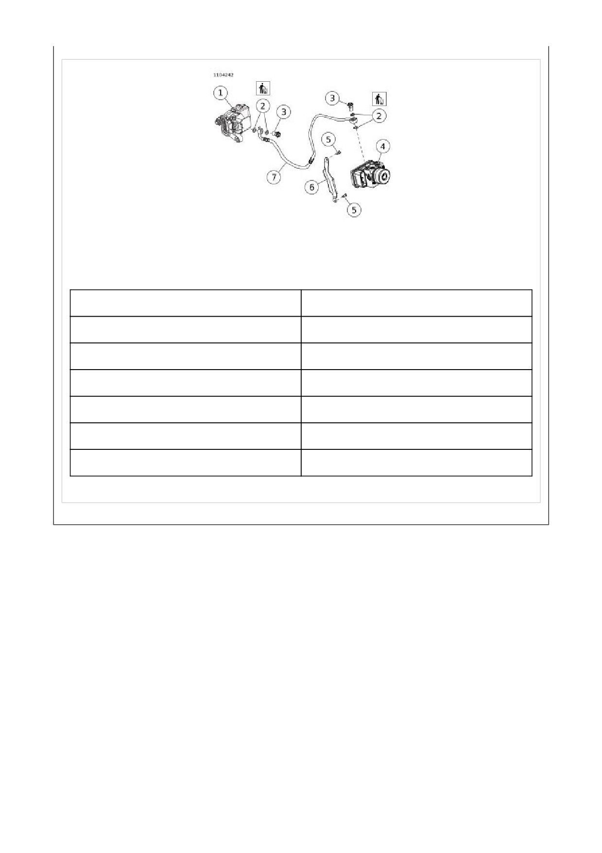
1
Rear caliper
2
Gasket (4)
3
Banjo bolt (2)
4
ABS Module
5
Screw (2)
6
Bracket
7
Brake line
Figure 2. Brake Line Routing
NOTE
The ABS (Anti-lock braking system) module consists of the HCU (Hydraulic control unit) and the ECU (Electronic
control unit). The two are not serviced separately.
1. Remove seat. See Remove.
2. Disconnect negative battery cable. See Main Fuse.
3. Remove right side cover. See Remove.
4. Drain fluid from system. See Drain.
5. Disconnect brake lines from ABS module. See Front
Brake Line: Non-ABS.
NOTICE
This device is sensitive to electrostatic discharge (ESD). To prevent damage to the device, always touch the
motorcycle frame or a grounded surface before handling. (00588c)
1. Remove ABS module.
a. See ABS Module. Disconnect ABS connector (4).
b. Remove cable straps (3).
c. Remove side cover mounting stud (2).
d. Remove screw (1).
e. See ABS Module Bracket. Remove ABS module (3)
with bracket.
f. Remove screws (2).
g. Remove bracket (1).