Harley Davidson Sportster Models 2009. Service Repair Manual - page 59
 

  Главная      Harley Davidson     Harley Davidson Sportster Models 2009. Service Repair Manual


Search            copyright infringement  


Content      ..     57      58      59      60     ..


Harley Davidson Sportster Models 2009. Service Repair Manual - page 59


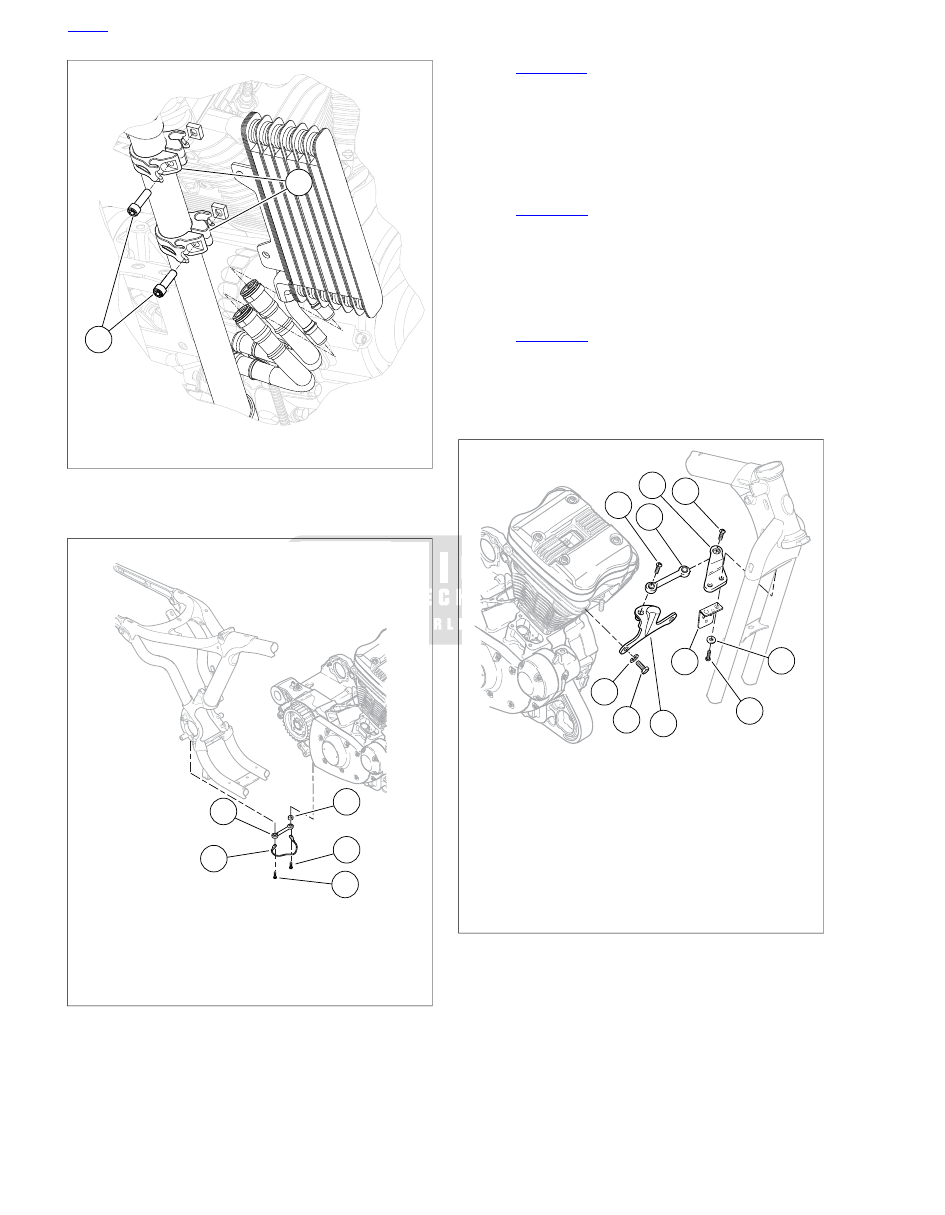
1

2

sm04953

1.

Fastener (2)

2.

Oil cooler mount (2)

Figure 3-22. Oil Cooler Mounts

5

4

3

2

1

sm03428

1.

Stabilizer link

2.

Grounding strap

3.

Screw

4.

Screw

5.

Spacer

Figure 3-23. Rear Stabilizer Link Assembly: Typical (XL

Model Shown)

31. See 

Figure 3-24

. Remove upper stabilizer link (2) and

upper frame bracket (3):

a.

Remove screw (4) securing stabilizer link to engine
bracket (1).

b.

Remove screws (5) and washers (8). Remove horn
bracket (9) and upper stabilizer link bracket (3) with
stabilizer link.

32. See 

Figure 3-25

. Remove lower stabilizer link (1) and

lower frame bracket (2) as an assembly:

a.

Remove screw (3) securing stabilizer link to engine
crankcase boss.

b.

Remove screws (4), washers (5) and lower frame
bracket with stabilizer link.

33. See 

Figure 3-26

. Remove fastener (1) and disconnect

shift linkage from transmission shift lever.

34. Remove fasteners (2) and remove rider left footrest and

mounting bracket assembly along with foot shift lever and
linkage.

4

7

9

5

8

6

1

2

3

4

sm03439

1.

Engine bracket

2.

Upper stabilizer link

3.

Upper frame bracket

4.

Screw

5.

Screw (2)

6.

Screw (2)

7.

Lock washer (2)

8.

Washer (2)

9.

Horn bracket (models with front mounted horn)

Figure 3-24. Upper Front Stabilizer Link Assembly:Typical

(XL Model Shown)

HOME

3-40  2009 Sportster Service: Engine

4

5

2

1

3

sm03440

1.

Lower stabilizer link

2.

Lower frame bracket

3.

Screw (2)

4.

Screw (2)

5.

Washer (2)

Figure 3-25. Lower Front Stabilizer Link Assembly:Typical

(XL Model Shown)

2

1

sm04961

1.

Fastener, shift linkage

2.

Fastener, footrest mount (2)

Figure 3-26. Left Footrest and Shift Linkage

35. With the aid of a FAT JACK (Part No. HD-45968), support

motorcycle on SHOP DOLLY (Part No. HD-45967).

36. See 

Figure 3-27

. Remove fasteners (13) and j-clip (14)

from each side of frame.

37. Loosen, but do not remove, two front isolator mounting

bracket screws (11) on left side of engine.

38. Loosen, but do not remove, two rear isolator mounting

bracket screws (3) on left side of engine.

39. Attach ENGINE HOOK (Part No. HD-46284) and engine

hoist. Carefully raise engine enough to relieve pressure
from mounting bolts.

40. Remove front engine mount bolt (10) and nut (12).

41. Remove two screws (11) and front isolator mount (9).

42. Remove two rear engine mount/rear fork pivot bolts (1).

Pull rear fork back until fork pivot bosses clear the frame.

43. Remove oil tank vent hose from oil tank. See 

3.27 OIL

TANK

.

44. Remove two screws (3) and rear isolator mounting bracket

(2) from frame.

HOME

2009 Sportster Service: Engine  3-41

1

1

2

3

7

6

5

4

8

8

9

10

11

12

14

13

7

sm04963

11.

6.

1.

Screw (2)

Screw (3)

Bolt (2)

2.

12.

7.

Rear isolator mount

Nut

Rear isolator (2)

8.

3.

13.

Front isolator (2)

Screw (2)

Screw

14.

9.

4.

J-clip (2)

Front isolator mount

Rear fork pivot shaft

5.

10.

Rear pivot lockplate

Front mount bolt

Figure 3-27. Engine Mount/Isolator Components (typical)

45. Rotate backbone electrical caddy to the left to allow room

to lift the engine.

46. Lift engine as necessary and swing assembly out from left

side of chassis, rear of engine first. Remove engine from
chassis.

HOME

3-42  2009 Sportster Service: Engine

3.13

INSTALLING ENGINE IN CHASSIS

GENERAL

When installing the engine in the motorcycle, follow the step-
by-step procedure below. It is important to follow the procedure
as outlined, particularly in the areas of stabilizer link and engine
mount assembly.

PROCEDURE: XL MODELS

TOOL NAME

PART NUMBER

SHOP DOLLY

HD-45967

FAT JACK

HD-45968

ENGINE HOOK

HD-46284

1.

See 

Figure 3-18

. Make sure pivot shaft (4) and rear pivot

lockplate (5) are mounted on engine mounting boss at
rear of engine. Position right rear isolator (7) on pivot shaft
on rear of engine. Do not install left rear isolator at this
time.

2.

Position right front isolator (8) on front of engine. Do not
install left front isolator at this time.

3.

Attach ENGINE HOOK (Part No. HD-46284) and engine
hoist to engine.

4.

Lift engine and swing assembly into chassis from left side.
Swing front of engine in first.

5.

Install left rear isolator (7) over pivot shaft (4). Install rear
isolator mount (2) over left rear isolator and attach to frame
with two screws (3). Do not tighten screws at this time.

6.

Raise or lower engine until right front isolator lines up with
mounting hole in frame.

7.

Install left front isolator (8) and front isolator mount (9) to
left side of frame with two screws (11). Do not tighten
screws at this time.

8.

Insert front engine mount bolt (10) from left side, through
isolators and crankcase boss. Place nut (12) on bolt but
do not tighten at this time.

9.

Tighten two screws (11) securing front isolator mount (9)
to 25-35 ft-lbs (33.9-47.5 Nm).

10. Tighten two screws (3) securing rear isolator mount (2) to

25-35 ft-lbs (33.9-47.5 Nm).

11. Using new hose clamp, install oil tank vent hose at oil

tank. See 

3.27 OIL TANK

.

12. Swing rear fork into position and install rear fork

pivot/engine mount bolts (1). Tighten to 60-70 ft-lbs (81.4-
95.0 Nm).

13. Tighten front engine mount bolt (10) and nut (12) to 60-70

ft-lbs (81.4-95.0 Nm).

14. Remove ENGINE HOOK (Part No. HD-46284).

15. With the aid of a FAT JACK (Part No. HD-45968), remove

motorcycle from SHOP DOLLY (Part No. HD-45967).

16. Carefully move rear stop lamp switch and brake lines into

place and secure switch assembly to battery tray with bolt.
Tighten to 72-120 in-lbs (8.1-13.6 Nm). Secure flexible

brake hose to battery tray with p-clamp and screw. Tighten
to 30-40 in-lbs (3.4-4.5 Nm). Plug rear stop lamp switch
connectors [121] into rear stop lamp switch. See

6.27 REAR STOP LAMP SWITCH

.

17. Install rear brake master cylinder remote reservoir. Secure

with screw with captive washer. Tighten to 20-25 in-lbs
(2.3-2.8 Nm). Install reservoir cover. See 

2.15 REAR

BRAKE MASTER CYLINDER RESERVOIR

.

18. Models equipped with passenger foot rests: Install left

passenger footrest assembly. Tighten mounting screws
to 45-50 ft-lbs (61-68 Nm). See 

2.43 PASSENGER

FOOTRESTS

.

19. Install shift lever and rider left footrest and mounting

bracket assembly:

a.

Models equipped with mid-mount foot controls:
see 

2.40 RIDER FOOT CONTROLS: XL MODELS

EQUIPPED WITH MID-MOUNT CONTROLS

.

b.

Models equipped with forward foot controls: see

2.41 RIDER FOOT CONTROLS: XL MODELS
EQUIPPED WITH FORWARD CONTROLS

.

20. See 

Figure 3-17

. Install lower front stabilizer link and frame

bracket:

a.

Install lower frame bracket (2) with stabilizer link (1),
and secure with screws (4) and washers (5). Tighten
screws to 25-35 ft-lbs (33.9-47.5 Nm).

b.

Install screw (3) securing stabilizer link to engine
crankcase boss. Tighten screw to 25-35 ft-lbs (33.9-
47.5 Nm).

21. See 

Figure 3-16

. Install upper stabilizer link (2) and upper

frame bracket (3):

a.

Install upper frame bracket with stabilizer link, horn
bracket (9) (models with front mounted horn), screws
(5) and washers (8). Tighten screws to 25-35 ft-lbs
(33.9-47.5 Nm).

b.

Install screw (4) securing stabilizer link to engine
bracket (1). Tighten screw to 25-35 ft-lbs (33.9-47.5
Nm).

22. See 

Figure 3-15

. Install spacer (5), rear stabilizer link (1),

grounding strap (2) and screws (3, 4). Tighten screws to
25-35 ft-lbs (33.9-47.5 Nm).

23. California models: install EVAP canister and hoses. See

4.21 EVAPORATIVE EMISSIONS CONTROL (CA
MODELS)

.

24. Install induction module and intake manifold. See

4.10 INDUCTION MODULE: XL MODELS

.

HOME

2009 Sportster Service: Engine  3-43

25. Position left and right wire harness caddies on either side

of frame backbone. Plug in the following connectors, loc-
ated in the caddies:

a.

Instruments connector [20].

b.

Headlamp connector [38].

c.

Right hand control connector (black) [22].

d.

Left hand control connector (gray) [24].

e.

Front turn signal connector [31].

26. Mount caddies together. Make sure tabs on caddies

engage each other and frame backbone bracket. Secure
with screw. See 

6.32 MAIN WIRING HARNESS

.

27. Position ignition coil and bracket on frame behind steering

head. Be certain all wiring harnesses from front end of
motorcycle, as well as right wire harness caddy mounting
boss and throttle cables are positioned properly between
coil bracket uprights.

28. Plug ignition coil harness connector [83] into coil. See

6.19 IGNITION COIL

. Mount ignition switch to coil bracket

with screw. Tighten screw to 34-45 in-lbs (4.0-5.1 Nm).
Secure right wire harness caddy to coil bracket with new
push-in fastener.

29. Connect clutch cable to clutch lever on left handlebar.

Attach clutch cable (along with wiring harness and front
O2 sensor harness) to frame front left downtube with cable
clips. Adjust clutch. See 

2.31 CLUTCH CONTROL

.

30. Plug the following electrical connectors into the engine:

a.

Engine Temperature (ET) sensor connector [90].
Secure sensor harness to H-bracket with barbed cable
strap. To avoid damage to sensor when vehicle is in
operation, position cable strap on harness so there
is a loop in harness between sensor and H-bracket.
Press barbed prong of cable strap into hole in boss
in H-bracket. See 

4.9 ENGINE TEMPERATURE (ET)

SENSOR

.

b.

Starter relay wire (GN) at starter motor. See

6.13 STARTER

.

c.

Vehicle speed sensor (VSS) connector [65]. See

6.30 VEHICLE SPEED SENSOR (VSS)

.

d.

Neutral indicator switch connector [136]. See

6.31 NEUTRAL INDICATOR SWITCH

.

e.

Alternator AC connector [46]. See 

6.3 VOLTAGE

REGULATOR

.

f.

Crank position (CKP) sensor connector [79]. See

6.28 CRANK POSITION SENSOR (CKP)

.

g.

Oil pressure switch connector [120]. See 

6.36 OIL

PRESSURE SWITCH

.

h.

Spark plug wires.

i.

Ground wire at powertrain ground stud on crankcase.

31. See 

4.10 INDUCTION MODULE: XL MODELS

 and plug

the following connectors into the induction module:

a.

Throttle position (TP) sensor connector [88].

b.

Idle air control (IAC) connector [87].

c.

Temperature/manifold absolute pressure (TMAP)
sensor connector [80].

d.

Fuel injector connectors [84], [85].

32. Models with front mounted horn: install horn. See

6.37 HORN

.

33. Models with side mounted horn: See 

Figure 3-14

. Install

cylinder head bracket (1) with horn (4) onto cylinder heads
as a unit. Secure with two screws (3) and washers (2).
Tighten screws to 17-24 ft-lbs (23.1-32.6 Nm). Plug wiring
harness connectors into horn.

34. Install air cleaner backing plate, air filter and air cleaner

cover. See 

4.4 AIR CLEANER: XL MODELS

. California

models: install EVAP purge hose on induction module.
See 

4.21 EVAPORATIVE EMISSIONS CONTROL (CA

MODELS)

.

When servicing the fuel system, do not smoke or allow
open flame or sparks in the vicinity. Gasoline is extremely
flammable and highly explosive, which could result in
death or serious injury. (00330a)

35. Install fuel tank. Tighten screws to 15-20 ft-lbs (20.4-27.1

Nm). Attach quick-connect fitting on fuel line to fuel tank
fitting. Gently tug on quick-connect fitting to make sure it
is securely locked in place. See 

4.6 FUEL TANK: XL

MODELS

.

36. Feed oil drain hose down through drain hose sleeve in

rear of engine crankcase. Using new hose clamps, install
oil tank feed, drain and return hoses onto oil tank. Install
drain plug in end of drain hose and secure with worm drive
clamp. Tighten clamp securely. See 

3.27 OIL TANK

.

37. Install exhaust system interconnect. See 

4.15 EXHAUST

SYSTEM: XL MODELS

.

38. Install transmission sprocket. See 

5.16 TRANSMISSION

SPROCKET

.

39. Install rear drive belt and hand-tighten rear axle. Final belt

adjustment will be performed later. See 

5.7 DRIVE BELT

.

40. Install sprocket cover. Secure with two screws. Note that

long screw goes in top hole, short screw in bottom hole.
Do not tighten screws at this time.

41. Install exhaust pipe clamp bracket, washer and screw to

sprocket cover. Tighten to 30-33 ft-lbs (40.7-44.8 Nm).
Now tighten other two sprocket cover screws to 80-120
in-lbs (9.0-13.6 Nm).

HOME

3-44  2009 Sportster Service: Engine

42. Install right front footrest assembly and rear brake linkage.

a.

Models equipped with mid-mount foot controls:
see 

2.40 RIDER FOOT CONTROLS: XL MODELS

EQUIPPED WITH MID-MOUNT CONTROLS

.

b.

Models equipped with forward foot controls: see

2.41 RIDER FOOT CONTROLS: XL MODELS
EQUIPPED WITH FORWARD CONTROLS

.

43. Install exhaust pipes and mufflers. Plug in O2 sensor

connectors [137], [138]. Make sure rear O2 sensor harness
is routed toward left side of motorcycle before looping back
to harness connector so that harness does not contact
exhaust pipe or port. See 

4.15 EXHAUST SYSTEM: XL

MODELS

.

44. Fill oil tank. See 

1.6 ENGINE OIL AND FILTER, Changing

Oil and Filter

.

45. Fill primary chaincase/transmission with transmission

lubricant. See 

1.14 TRANSMISSION LUBRICANT

.

46. Adjust belt tension and rear wheel alignment. Tighten rear

axle nut to 95-105 ft-lbs (129-142 Nm). Install new e-clip.
See 

1.16 REAR BELT DEFLECTION

.

Connect positive (+) battery cable first. If positive (+) cable
should contact ground with negative (-) cable connected,
the resulting sparks can cause a battery explosion, which
could result in death or serious injury. (00068a)

47. Connect positive (+) battery cables to battery. Connect

negative (-) battery cable to ground point on engine
crankcase. See 

1.17 BATTERY MAINTENANCE

.

48. Install left side cover. See 

2.20 LEFT SIDE COVER

.

After installing seat, pull upward on seat to be sure it is
locked in position. While riding, a loose seat can shift
causing loss of control, which could result in death or
serious injury. (00070b)

49. Install seat.

PROCEDURE: XR MODELS

TOOL NAME

PART NUMBER

SHOP DOLLY

HD-45967

FAT JACK

HD-45968

ENGINE HOOK

HD-46284

1.

See 

Figure 3-27

. Make sure pivot shaft (4) and rear pivot

lockplate (5) are mounted on engine mounting boss at
rear of engine. Position right rear isolator (7) on pivot shaft
on rear of engine. Do not install left rear isolator at this
time.

2.

Position right front isolator (8) on front of engine. Do not
install left front isolator at this time.

3.

Attach ENGINE HOOK (Part No. HD-46284) and engine
hoist to engine.

4.

Lift engine and swing assembly into chassis from left side.
Swing front of engine in first.

5.

Install left rear isolator (7) over pivot shaft (4). Install rear
isolator mount (2) over left rear isolator and attach to frame
with two screws (3). Do not tighten screws at this time.

6.

Raise or lower engine until right front isolator lines up with
mounting hole in frame.

7.

Install left front isolator (8) and front isolator mount (9) to
left side of frame with two screws (11). Do not tighten
screws at this time.

8.

Insert front engine mount bolt (10) from left side, through
isolators and crankcase boss. Place nut (12) on bolt but
do not tighten at this time.

9.

Tighten two screws (11) securing front isolator mount (9)
to 25-35 ft-lbs (33.9-47.5 Nm).

10. Tighten two screws (3) securing rear isolator mount (2) to

25-35 ft-lbs (33.9-47.5 Nm).

11. Using new hose clamp, install oil tank vent hose at oil

tank. See 

3.27 OIL TANK

.

12. Swing rear fork into position and install rear fork

pivot/engine mount bolts (1). Tighten to 60-70 ft-lbs (81.4-
95.0 Nm).

13. Tighten front engine mount bolt (10) and nut (12) to 60-70

ft-lbs (81.4-95.0 Nm).

14. Install j-clip (14) to each side of frame. Tighten fasteners

(13) to 45-50 ft-lbs (61.0-67.8 Nm).

15. Remove ENGINE HOOK (Part No. HD-46284).

16. With the aid of a FAT JACK (Part No. HD-45968), remove

motorcycle from SHOP DOLLY (Part No. HD-45967).

17. See 

Figure 3-25

. Install lower front stabilizer link and frame

bracket:

a.

Install lower frame bracket (2) with stabilizer link (1),
and secure with screws (4) and washers (5). Tighten
screws to 25-35 ft-lbs (33.9-47.5 Nm).

b.

Install screw (3) securing stabilizer link to engine
crankcase boss. Tighten screw to 25-35 ft-lbs (33.9-
47.5 Nm).

18. See 

Figure 3-24

. Install upper stabilizer link (2) and upper

frame bracket (3):

a.

Install upper frame bracket with stabilizer link, horn
bracket (9) (models with front mounted horn), screws
(5) and washers (8). Tighten screws to 25-35 ft-lbs
(33.9-47.5 Nm).

b.

Install screw (4) securing stabilizer link to engine
bracket (1). Tighten screw to 25-35 ft-lbs (33.9-47.5
Nm).

19. See 

Figure 3-23

. Install spacer (5), rear stabilizer link (1),

grounding strap (2) and screws (3, 4). Tighten screws to
25-35 ft-lbs (33.9-47.5 Nm).

20. See 

Figure 3-26

. Install shift lever and rider left footrest

and mounting bracket assembly. Tighten fasteners (2) to
45-50 ft-lb  (61.0-67.8 Nm)

HOME

2009 Sportster Service: Engine  3-45

21. Connect shift linkage to transmission shift lever. Tighten

fastener (1) to  10-15 ft-lbs  (13.6-20.3 Nm).

22. Install induction module and intake manifold. See

4.11 INDUCTION MODULE: XR MODELS

.

23. Rotate backbone wire harness caddy down into place.

24. See 

6.19 IGNITION COIL

. Position ignition coil and bracket

on backbone caddy behind steering head. Be certain all
wiring harnesses from front end of motorcycle, as well as
right wire harness caddy mounting boss and throttle cables
are positioned properly between coil bracket uprights.

25. Plug ignition coil harness connector [83] into coil. Mount

ignition switch to coil bracket with screw. Tighten screw
to 34-45 in-lbs (4.0-5.1 Nm). Secure right wire harness
caddy to coil bracket with new push-in fastener.

26. Connect clutch cable to clutch lever on left handlebar and

secure to lower oil cooler mount. Attach clutch cable (along
with wiring harness and front O2 sensor harness) to frame
front left downtube with cable clips. Adjust clutch. See

2.31 CLUTCH CONTROL

.

27. See 

Figure 3-22

. Install the oil cooler to the frame mounts.

Tighten fasteners (1) to 36-60 in-lbs (4.1-6.8 Nm)

28. Plug the following electrical connectors into the engine:

a.

Engine Temperature (ET) sensor connector [90].
Secure sensor harness to H-bracket with barbed cable
strap. To avoid damage to sensor when vehicle is in
operation, position cable strap on harness so there
is a loop in harness between sensor and H-bracket.
Press barbed prong of cable strap into hole in boss
in H-bracket. See 

4.9 ENGINE TEMPERATURE (ET)

SENSOR

.

b.

Starter relay wire (GN) at starter motor. See

6.13 STARTER

.

c.

Vehicle speed sensor (VSS) connector [65]. See

6.30 VEHICLE SPEED SENSOR (VSS)

.

d.

Neutral indicator switch connector [136]. See

6.31 NEUTRAL INDICATOR SWITCH

.

e.

Alternator AC connector [46]. Secure to right down-
tube with a tie strap. See 

6.3 VOLTAGE REGU-

LATOR

.

f.

Connect voltage regulator DC connector [77] and
secure to frame cross member with tie strap. See

6.3 VOLTAGE REGULATOR

.

g.

Crank position (CKP) sensor connector [79]. See

6.28 CRANK POSITION SENSOR (CKP)

.

h.

Oil pressure switch connector [120]. See 

6.36 OIL

PRESSURE SWITCH

.

i.

Spark plug wires.

j.

Ground wire at powertrain ground stud on crankcase.

29. See 

4.11 INDUCTION MODULE: XR MODELS

 and plug

the following connectors into the induction module:

a.

Throttle Position (TP) sensor connector [88].

b.

Idle Air Control (IAC) connector [87].

c.

Temperature/Manifold absolute pressure (TMAP)
sensor connector [80].

d.

Fuel injector connectors [84], [85].

30. Install and connect jiffy stand sensor. See 

6.34 JIFFY

STAND SWITCH: INTERNATIONAL MODELS

.

31. Install and connect horn. See 

6.37 HORN

.

32. See 

Figure 3-19

. Install induction module cover. Secure

TP sensor harness to cover during installation. Tighten
fasteners (2) to 20-24 ft-lbs  (27.1-32.5 Nm). Tighten
fastener (1) to  84-108 in-lbs (9.5-12.2 Nm). Tighten
fastener (3) to  84-108 in-lbs (9.5-12.2 Nm).

33. Install air cleaner assembly on induction module. Connect

breather hoses to rocker box fittings. See 

4.5 AIRBOX:

XR MODELS

. California models: install EVAP purge hose

on induction module. See 

4.21 EVAPORATIVE EMIS-

SIONS CONTROL (CA MODELS)

.

When servicing the fuel system, do not smoke or allow
open flame or sparks in the vicinity. Gasoline is extremely
flammable and highly explosive, which could result in
death or serious injury. (00330a)

34. Install fuel tank. Tighten screws to 15-20 ft-lbs (20.4-27.1

Nm). Attach quick-connect fitting on fuel line to fuel tank
fitting. Gently tug on quick-connect fitting to make sure it
is securely locked in place. See 

4.7 FUEL TANK: XR

MODELS

.

35. Secure air filter assembly to fuel tank with two screws.

36. Feed oil drain hose down through drain hose sleeve in

rear of engine crankcase. Using new hose clamps, install
oil tank feed, drain and return hoses onto oil tank. Install
drain plug in end of drain hose and secure with worm drive
clamp. Tighten clamp securely. See 

3.27 OIL TANK

.

37. See 

Figure 3-21

. Install right rider footrest assembly and

rear master cylinder assembly. Tighten fasteners (1) to
45-50 ft-lbs  (61.0-67.8 Nm).

38. See 

Figure 3-20

. Secure brake line and siren/canister

mount plate to frame and rear fork. Tighten fasteners (1)
to  17-22 ft-lbs  (23.0-29.8 Nm). Connect rear brake light
switch connectors.

39. Install these parts if present:

a.

California models: install EVAP canister and hoses.
See 

4.21 EVAPORATIVE EMISSIONS CONTROL

(CA MODELS)

.

b.

All other models: install siren if equipped. See

6.35 OPTIONAL SECURITY SIREN

.

40. If removed, install transmission sprocket. See

5.16 TRANSMISSION SPROCKET

.

HOME

3-46  2009 Sportster Service: Engine

41. Install rear drive belt and hand-tighten rear axle. Final belt

adjustment will be performed later. See 

5.7 DRIVE BELT

.

42. Secure right shock absorber to rear fork and tighten

fastener to  30-45 ft-lb  (40.7-61.0 Nm)

43. Install belt guard and debris deflector.

44. Install sprocket cover. Tighten rear (larger) screw to 30-

33 ft-lbs (40.7-44.8 Nm).Tighten forward and lower
(smaller) screws to 80-120 in-lbs (9.0-13.6 Nm).

45. Install exhaust pipes and mufflers. See 

4.16 EXHAUST

SYSTEM: XR MODELS

.

NOTE

It is important to route and secure the front O2 sensor harness
correctly to prevent premature harness failure. Closely follow
the procedure in 

4.14 OXYGEN SENSOR, Installation

.

46. Plug in O2 sensor connectors [137], [138]. Make sure each

O2 sensor harness is routed and secured correctly. See

4.14 OXYGEN SENSOR, Installation

.

47. Fill oil tank. See 

1.6 ENGINE OIL AND FILTER, Changing

Oil and Filter

.

48. Fill primary chaincase/transmission with transmission

lubricant. See 

1.14 TRANSMISSION LUBRICANT

.

49. Adjust belt tension and rear wheel alignment. Tighten rear

axle nut to 95-105 ft-lbs (129-142 Nm). Install new e-clip.
See 

1.16 REAR BELT DEFLECTION

.

Connect positive (+) battery cable first. If positive (+) cable
should contact ground with negative (-) cable connected,
the resulting sparks can cause a battery explosion, which
could result in death or serious injury. (00068a)

50. Connect positive (+) battery cables to battery. Connect

negative (-) battery cable to ground point on engine
crankcase. See 

1.17 BATTERY MAINTENANCE

.

51. Install left side cover. See 

2.20 LEFT SIDE COVER

.

After installing seat, pull upward on seat to be sure it is
locked in position. While riding, a loose seat can shift
causing loss of control, which could result in death or
serious injury. (00070b)

52. Install seat.

HOME

2009 Sportster Service: Engine  3-47

3.14

PRECISION COOLING SYSTEM: XR MODELS

GENERAL

TOOL NAME

PART NUMBER

OIL LINE REMOVER, 1/2 IN.

HD-46503

OIL LINE REMOVER, 3/8 IN.

HD-49096

See 

Figure 3-28

The oil lines used in the Precision Cooling

System incorporate flanged oil lines and quick connect fittings.
These fittings can be separated using either the OIL LINE
REMOVER, 1/2 IN. (Part No. HD-46503) or OIL LINE
REMOVER, 3/8 IN. (Part No. HD-49096) like that shown in

Figure 3-29

, depending on line diameter.

1.

See 

Figure 3-29

. Close the OIL LINE REMOVER over the

oil line. Match the notches in the tool flange to the U-bends
in the retainer clip.

2.

Rotate the tool to expand the spring clip.

3.

Use finger and thumb to hold the OIL LINE REMOVER
squarely against the fitting to keep the spring clip
expanded. Use only enough pressure to hold the tool
square. Excess pressure will prevent simultaneously
pulling the line and tool from the fitting.

4.

Pull the oil line and the tool from the fitting.

5.

To assemble, push the oil line squarely into quick connect
fitting to connect. Always apply a light film of clean engine
oil to the oil line to ease assembly and prevent damage
to the connector o-ring.

sm00207

Figure 3-28. Flanged Oil Line

sm00205

Figure 3-29. Oil Line Remover

RETURN OIL MANIFOLD

TOOL NAME

PART NUMBER

OIL LINE REMOVER, 3/8 IN.

HD-49096

Removal

1.

Disconnect and remove battery. See 

1.17 BATTERY

MAINTENANCE

.

2.

Remove exhaust system. See 

4.16 EXHAUST SYSTEM:

XR MODELS

.

3.

Drain oil tank. See 

1.6 ENGINE OIL AND FILTER

.

4.

Remove oil drain hose from sleeve in rear engine crank-
case.

5.

Remove battery positive (+) cable from starter motor. See

6.13 STARTER

.

6.

See 

Figure 3-31

. From right side of motorcycle, remove

fastener (1) securing oil manifold.

7.

See 

Figure 3-30

. Disconnect oil return hose (2) from oil

tank.

8.

Remove rear cylinder head oil line (1) from quick connect
fitting using OIL LINE REMOVER, 3/8 IN. (Part No. HD-
49096) while sliding return oil manifold back off from rigid
oil lines and remove assembly from engine.

HOME

3-48  2009 Sportster Service: Engine

1

2

sm04992

1.

Rear cylinder head oil line

2.

Return oil hose to tank

Figure 3-30. Rear Cylinder Oil Line

1

sm04993

1.

Fastener

Figure 3-31. Return Oil Manifold

Installation

NOTE

Used o-rings can leak. Always install new o-rings when per-
forming repairs.

1.

Install new o-rings in manifold assembly and apply a light
film of oil to them.

2.

Start return oil manifold on rigid lines and install rear cyl-
inder head oil line in quick connect fitting. Ensure it is
securely held by the retainer clip.

3.

See 

Figure 3-31

. Slide oil manifold onto rigid lines and

secure with screw (1). Tighten to 84-108 in-lbs (9.5-12.2
Nm).

4.

Connect oil return hose to oil tank. Secure with clamp.

5.

Install and connect oil tank drain hose. Install and secure
plug in drain hose.

6.

Connect battery positive (+) cable to starter. See

6.13 STARTER

.

7.

Install and connect battery. See 

1.17 BATTERY MAINTEN-

ANCE

.

8.

Fill oil tank with the appropriate oil. See 

1.6 ENGINE OIL

AND FILTER

.

CYLINDER HEAD OIL RETURN LINES

TOOL NAME

PART NUMBER

OIL LINE REMOVER, 3/8 IN.

HD-49096

Removal

1.

Remove return oil manifold. See 

3.14 PRECISION

COOLING SYSTEM: XR MODELS, Return Oil Manifold

.

2.

See 

Figure 3-32

. Remove fastener (1) and raise retainer

until alignment pin (2) is clear of bore in crankcase. Roll
retainer out from beneath rigid oil lines to remove.

3.

See 

Figure 3-33

. Remove nut (1) and washer.

4.

Separate front oil line (2) from cylinder head using OIL
LINE REMOVER, 3/8 IN. (Part No. HD-49096).

5.

Separate rear oil line (3) from cylinder head using OIL
LINE REMOVER, 3/8 IN. (Part No. HD-49096).

6.

If front oil line needs to be completely removed, remove
electric starter. See 

6.13 STARTER

.

7.

If necessary, remove quick connect fitting from cylinder
head.

1

2

sm04994

1.

Fastener

2.

Alignment pin (hidden)

Figure 3-32. Rigid Oil Line Retainer

HOME

2009 Sportster Service: Engine  3-49

1

3

2

sm04995

1.

Locknut

2.

Front oil line

3.

Rear oil line

Figure 3-33. Cylinder Head Oil Lines

Installation

NOTE

Used o-rings can leak. Always install new o-rings when per-
forming repairs.

1.

If removed from cylinder head, install quick connect fittings
with new o-rings. Tighten to  108-156 in-lbs (12.2-17.6
Nm).

2.

Install new internal o-rings in quick connect fittings.

3.

If removed, place front cylinder head oil line on engine
and install electric starter. See 

6.13 STARTER

.

NOTE

Apply a light film of oil to the end of the line before inserting it
into the fitting.

4.

See 

Figure 3-33

. Connect front oil line (2) to cylinder head.

Ensure it is securely held by the retainer clip.

5.

Secure front line to crankcase with locknut (1) and washer.
Tighten to  84-108 in-lbs (9.5-12.2 Nm).

6.

See 

Figure 3-32

. Roll retainer under rigid lines at rear of

crankcase and orient so alignment pin is in bore in case.
Ensure flanges on lines are on the manifold side of the
retainer. Secure with fastener (1) and tighten to  84-108
in-lbs (9.5-12.2 Nm)

7.

Install return oil manifold. See 

3.14 PRECISION COOLING

SYSTEM: XR MODELS, Return Oil Manifold

.

8.

See 

Figure 3-33

. Connect rear oil line (3) to cylinder head.

Ensure it is securely held by the retainer clip.

CYLINDER HEAD OIL FEED ASSEMBLY

Removal

1.

Disconnect the battery. See 

1.17 BATTERY MAINTEN-

ANCE

.

2.

Drain oil tank. See 

1.6 ENGINE OIL AND FILTER

.

3.

See 

Figure 3-34

. Disconnect flare nuts (1) from each cyl-

inder head.

4.

Pull oil feed hose connector (2) straight up to remove feed
hose assembly from check valve assembly (3).

5.

Remove two fasteners (4) and remove check valve
assembly (3).

6.

See 

Figure 3-35

. Carefully clamp assembly in vise and

remove plug fitting (7).

7.

Remove spring (5) and ball (4).

8.

If necessary, remove flare fittings from cylinder heads.

9.

Inspect components for wear or damage and replace as
necessary.

1

2

3

4

4

sm04998

1.

Feed oil line flare nut

2.

Feed oil line connector

3.

Check valve assembly

4.

Fastener (2)

Figure 3-34. Cylinder Head Oil Feed Assembly

3

2

1

4

5

6

7

sm04999

1.

Base o-ring

2.

Check valve housing

3.

O-ring

4.

Check ball

5.

Spring cartridge assembly

6.

O-ring

7.

Plug fitting

Figure 3-35. Check Valve Components

Installation

1.

See 

Figure 3-35

. Install ball (4) and spring (5) into housing

(2).

HOME

3-50  2009 Sportster Service: Engine

NOTE

Used o-rings can leak. Always install new o-rings when per-
forming repairs.

2.

Install new o-ring (6) on check valve plug fitting (7) and
install fitting. Tighten to  15-21 ft-lbs (20.3-28.5 Nm).

3.

Install new o-ring (3) in bore of housing.

4.

Install housing (2) with new base o-ring (1). Tighten
fasteners to 84-108 in-lbs (9.5-12.2 Nm).

5.

If removed, apply Loctite Threadlocker and Sealant (243)
to the flare fittings and install in cylinder heads with new
o-rings. Tighten fittings to 22-26 ft-lbs (29.8-35.3 Nm).

NOTE

Apply a light film of oil to the end of the line before inserting it
into the fitting.

6.

See 

Figure 3-34

. Push oil feed hose assembly straight

down to install. Connect oil line flare nuts (1) to cylinder
head flare fittings. Hold lines to prevent rotation and tighten
to 13-17 ft-lbs (17.6-23.0 Nm).

7.

Install and connect battery. See 

1.17 BATTERY MAINTEN-

ANCE

.

8.

Fill oil tank with the appropriate oil. See 

1.6 ENGINE OIL

AND FILTER

.

OIL PUMP LINES

TOOL NAME

PART NUMBER

OIL LINE REMOVER, 1/2 IN.

HD-46503

OIL LINE REMOVER, 3/8 IN.

HD-49096

Removal

1.

Remove return oil manifold. See 

3.14 PRECISION

COOLING SYSTEM: XR MODELS, Return Oil Manifold

.

2.

See 

Figure 3-36

. Remove fastener (1) and raise retainer

until alignment pin (2) is clear of bore in crankcase. Roll
retainer out from beneath rigid oil lines to remove.

3.

See 

Figure 3-37

. Remove return oil line (1) from gearcase

cover using OIL LINE REMOVER, 3/8 IN. (Part No. HD-
49096).

4.

If return oil line needs to be completely removed, remove
electric starter. See 

6.13 STARTER

.

5.

Remove feed oil line (2) from gearcase cover using OIL
LINE REMOVER, 1/2 IN. (Part No. HD-46503).

6.

Disconnect vent hose (3) from fitting on oil pump.

7.

See 

Figure 3-38

. Remove locknut (1) and washer. Remove

oil cooler line retainer (2) from lines.

8.

See 

Figure 3-37

. Release each oil cooler line (4, 5) from

bottom of gearcase cover using OIL LINE REMOVER, 1/2
IN. (Part No. HD-46503).

9.

If necessary, remove quick connect fittings.

1

2

sm04994

1.

Fastener

2.

Alignment pin (hidden)

Figure 3-36. Rigid Oil Line Retainer

2

1

3

5

4

sm04996

1.

Oil pump return line

2.

Oil Pump feed line

3.

Vent hose

4.

Oil cooler line, to cooler

5.

Oil cooler line, from cooler

Figure 3-37. Oil Pump Lines

1

2

sm04997

1.

Locknut

2.

Line retainer (partially hidden)

Figure 3-38. Oil Cooler Line Retainer

HOME

2009 Sportster Service: Engine  3-51

Installation

NOTE

Used o-rings can leak. Always install new o-rings when per-
forming repairs.

1.

If removed, install quick connect fittings with new o-rings.
Tighten to 108-156 in-lbs (12.2-17.6 Nm).

2.

Install new o-rings in quick connect fittings.

NOTE

Apply a light film of oil to the end of each line before inserting
it into the fitting.

3.

See 

Figure 3-37

. Connect oil cooler lines (4, 5) to lower

gearcase cover. Ensure each is securely held by the
retainer clip.

4.

See 

Figure 3-38

. Install oil cooler line retainer (2) and

tighten nut (1) securely.

5.

See 

Figure 3-37

. If removed, place return line (1) on

engine and install electric starter. See 

6.13 STARTER

.

6.

Connect vent (3), feed oil (2) and return oil (1) lines to oil
pump body and cam support. Ensure each is securely
held by the retainer clip.

7.

See 

Figure 3-36

. Roll retainer under rigid lines at rear of

crankcase and orient so alignment pin (2) is in bore in
case. Ensure flanges on lines are on the manifold side of
the retainer. Secure with screw (1) and tighten to 84-108
in-lbs (9.5-12.2 Nm).

8.

Install return oil manifold. See 

3.14 PRECISION COOLING

SYSTEM: XR MODELS, Return Oil Manifold

.

9.

Fill oil tank with the appropriate oil. See 

1.6 ENGINE OIL

AND FILTER

.

OIL COOLER

TOOL NAME

PART NUMBER

OIL LINE REMOVER, 1/2 IN.

HD-46503

Removal

1.

Disconnect the battery. See 

1.17 BATTERY MAINTEN-

ANCE

.

2.

Drain oil tank. See 

1.6 ENGINE OIL AND FILTER

.

3.

Using OIL LINE REMOVER, 1/2 IN. (Part No. HD-46503),
separate oil cooler lines from oil cooler.

4.

See 

Figure 3-39

. Remove fasteners (1) securing oil cooler

to frame brackets.

5.

Remove oil cooler from motorcycle.

6.

If necessary, remove oil cooler rigid lines from gearcase
cover. See 

3.14 PRECISION COOLING SYSTEM: XR

MODELS, Oil Pump Lines

.

1

2

sm04953

1.

Fastener (2)

2.

Oil cooler mount (2)

Figure 3-39. Oil Cooler Mounts

Installation

NOTE

Used o-rings can leak. Always install new o-rings when per-
forming repairs.

1.

Install new o-rings in quick connect fittings.

2.

If removed, install oil cooler rigid lines. See 

3.14 PRECI-

SION COOLING SYSTEM: XR MODELS, Oil Pump Lines

.

3.

See 

Figure 3-39

. Secure oil cooler to frame brackets.

Tighten fasteners (1) to 36-60 in-lbs (4.1-6.8 Nm).

NOTE

Apply a light film of oil to the end of the line before inserting it
into the fitting.

4.

Connect oil lines to oil cooler fittings. Ensure each is
securely held by the retainer clip.

5.

Fill the oil tank. See 

1.6 ENGINE OIL AND FILTER

.

6.

Connect the battery. See 

1.17 BATTERY MAINTENANCE

.

HOME

3-52  2009 Sportster Service: Engine

3.15

TOP END OVERHAUL: DISASSEMBLY

GENERAL

This section describes disassembling the top end of the engine,
from the cylinder deck up. To perform a complete top end
overhaul, follow all steps listed in this section. Then follow all
steps listed in the following sections, including inspection and
repair procedures:

3.21 CYLINDER HEAD

3.22 CYLINDER

AND PISTON

, and 

3.19 VALVE TAPPETS

.

NOTE

Dirt caked on cooling fins and other areas of engine can fall
into crankcase bore or stick to subassemblies as parts are
removed. Abrasive particles can damage machined surfaces
or plug oil passageways. Remove all dirt and particles before
disassembly to prevent component damage.

STRIPPING MOTORCYCLE FOR TOP END
REPAIR

When servicing the fuel system, do not smoke or allow
open flame or sparks in the vicinity. Gasoline is extremely
flammable and highly explosive, which could result in
death or serious injury. (00330a)

1.

Purge the fuel supply hose of high pressure gasoline.
Disconnect fuel supply hose from fuel pump module. See

4.6 FUEL TANK: XL MODELS

 or 

4.7 FUEL TANK: XR

MODELS

.

2.

Remove seat.

To prevent accidental vehicle start-up, which could cause
death or serious injury, remove main fuse before pro-
ceeding. (00251b)

3.

Unplug main fuse. See 

6.38 MAIN FUSE

.

4.

Unplug O2 sensor connectors [137], [138] and remove
exhaust pipes and mufflers. See 

4.15 EXHAUST SYSTEM:

XL MODELS

 or 

4.16 EXHAUST SYSTEM: XR MODELS

.

5.

Disconnect spark plug cables from spark plugs.

6.

Drain and remove fuel tank. See 

4.6 FUEL TANK: XL

MODELS

 or 

4.7 FUEL TANK: XR MODELS

.

7.

Models with side mounted horn: unplug wiring harness
connectors from horn. See 

Figure 3-14

. Remove two

screws (3) and washers (2). Remove cylinder head bracket
(1) and horn (4) from cylinder heads as an assembly.

1

3

2

4

sm01471

1.

Cylinder head bracket

2.

Washer (2)

3.

Screw (2)

4.

Horn assembly

Figure 3-40. Horn and Cylinder Head Bracket (Models With

Side Mounted Horn Only)

8.

Models with front mounted horn: unplug horn con-
nectors and remove horn from horn bracket. See

6.37 HORN

.

9.

Remove air cleaner assembly:

a.

XL models: remove cover, air filter and air cleaner
backing plate. See 

4.4 AIR CLEANER: XL MODELS

.

b.

California models: remove EVAP purge hose from
induction module. See 

4.21 EVAPORATIVE EMIS-

SIONS CONTROL (CA MODELS)

.

10. See 

4.10 INDUCTION MODULE: XL MODELS

 or

4.11 INDUCTION MODULE: XR MODELS

 and unplug the

following connectors from the induction module and
remove induction module:

a.

Fuel injector connectors [84], [85].

b.

Temperature/Manifold absolute pressure (TMAP)
sensor connector [80].

c.

Idle Air Control (IAC) connector [87].

d.

Throttle Position (TP) sensor connector [88].

11. Secure induction module assembly and throttle cables out

of the way.

HOME

2009 Sportster Service: Engine  3-53

12. See 

Figure 3-41

. Remove upper front stabilizer link and

frame bracket:

a.

Remove screw (4) securing stabilizer link (2) to engine
bracket (1).

b.

Remove screws (5) and washers (8). Remove horn
bracket (9) (models with front mounted horn) and
frame bracket (3) with stabilizer link.

4

3

2

4

7

6

1

9

5

8

sm01472

1.

Engine bracket

2.

Upper stabilizer link

3.

Upper frame bracket

4.

Screw

5.

Screw (2)

6.

Screw (2)

7.

Lock washer (2)

8.

Washer (2)

9.

Horn bracket (models with front mounted horn
only)

Figure 3-41. Upper Front Stabilizer Link Assembly (typical)

CYLINDER HEADS

Disassembling Rocker Covers

Prevent engine damage. Washers and fasteners used in
the engine are hardened parts. Do not use unhardened
parts. (00544b)

1.

Remove spark plugs.

2.

See 

Figure 3-42

. Remove four screws with captive

washers (1) and sealing washers (2). Remove outer rocker
cover (3) or (20). Discard sealing washers.

3.

Remove and discard gaskets (4, 5).

4.

Rotate crankshaft until both valves are closed on head
being removed.

HOME

3-54  2009 Sportster Service: Engine

3

1

2

1

2

8

18

16

21

17

6

7

19

15

14

13

10

20

9

10

11

4

5

5

4

24

22

23

12

sm01473

13.

1.

Bolt (4)

Screw w/ captive washer (4)

2.

14.

Sealing washer (4)

Screw (2)

15.

3.

Bolt (3)

Outer rocker cover: XL Models

4.

16.

Gasket

Gasket

17.

5.

Breather seal: XL Models

Gasket

6.

18.

Screw

Breather location: Front Cylinder: XL Models

19.

7.

Breather location: Rear Cylinder: XL Models

Breather assembly: XL Models

8.

20.

Inner rocker cover: XL Models

Outer rocker cover: XR Models

21.

9.

Breather hose fitting hole: XR Models

Rocker arm shaft (2)

10.

22.

Rocker arm bushing (4)

O-ring: XR Models

23.

11.

Breather filter and valve assembly: XR Models

Rocker arm

12.

24.

Rocker arm

Inner rocker cover: XR Models

Figure 3-42. Rocker Cover Assembly

HOME

2009 Sportster Service: Engine  3-55


Content      ..     57      58      59      60     ..