Harley Davidson Sportster Models 2009. Service Repair Manual - page 5
 

  Главная      Harley Davidson     Harley Davidson Sportster Models 2009. Service Repair Manual


Search            copyright infringement  


Content      ..     3      4      5      6     ..


Harley Davidson Sportster Models 2009. Service Repair Manual - page 5


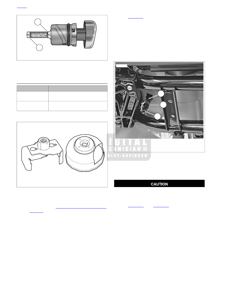
1

2

sm01413

1.

Upper mark (full)

2.

Lower mark (add qt.)

Figure 1-3. Oil Level Marks on Dipstick (typical; XL model

shown)

CHANGING OIL AND FILTER

TOOL NAME

PART NUMBER

HARLEY-DAVIDSON OIL FILTER
WRENCH

HD-42311

HARLEY-DAVIDSON OIL FILTER
WRENCH

HD-44067-A

General

sm01673

Figure 1-4. Oil Filter Wrenches

Completely drain oil tank of used oil at scheduled service
intervals as specified in 

1.4 MAINTENANCE SCHEDULE

.

Refer to 

Table 1-3

. Refill with fresh oil.

NOTES

If vehicle is driven extremely hard, used in competition, or
driven on dusty roads, change engine oil at shorter inter-
vals.

Always change oil filter when changing engine oil.

Draining Oil Tank

1.

Run engine until engine oil has reached normal operating
temperature.

NOTE

Oil will drain more quickly if filler cap/dipstick is removed from
oil tank.

2.

Remove oil filler cap/dipstick from oil tank.

3.

See 

Figure 1-5

. Place a suitable container directly under

the drain hose (1) at the bottom rear of the engine crank-
case. The container must be able to hold approximately
4.0 quarts (3.8 liters).

4.

Loosen worm drive clamp (2) and pull drain plug (3) from
end of drain hose. Completely drain engine oil from oil
tank. It is not necessary to drain engine crankcase.

5.

Replace drain plug into end of drain hose and tighten worm
drive clamp securely.

2

3

1

sm01684

1.

Oil tank drain hose

2.

Worm drive clamp

3.

Drain plug

Figure 1-5. Oil Tank Drain Hose (typical; XL model shown)

Removing Oil Filter

1.

Place a drain pan beneath front of engine crankcase.

Use Harley-Davidson oil filter wrench for filter removal.
This tool can prevent damage to crankshaft position
sensor and/or sensor cable. (00192b)

2.

See 

Figure 1-4

. See 

Figure 1-6

. Remove oil filter using

HARLEY-DAVIDSON OIL FILTER WRENCH (Part
No. HD-42311) or HARLEY-DAVIDSON OIL FILTER
WRENCH (Part No. HD-44067-A). Turn oil filter counter-
clockwise to remove from filter mount.

3.

Drain oil filter into drain pan. Discard oil filter.

4.

Clean any oil spills off crankcase and frame.

HOME

1-16  2009 Sportster Service: Maintenance

2

1

sm03917

1.

Oil filter mount

2.

Oil filter

Figure 1-6. Oil Filter: All Models (XL 1200C Shown)

Installing New Oil Filter

NOTE

Partially fill oil filter before installation to minimize the time
required for buildup of oil pressure when engine is first started.

1.

Pour about 4 fluid ounces (120 ml) of fresh, clean engine
oil into new oil filter. Allow time for oil to soak into filter
element.

2.

Wipe filter gasket contact surface of oil filter mount with a
clean cloth.

3.

See 

Figure 1-7

. Coat oil filter gasket with clean Harley-

Davidson 20W-50 engine oil.

NOTE

Do not use oil filter wrench to install new oil filter.

4.

Install new oil filter. Turn filter clockwise to install. Hand
tighten filter 1/2 to 3/4-turn after gasket contacts filter
mount surface.

Refilling Oil Tank

Do not overfill oil tank. Doing so can result in oil carryover
to the air cleaner leading to equipment damage and/or
equipment malfunction. (00190a)

1.

Refer to 

Table 1-2

. Always use the proper grade of oil for

the lowest expected air temperature before the next regu-
larly scheduled oil change. Pour 2.0 quarts (1.9 liters) of
oil into engine oil tank.

1

3

2

om00108

1.

Thin oil film ONLY

2.

Oil filter

3.

Mounting plate

Figure 1-7. Applying Thin Oil Film

Loosen clamp and pull plug from end of oil tank drain
hose. Allow a small amount of oil to flow from hose before
reinstalling drain plug. This removes air from the drain
hose and reduces the possibility of oil pump cavitation.
(00560b)

2.

Install filler cap onto oil tank as described on previous
page. Make sure cap is fully seated.

3.

Start engine. See 

Figure 1-8

. Verify that oil pressure signal

lamp turns off when engine speed is 1000 RPM or above.
Turn engine off.

4.

Check for oil leaks at oil filter and oil tank drain hose.
Check engine oil level. See 

1.6 ENGINE OIL AND FILTER,

Checking and Adding Oil

 earlier in this section.

sm01415

Figure 1-8. Oil Pressure Indicator Lamp

HOME

2009 Sportster Service: Maintenance  1-17

1.7

BRAKES

GENERAL

The front and rear brakes are fully hydraulic disc brake systems
that require little maintenance. The front brake master cylinder
is an integral part of the brake hand lever assembly on the right
handlebar. The rear brake master cylinder is located at the
rear of the motorcycle's frame, beneath the rear fork pivot point
and is actuated by the rear brake pedal via mechanical linkage.

Use denatured alcohol to clean brake system components.
Do not use mineral-based solvents (such as gasoline or
paint thinner), which will deteriorate rubber parts even
after assembly. Deterioration of these components can
cause brake failure, which could result in death or serious
injury. (00291a)

Direct contact of D.O.T. 4 brake fluid with eyes can cause
irritation. Avoid eye contact. In case of eye contact flush
with large amounts of water and get medical attention.
Swallowing large amounts of D.O.T. 4 brake fluid can cause
digestive discomfort. If swallowed, obtain medical atten-
tion. Use in well ventilated area. KEEP OUT OF REACH OF
CHILDREN. (00240a)

D.O.T. 4 brake fluid will damage painted and body panel
surfaces it comes in contact with. Always use caution and
protect surfaces from spills whenever brake work is per-
formed. Failure to comply can result in cosmetic damage.
(00239b)

NOTES

If D.O.T. 4 brake fluid contacts painted surfaces, IMMEDI-
ATELY flush area with clear water.

Cover handlebar switches with a shop towel before adding
brake fluid to front master cylinder reservoir. Spilling brake
fluid on handlebar switches may render them inoperative.

After repairing the brake system, test brakes at low speed.
If brakes are not operating properly, testing at high speeds
can cause loss of control, which could result in death or
serious injury. (00289a)

INSPECTION

Check the master cylinder reservoirs for proper fluid levels.
With the reservoir in a level position, add HARLEY-DAVIDSON
D.O.T. 4 BRAKE FLUID from a sealed container until the fluid
level is within approximately 1/4-inch (6.35 mm) below the top
edge of the reservoir (front brake) or reaches the upper fluid
level in the reservoir (rear brake).

Do not overfill the reservoir. See 

1.8 BLEEDING HYDRAULIC

BRAKE SYSTEM

 for procedures related to filling reservoirs.

Check brake pads and discs for wear. Replace brake pads if
friction material is worn to 0.04 in. (1.02 mm) or less. Minimum
brake disc thickness is stamped on side of disc. Replace any
brake disc that is worn beyond this limit. Maximum brake rotor
lateral runout and warpage is 0.008 in. (0.2 mm) when meas-
ured near the outside diameter.

For disc replacement procedures, see 

2.4 WHEELS

.

For XL Models brake master cylinder service, see:

2.10 FRONT BRAKE MASTER CYLINDER

 or 

2.13 REAR

BRAKE MASTER CYLINDER: XL MODELS

.

For XR Models brake master cylinder service, see:

2.10 FRONT BRAKE MASTER CYLINDER

 or 

2.14 REAR

BRAKE MASTER CYLINDER: XR MODELS

.

For XL Models brake caliper service, see:

2.11 FRONT

BRAKE CALIPER: XL MODELS

 or 

2.16 REAR BRAKE

CALIPER: XL MODELS

.

For XR Models brake caliper service, see:

2.12 FRONT

BRAKE CALIPER: XR MODELS

 or 

2.17 REAR BRAKE

CALIPER: XR MODELS

.

For brake line replacement procedures, see 

2.18 BRAKE

LINES

.

TROUBLESHOOTING

Use the following troubleshooting guide to help in determining
probable causes of poor brake operation.

HOME

1-18  2009 Sportster Service: Maintenance

Table 1-7. Troubleshooting Brakes

REMEDY

CHECK FOR

CONDITION

Bleed brake system.

Fill master cylinder reservoir with
approved brake fluid. Bleed brake
system.

Air in system.

Master cylinder reservoir low on fluid.

Excessive lever or pedal travel or spongy
feel.

Replace brake pads.

Tighten bolts.

Replace brake disc.

Worn brake pads.

Loose mounting bolts.

Warped brake disc.

Chattering sound when brake is applied.

Fill master cylinder reservoir with
approved brake fluid, and bleed brake
system.

Rebuild master cylinder.

Low fluid level.

Piston cup not functioning.

Ineffective brake - lever or pedal travels
to limit.

Replace brake disc.

Replace brake pads.

Distorted or glazed brake disc.

Distorted, glazed or contaminated
brake pads.

Ineffective brake - lever or pedal travel
normal.

Inspect master cylinder.

Cup in master cylinder not uncovering
relief port.

Brake pads drag on disc - will not retract.

HOME

2009 Sportster Service: Maintenance  1-19

NOTE

Since some material is typically removed from the cylinder
head valve guide bore when the valve guide is pressed out, it
is common to go to the larger size for the proper interference
fit.

2.

Measure cylinder head bore and outside diameter of
replacement valve guide to verify correct interference fit.

NOTE

Cylinder head support stand keeps valve guide and valve seat
perpendicular. If perpendicularity is not achieved, cylinder head
valve guide bore will be damaged during the press procedure.

3.

Prepare cylinder head for valve guide replacement.

a.

See 

Figure 3-123

. Insert sleeve of intake (4 or 6) or

exhaust (5 or 7) seat adapter into tube at top of cyl-
inder head support stand (3). Position cylinder head
so that valve seat is centered on seat adapter.

b.

Apply Vaseline to lightly lubricate external surfaces
of valve guide. Spread lubricant so that thin film
covers entire surface area.

c.

At top of cylinder head, start valve guide into bore.

d.

Place installer sleeve (2) over valve guide and then
insert VALVE GUIDE REMOVER/INSTALLER (1)
into installer sleeve.

e.

See 

Figure 3-125

. Center VALVE GUIDE

REMOVER/INSTALLER (1) under ram of press and
apply pressure only until valve guide is started in bore
and then back off ram slightly to allow valve guide to
center itself.

NOTE

Always back off ram to allow the valve guide to find center.
Pressing valve guide into cylinder head in one stroke can
bend remover/installer, break valve guide, distort cylinder
head casting and/or damage cylinder head valve guide
bore.

f.

Verify that cylinder head support stand (3) and VALVE
GUIDE REMOVER/INSTALLER are square. Center
VALVE GUIDE REMOVER/INSTALLER under ram
and press valve guide further into bore, then back off
ram again to allow valve guide to find center.

g.

Repeat previous step and then apply pressure to
VALVE GUIDE REMOVER/INSTALLER until installer
sleeve (2) contacts machined area of cylinder head
surrounding valve guide.

h.

XR models: Install new lock ring into valve guide
groove. Make sure that lock ring is square and fully
seated in the groove.

1

2

3

sm01524

1.

Valve guide remover/installer

2.

Installer sleeve

3.

Cylinder head support stand

Figure 3-125. Installing Shoulderless Valve Guide

4.

Secure cylinder head for service.

a.

See 

Figure 3-126

Thread 12 mm end of CYLINDER

HEAD HOLDING FIXTURE (Part No. HD-39786) into
cylinder head spark plug hole.

b.

Clamp tool in vise at a 45 degree angle or one that
offers a comfortable working position.

NOTE

Valve guides must be reamed to within 0.0005-0.0001 in.
(0.013-0.0025 mm) of finished size.

HOME

3-106  2009 Sportster Service: Engine

3

1

2

sm01525

1.

T-handle

2.

Valve guide reamer

3.

Cylinder head holding fixture

Figure 3-126. Reaming Valve Guide Bore

NOTES

Avoid damage to valve guide bore. Never back reamer
out of valve guide.

For best results, do not push on reamer or apply pressure
to the reamer handle. While excessive pressure results in
a rough cut, bore will be tapered if pressure is not centrally
applied.

5.

Obtain the VALVE GUIDE REAMER (Part No. B-45523)
(2) and REAMER T-HANDLE (Part No. HD-39847) (1).

a.

Install T-handle on reamer.

b.

Start bit of reamer into bore at top of cylinder head.

c.

Placing thumb on drive socket of REAMER T-
HANDLE, apply slight pressure on reamer while
rotating in a clockwise direction.

d.

Continue rotating REAMER T-HANDLE until entire
bit has passed through valve guide bore and shank
of reamer rotates freely.

e.

Remove T-handle from reamer. Carefully pulling on
bit, draw shaft of reamer out combustion chamber
side of valve guide.

NOTE

Abrasive particles can damage machined surfaces and plug
oil passageways possibly resulting in engine failure.

Compressed air can pierce the skin and flying debris from
compressed air could cause serious eye injury. Wear
safety glasses when working with compressed air. Never
use your hand to check for air leaks or to determine air
flow rates. (00061a)

6.

Direct compressed air into the valve guide bore to remove
any metal shavings or debris.

7.

See 

Figure 3-127

. Clean valve guide bore with the VALVE

GUIDE CLEANING BRUSH (Part No. HD-34751) (1).

8.

See 

Figure 3-128

. Obtain the VALVE GUIDE HONE (Part

No. B-45525) and REAMER LUBRICANT (Part No. HD-
39964).

a.

Install hone in a high speed electric drill.

b.

Apply REAMER LUBRICANT to finishing stones of
hone and valve guide bore.

c.

Start finishing stones of hone into bore.

d.

Activating the drill, move the entire length of the fin-
ishing stone arrangement forward and backward
through the bore for 10 to 12 complete strokes. Work
for a crosshatch pattern of approximately 60°.

NOTE

The hone is not intended for the removal of material.

sm01526

1

2

1.

Valve guide brush

2.

Cylinder head holding fixture

Figure 3-127. Scrubbing Valve Guide Bore

HOME

2009 Sportster Service: Engine  3-107

1

2

sm01527

1.

Valve guide hone

2.

Cylinder head holding fixture

Figure 3-128. Honing Valve Guide Bore

NOTE

Abrasive particles can damage machined surfaces and plug
oil passageways possibly resulting in engine failure.

Compressed air can pierce the skin and flying debris from
compressed air could cause serious eye injury. Wear
safety glasses when working with compressed air. Never
use your hand to check for air leaks or to determine air
flow rates. (00061a)

9.

Direct low pressure compressed air into the valve guide
bore to remove any debris.

10. See 

Figure 3-127

. Clean bore with the VALVE GUIDE

CLEANING BRUSH (1).

NOTE

Always verify valve stem to valve guide clearance after honing,
since a worn reamer may cut the bore undersize.

11. Check valve stem to valve guide clearance.

a.

Measure the inside diameter of the valve guide with
an inside ball micrometer.

b.

Measure the outside diameter of the valve stem with
an outside micrometer.

c.

Refer to 

Table 3-32

. If the clearance between valve

stem and valve guide is not within the limits shown,
the low end being preferable, then the valve stem
may be excessively worn or the valve guide bore
undercut.

12. Clean cylinder head assembly again.

a.

Using cleaning solvent, thoroughly clean cylinder head
and valve guide bore.

b.

Scrub valve guide bore with the VALVE GUIDE
CLEANING BRUSH. For best results, use a thin
engine oil and clean valve guide bore with the type
of swabs or patches found in gun cleaning kits.

c.

Continue to wipe bore until clean cloth shows no
evidence of dirt or debris. Follow up with a thorough
wash in hot soapy water.

Compressed air can pierce the skin and flying debris from
compressed air could cause serious eye injury. Wear
safety glasses when working with compressed air. Never
use your hand to check for air leaks or to determine air
flow rates. (00061a)

13. Blow parts dry with low pressure compressed air.

REFACING VALVE SEATS

TOOL NAME

PART NUMBER

CUTTER PILOT

B-35758-52A

VALVE GUIDE CLEANING BRUSH

HD-34751

NEWAY VALVE SEAT CUTTER SET

HD-35758-C

CYLINDER HEAD HOLDING FIXTURE

HD-39786

NOTES

Check that valve stem to valve guide clearance is correct
before refacing. Refer to 

Table 3-32

. If new valve guides

must be installed, see 

3.21 CYLINDER HEAD, Replacing

Valve Guides

 and complete that task before refacing valve

seats.

This procedure is not based on the lapping of valves. The
end result is an interference fit between the 45° valve face
and the valve seat which will be 46°.

1.

Secure cylinder head for servicing.

a.

Thread 12 mm end of CYLINDER HEAD HOLDING
FIXTURE (Part No. HD-39786) into cylinder head
spark plug hole.

b.

Clamp fixture in vise and further tighten cylinder head
onto the fixture to prevent any movement during
operation.

c.

Place cylinder head at a 45° angle or one that offers
a comfortable working position.

2.

In order to determine the correct location of the 46° valve
seat in the head, measure the width of the valve to be
used and subtract 0.080 in. (2.032 mm) from that number.

3.

Set your dial caliper to the lesser measurement and lock
it down for quick reference. This is the location of your
valve seat.

4.

Use a permanent magic marker to highlight the valve seat
area that is going to be cut. Be sure to highlight all three
angles. Allow marker to dry before proceeding.

HOME

3-108  2009 Sportster Service: Engine


Content      ..     3      4      5      6     ..