Harley Davidson 2005 touring models. Service repair manual - page 65
HOME
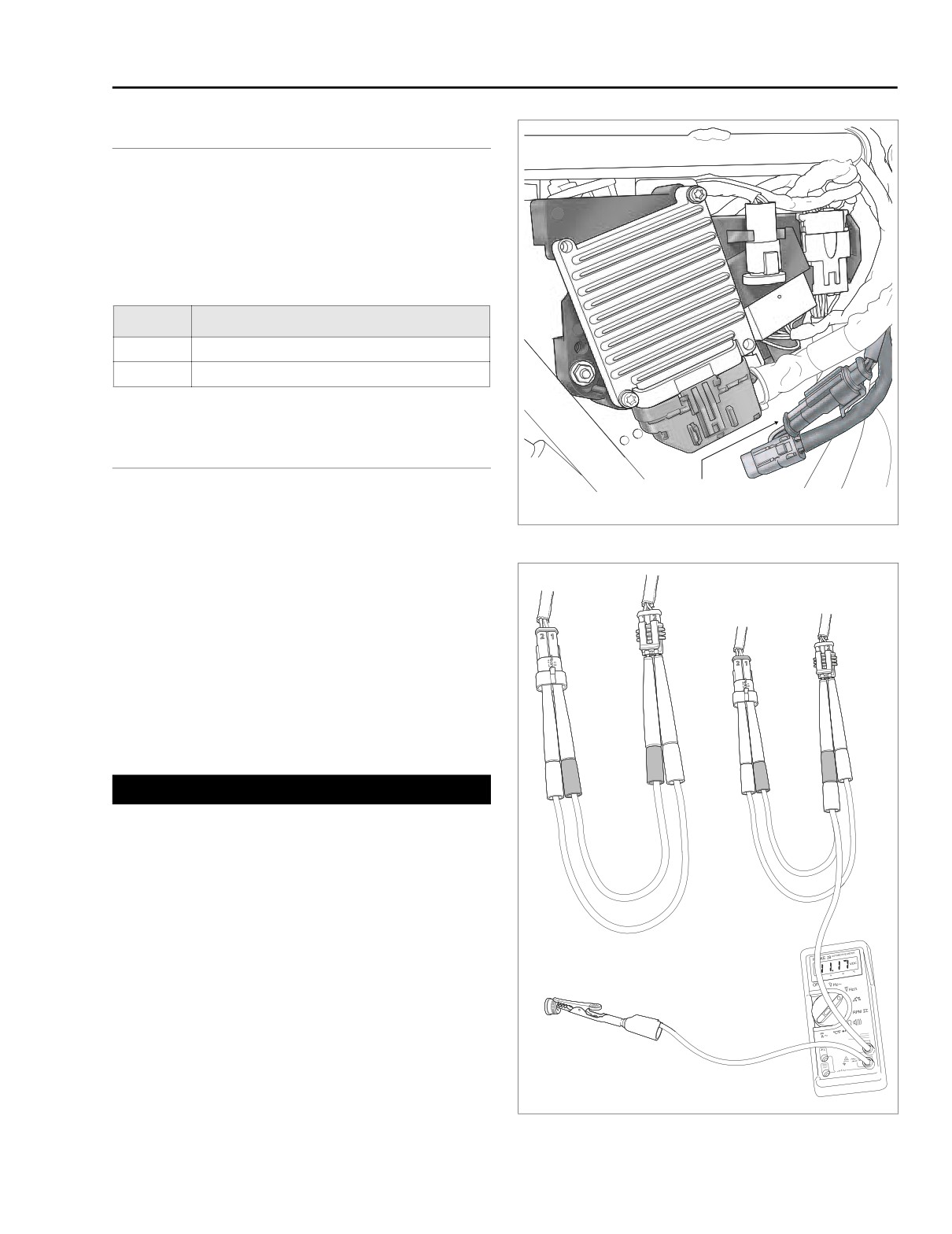
ABS LAMP ON CONTINUOUSLY
A.8
GENERAL
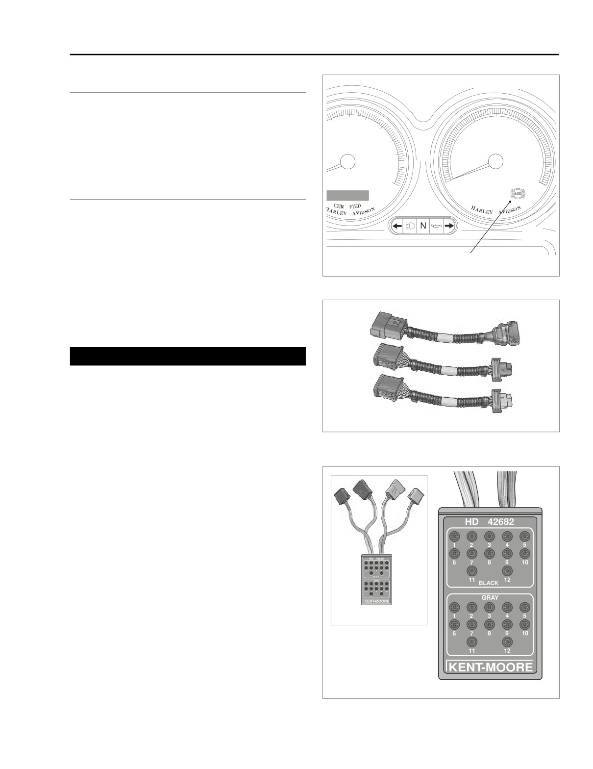
See Figure A-17. Under normal operation, the ABS lamp will
flash at key on and become extinguished at speeds greater
60
40
50
70
30
50
than 6 mph (9.7 kph). If the lamp stays on continuously, then
0
80
the lamp circuit may be faulty.
90
20
60
MPH
RPM x100
100
10
70
110
P
120
0
80
DIAGNOSTICS
TI
-D
-D
Diagnostic Notes
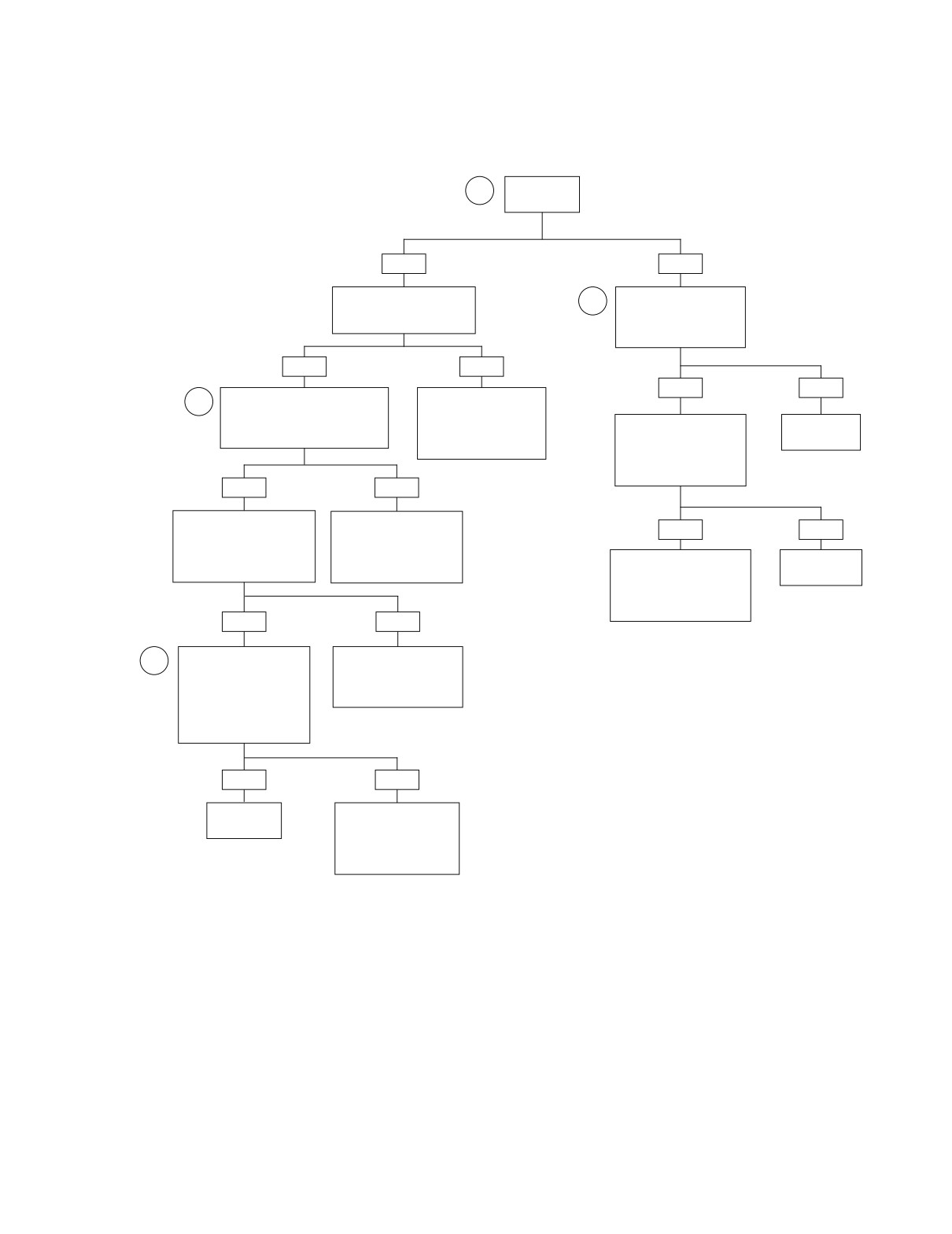
The reference numbers below correlate with the circled num-
bers on the Test A.8 flow chart.
ABS Lamp
f2306x8x
1. See Section A.5 ABS SELF DIAGNOSTICS, REPORT-
Figure A-17. Tachometer (FLHTP)
ING DTC’s.
2. Obtain DARK BLUE PIN PROBE (Part No. HD-41404-
46) and patch cord from HARNESS CONNECTOR TEST
KIT (Part No. HD-41404A).
1WARNING
Use only gray pin probes from HARNESS CONNECTOR
TEST KIT (Part No. HD-41404A) on small terminals (1-7,
10-23) of ABS Module connector [166B], and dark blue
pin probes on large terminals (8-9, 24-25). Use of the
HD46601
wrong probes can damage terminals causing insufficient
or excessive current to be passed to solenoid valves
and/or pump, a condition which could cause the ABS to
Figure A-18. Instrument Harness Adapters
malfunction, possibly resulting in death or serioius
(Part No. HD-46601)
injury.
3. Connect BREAKOUT BOX (Part No. HD-42682) and
INSTRUMENT HARNESS ADAPTERS (Part No. HD-
46601) between wire harness and tachometer. See Fig-
ure A-18 and Figure A-19.
f2001x8x
f1998x9x
Figure A-19. Breakout Box (Part No. HD-42682)
Appendix A: Anti-Lock Brake System A-17
HOME
ABS MODULE
[166A] [166B]
20 AMP FUSES
ABS SOLENOID POWER
8
R/V
R TO +BATT (TERMINAL B OF MAXI-FUSE)
9
R/V
ABS MOTOR/PUMP POWER
FUSE BLOCK [64]
FLHP/E FLHTP
FLHP/E Fuse Block
FLHTP Fuse Block
Wire
Wire
Fuse
Cavity
Color
20A
10A
20A
10A
Fuse
Cavity
Color
BRAKE
BRAKE
4H
R/V
RELAY
15A
20A
20A
RELAY
15A
15A
3H
R/V
Solenoid
START
Solenoid
4G
R
3G
R
RELAY
15A
15A
15A
15A
15A
15A
3B
R/V
4H
R/V
Motor
Motor
3A
R
15A
15A
15A
15A
15A
15A
15A
15A
4G
R
4
TACHOMETER
3
ABS LAMP
16
O/V
2
1
1
O/BN
4
R/BE
1
2
2
[108B]
8
21
O/BN
3
3
[108A]
8
[176A] [176B]
4
4
5
5
24
BK
1
1
6
6
25
BK
2
2
[176B] [176A]
[177A] [177B]
BK
FLHTP ONLY
FLHP/E ONLY
R/BE
2
FLHTP ONLY
TO BRAKE LIGHT
1
3
SWITCH
1
2
3
4
5
6
7
8
9
10
11
12
[1A]
[1B]
ABS MODULE PINOUT:
1
2
3
4
5
6
7
8
9
10
11
12
8
+BATTERY-SOLENOID POWER
ABS MODULE CONNECTOR [166A]
9
+BATTERY-MOTOR POWER
O/V
TO BRAKES/PURSUIT
16
IGNITION
FUSE
4
BRAKE SWITCH INPUT
21
ABS WARNING LAMP
24
GROUND
25
GROUND
ABS MODULE CONNECTOR [166B]
f2335b8x
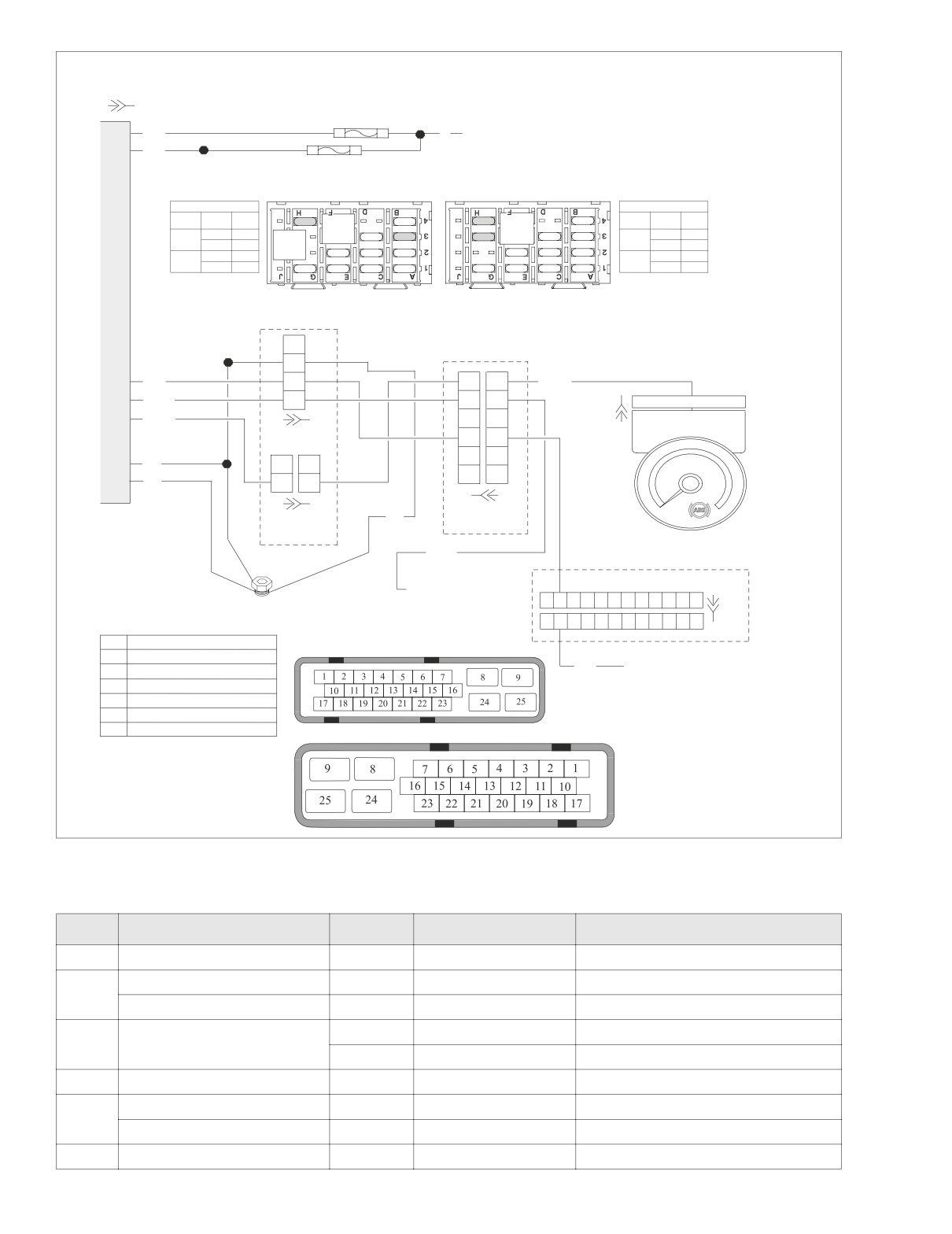
Figure A-20. ABS Lamp Circuit
Table A-5. Wire Harness Connectors in Figure A-20.
NO.
DESCRIPTION
MODEL
TYPE
LOCATION
[1]
Main to Interconnect Harness
FLHTP
12-place Deutsch
Inner Fairing (Right Fairing Bracket)
ABS Solenoid Power Fuse
All
20 Amp (Red)
Fuse Block (Under Left Side Cover)
[64]
ABS Motor/Pump Power Fuse
All
20 Amp (Red)
Fuse Block (Under Left Side Cover)
FLHP/E
12-place Packard
Back of Tachometer
[108]
Tachometer
FLHTP
12-place Packard
Inner Fairing (Back of Tachometer)
[166]
ABS Module
All
25-place Amp
Under Right Side Saddlebag
Main to Interconnect Harness
FLHTP
6-place Deutsch
Inner Fairing (Right Side)
[176]
Main to Main Harness
FLHP/E
4-place Deutsch
Under Left Side Cover
[177]
Main to Main Harness
FLHP/E
2-place Deutsch
Headlamp Nacelle (Left Side)
A-18
Appendix A: Anti-Lock Brake System
HOME
Test A.8 (Part 1 of 1)
ABS LAMP ON CONTINUOUSLY
Are DTC’s
1
present?
YES
NO
Go to applicable flow chart.
Measure voltage on
3
Correct and clear codes.
O/BN wire of terminal 8
Lamp still on continuously?
of connector [108B]. Is
voltage present?
YES
NO
YES
NO
Check for resistance between
Locate and repair high
2
socket 8 of connector [166B] and
resistance on BK wire
ABS solenoid power fuse.
between socket 24 of
Disconnect connector
Replace
Resistance less than 0.5 ohms?
connector [166B] and
[166]. Measure voltage on
tachometer.
ground.
O/BN wire of terminal 8 of
connector [108B]. Is
6772
2417
voltage still present?
YES
NO
Measure resistance on
Locate and repair high
R wire between ABS
resistance on R/V wire
YES
NO
solenoid power fuse and
between socket 8 of
battery. Resistance less
connector [166B] and
Locate and repair short to
Replace ABS
than 0.5 ohms?
ABS solenoid power fuse.
voltage between socket 21
module.
of connector [166B] and
2427
2430
terminal 8 of connector
[108B].
YES
NO
2447
Measure continuity on
Locate and repair high
3
O/BN wire between
resistance on R wire
socket 21 of connector
between ABS solenoid
[166B] and terminal 8 of
power fuse and battery.
connector [108B].
Resistance less than 0.5
2422
ohms?
YES
NO
Replace ABS
Locate and repair open
module.
between socket 21 of
connector [166B] and
2430
terminal 8 of
connector [108B].
2438
Appendix A: Anti-Lock Brake System A-19
HOME
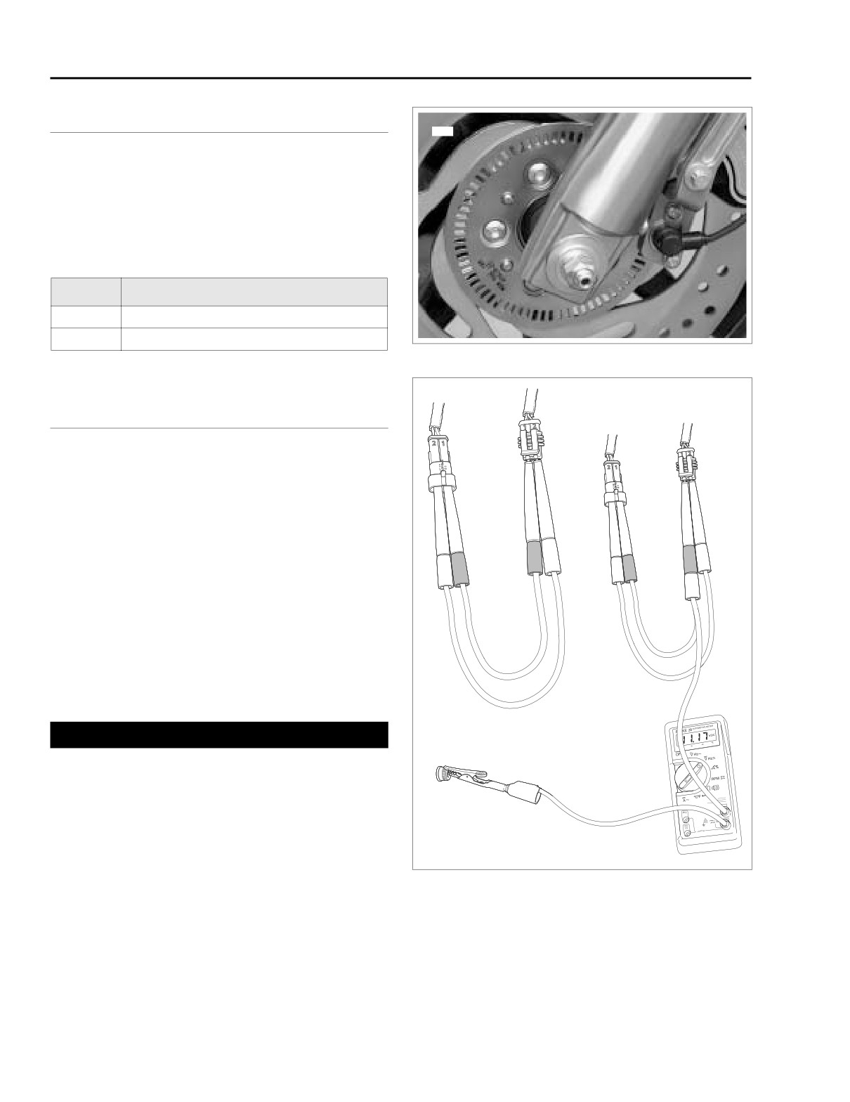
FRONT WHEEL SPEED SENSOR: DTC 1-1, 1-2
A.9
GENERAL
9469
Code 1-1 is set if the output voltage of the front wheel speed
sensor is lower than 0.3 volts or higher than 2.6 volts. Code 1-
2 is set if the output signals between the front and rear
wheels do not match a profile in the memory of the controller.
Table A-6. Code Description
DTC
DESCRIPTION
1-1
Failed Short/Open
1-2
Failed Intermittent/Signal Out of Specification
Figure A-21. Front Wheel Speed Sensor/Tone Ring
DIAGNOSTICS
A
B
Diagnostic Notes
The reference numbers below correlate with the circled num-
bers on the Test A.9 flow charts.
1.
Set up wheel speed sensor test as follows:
a. Obtain two gray pin probes, two gray socket probes
and two patch cords from HARNESS CONNECTOR
TEST KIT (Part No. HD-41404A).
b. Disconnect front wheel speed sensor connector
[167]. Maintaining polarity, use patch cords to con-
nect probes to pin and socket housings as shown in
A of Figure A-22.
2. Use HARNESS CONNECTOR TEST KIT (Part No. HD-
41404A), gray pin probes and patch cord.
1WARNING
Ground
Use only gray pin probes from HARNESS CONNECTOR
TEST KIT (Part No. HD-41404A) on small terminals (1-7,
10-23) of ABS Module connector [166B], and dark blue
pin probes on large terminals (8-9, 24-25). Use of the
wrong probes can damage terminals causing insufficient
or excessive current to be passed to solenoid valves
f2330x8x
and/or pump, a condition which could cause the ABS to
malfunction, possibly resulting in death or serioius
injury.
Figure A-22. Set Up Wheel Speed Sensor Test
3.
Code will set if clearance between wheel speed sensor
and tone ring exceeds 0.060 inch (1.524 mm). Rotate
wheel to check clearance in several places.
A-20
Appendix A: Anti-Lock Brake System
HOME
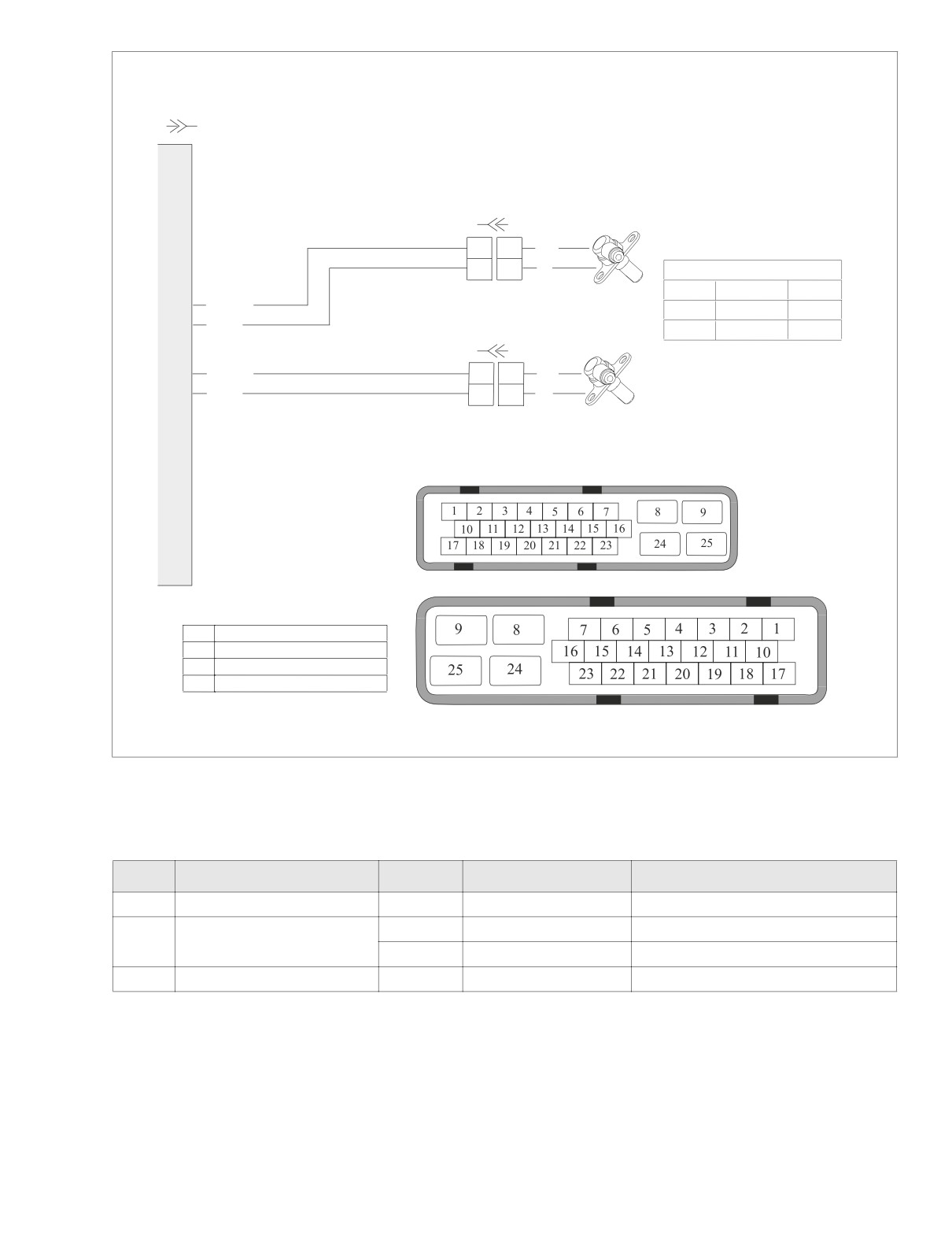
f2335c8x
ABS MODULE
[166A] [166B]
[167B] [167A]
FRONT WHEEL
SPEED SENSOR
1
1
BK
2
2
W
Wheel Speed Sensors
Cavity
Function
Color
12
BK/BE
1
Power
Black
3
BK/V
2
Ground
White
2
BE/BN
1
1
BK
REAR WHEEL
SPEED SENSOR
18
BE/V
2
2
W
[168B] [168A]
ABS MODULE CONNECTOR [166A]
ABS MODULE CONNECTOR [166B]
ABS MODULE PINOUT:
12
+FRONT WHEEL SENSOR
3
-FRONT WHEEL SENSOR
2
+REAR WHEEL SENSOR
18
-REAR WHEEL SENSOR
Figure A-23. Front Wheel Speed Sensor Circuit
Table A-7. Wire Harness Connectors in Figure A-23.
NO.
DESCRIPTION
MODEL
TYPE
LOCATION
[166]
ABS Module
All
25-place Amp
Under Right Side Saddlebag
FLHP/E
2-place Tyco
Headlamp Nacelle (Left Side)
[167]
Front Wheel Speed Sensor
FLHTP
2-place Tyco
Inner Fairing (Left Side)
[168]
Rear Wheel Speed Sensor
All
2-place Tyco
Under Right Side Cover
Appendix A: Anti-Lock Brake System A-21
HOME
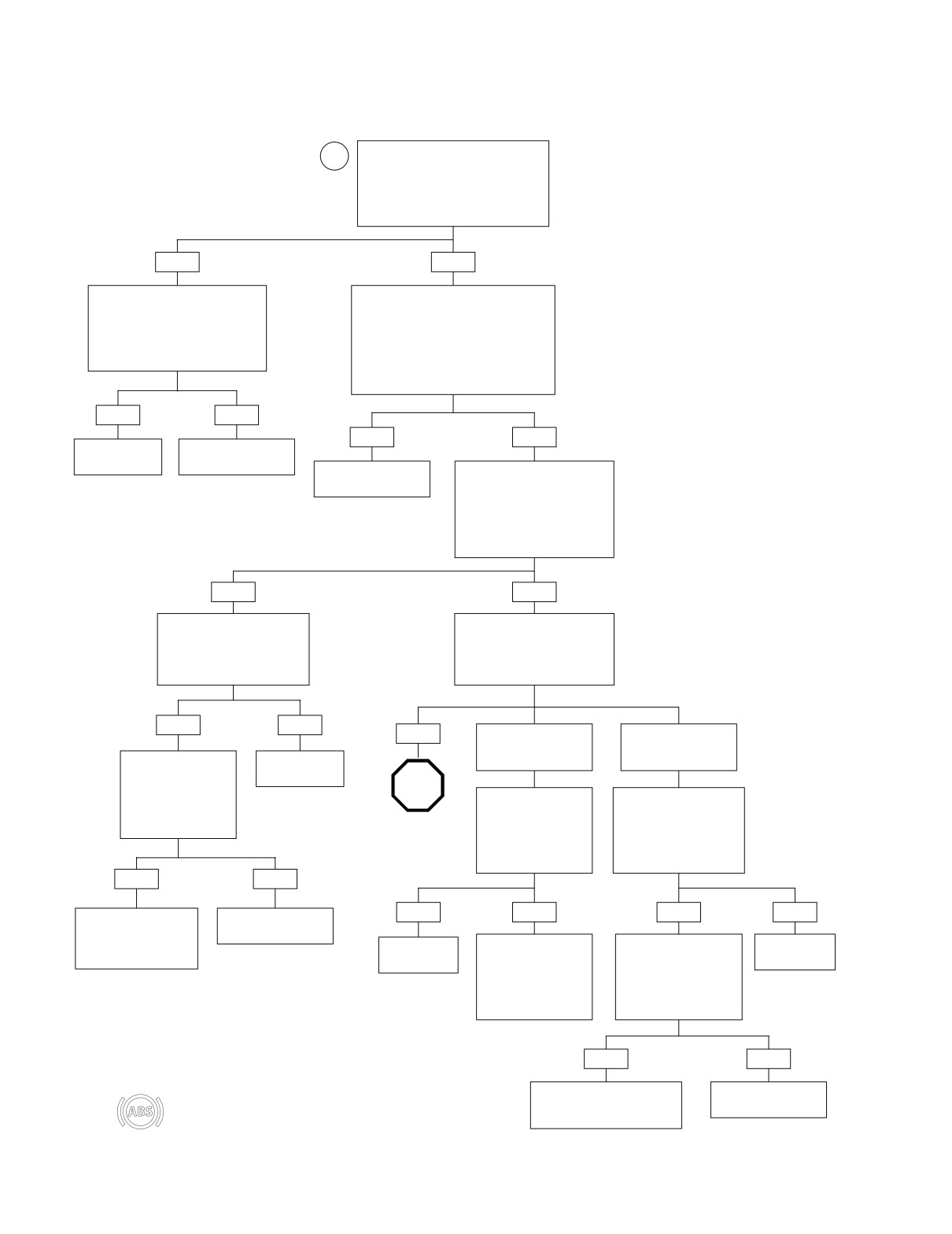
Test A.9a (Part 1 of 2)
FRONT WHEEL SPEED SENSOR: DTC 1-1
IMPORTANT NOTE
Set up wheel speed sensor test
Test results will only be accurate
1
between connector [167A] and [167B].
if battery is fully charged.
Turn ignition ON and measure voltage
between terminal 1 on connector [167]
and ground (-). See B of Figure A-22.
Is voltage over 10 VDC?
YES
NO
Support motorcycle securely on jack
Turn ignition OFF. Substitute known
or lift. Measure DC voltage between
good sensor or attach HD-41404A har-
terminal 2 (+) on connector [167]
ness connector test kit and cable adapt-
and ground (-). Does voltage fluctu-
ers from connectors [167B] to [168A]
ate between 0.4-0.9 and 1.1-2.1
(front harness to rear sensor). Turn igni-
VDC when front wheel is rotated?
tion ON. Measure voltage between termi-
nal 1 on connector [167] and ground (-).
Is voltage over 10 VDC?
YES
NO
YES
NO
Replace
Replace front
ABS module.
wheel speed sensor.
Replace front
Turn ignition OFF. Reconnect
2430
2439
wheel speed sensor.
front wheel speed sensor to
connector [167B]. Measure
2439
resistance between terminal 1
on connector [167] (+) and
ground (-). Is resistance less
than 200,000 ohms?
YES
NO
Disconnect connector [166B].
Turn ignition OFF. Measure
Measure resistance between
resistance between terminal 2
terminal 1 on connector [167B]
on connector [167] (+) and
and ground (-). Is continuity
ground (-). Is resistance
present?
between 100-200 ohms?
YES
NO
YES
NO
NO
Resistance is greater
Resistance is less than
Disconnect connector
Replace
than 200 ohms.
100 ohms.
[167A]. Measure resis-
ABS module.
tance between termi-
STOP
nal 1 on connector
2430
Measure resistance
Disconnect connector
[167B] and ground (-).
between socket 2 of
[166]. Measure resis-
Is continuity present?
Go to Test A.9a
connector [167B] and
tance between terminal 2
(Part 2 of 2).
socket 3 of connector
on connector [167] and
[166B]. Is continuity
ground (-). Is continuity
present?
present?
YES
NO
YES
NO
YES
NO
Locate and repair short
Replace front
to ground on BK/BE
wheel speed sensor.
wire between connec-
Replace
Locate and repair
Disconnect connector
Replace
tors [166B] and [167B].
2439
open on BK/V wire
[167]. Measure resis-
ABS module.
ABS module.
between socket 2 of
tance between terminal 2
2444
2430
2430
connector [167B] and
on connector [167] and
socket 3 of connector
ground (-). Is continuity
[166B].
present?
2445
YES
NO
Locate and repair short to
Replace front
After repair of motorcycle, perform Final Diag-
ground on BK/V wire between
wheel speed sensor.
nostic Check to confirm proper operation without
connectors [166B] and [167B].
setting codes. See Section A.6 INITIAL/FINAL
2439
DIAGNOSTIC CHECK.
2445
A-22
Appendix A: Anti-Lock Brake System
HOME
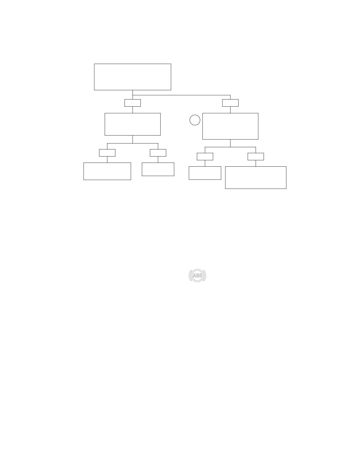
Test A.9a (Part 2 of 2)
FRONT WHEEL SPEED SENSOR: DTC 1-1
Continued from Test A.9a (Part 1 of 2).
Disconnect connector [167]. Measure
resistance between sockets 1 and 2 of
connector [167B]. Is resistance less than
100,000 ohms?
YES
NO
Disconnect connector [166B].
Disconnect connector [166B].
Measure resistance between
2
Measure resistance between
sockets 1 and 2 of connector
socket 1 of [167B] and socket
[167B]. Is continuity present?
12 of connector [166B].
Is continuity present?
YES
NO
YES
NO
Locate and repair short
Replace
between BK/BE and
ABS module.
Replace
Locate and repair open on BK/BE
BK/V wires.
ABS module.
wire between socket 1 of connec-
2430
tor [167B] and socket 12 of con-
2448
2430
nector [166B].
2444
After repair of motorcycle, perform Final Diag-
nostic Check to confirm proper operation without
setting codes. See Section A.6 INITIAL/FINAL
DIAGNOSTIC CHECK.
Appendix A: Anti-Lock Brake System A-23
HOME
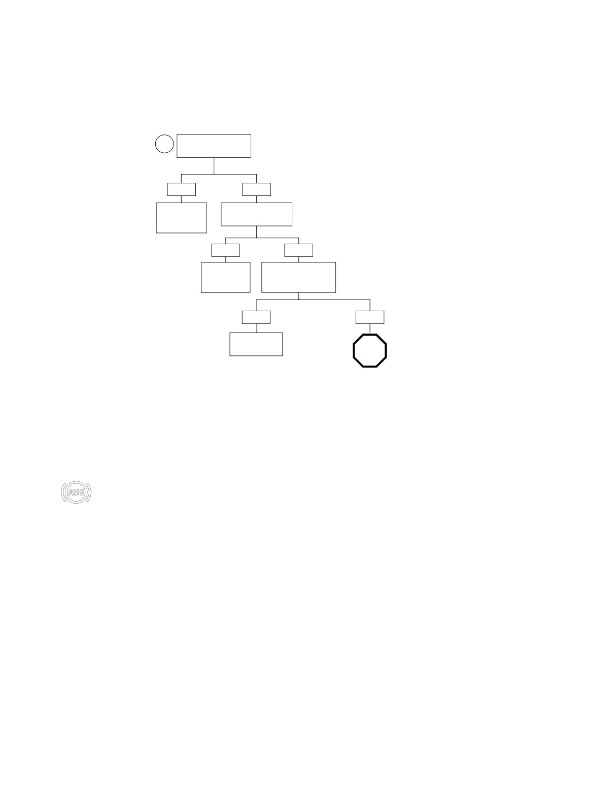
Test A.9b (Part 1 of 1)
FRONT WHEEL SPEED SENSOR: DTC 1-2
Is front wheel speed
3
sensor loose?
YES
NO
Tighten front
Is front wheel speed
wheel speed
sensor damaged?
sensor.
2458
YES
NO
Replace front
Inspect tone ring. Is
wheel speed
tone ring loose or
sensor.
damaged?
2469
YES
NO
Replace brake
disc.
STOP
2450
Go to Test A.9a
(Part 1 of 2).
After repair of motorcycle, perform Final Diag-
nostic Check to confirm proper operation without
setting codes. See Section A.6 INITIAL/FINAL
DIAGNOSTIC CHECK.
A-24
Appendix A: Anti-Lock Brake System
HOME
REAR WHEEL SPEED SENSOR: DTC 1-3, 1-4
A.10
GENERAL
f2314x8x
Code 1-3 is set if the output voltage of the rear wheel speed
sensor is lower than 0.3 volts or higher than 2.6 volts. Code 1-
4 is set if the output signals between the front and rear
wheels do not match a profile in the memory of the controller.
Table A-8. Code Description
DTC
DESCRIPTION
1-3
Failed Short/Open
1-4
Failed Intermittent/Signal Out of Specification
DIAGNOSTICS
Rear Wheel
Diagnostic Notes
Speed Sensor [168]
The reference numbers below correlate with the circled num-
Figure A-24. Remove Right Side Cover
bers on the Test A.10 flow charts.
1. Set up wheel speed sensor test as follows:
a. Obtain two gray pin probes, two gray socket probes
A
B
and two patch cords from HARNESS CONNECTOR
TEST KIT (Part No. HD-41404A).
b. Disconnect rear wheel speed sensor connector
[168]. Maintaining polarity, use patch cords to con-
nect probes to pin and socket housings as shown in
A of Figure A-25.
2. Use HARNESS CONNECTOR TEST KIT (Part No. HD-
41404A), gray pin probes and patch cord.
1WARNING
Use only gray pin probes from HARNESS CONNECTOR
TEST KIT (Part No. HD-41404A) on small terminals (1-7,
10-23) of ABS Module connector [166B], and dark blue
pin probes on large terminals (8-9, 24-25). Use of the
wrong probes can damage terminals causing insufficient
or excessive current to be passed to solenoid valves
and/or pump, a condition which could cause the ABS to
malfunction, possibly resulting in death or serioius
injury.
Ground
3. Code will set if clearance between wheel speed sensor
and tone ring exceeds 0.060 inch (1.524 mm). Rotate
wheel to check clearance in several places.
f2330x8x
Figure A-25. Set Up Wheel Speed Sensor Test
Appendix A: Anti-Lock Brake System A-25
HOME
f2335c8x
ABS MODULE
[166A] [166B]
[167B] [167A]
FRONT WHEEL
SPEED SENSOR
1
1
BK
2
2
W
Wheel Speed Sensors
Cavity
Function
Color
12
BK/BE
1
Power
Black
3
BK/V
2
Ground
White
2
BE/BN
1
1
BK
REAR WHEEL
SPEED SENSOR
18
BE/V
2
2
W
[168B] [168A]
ABS MODULE CONNECTOR [166A]
ABS MODULE CONNECTOR [166B]
ABS MODULE PINOUT:
12
+FRONT WHEEL SENSOR
3
-FRONT WHEEL SENSOR
2
+REAR WHEEL SENSOR
18
-REAR WHEEL SENSOR
Figure A-26. Rear Wheel Speed Sensor Circuit
Table A-9. Wire Harness Connectors in Figure A-26.
NO.
DESCRIPTION
MODEL
TYPE
LOCATION
[166]
ABS Module
All
25-place Amp
Under Right Side Saddlebag
FLHP/E
2-place Tyco
Headlamp Nacelle (Left Side)
[167]
Front Wheel Speed Sensor
FLHTP
2-place Tyco
Inner Fairing (Left Side)
[168]
Rear Wheel Speed Sensor
All
2-place Tyco
Under Right Side Cover
A-26
Appendix A: Anti-Lock Brake System
HOME
Test A.10a (Part 1 of 2)
REAR WHEEL SPEED SENSOR: DTC 1-3
IMPORTANT NOTE
Set up wheel speed sensor test
Test results will only be accurate
1
between connector [168A] and [168B].
if battery is fully charged.
Turn ignition ON and measure voltage
between terminal 1 on connector [168]
and ground (-). See B of Figure A-25.
Is voltage over 10 VDC?
YES
NO
Support motorcycle securely on
Turn ignition OFF. Substitute known
jack or lift. Measure DC voltage
good sensor or attach HD-41404A har-
between terminal 2 (+) on con-
ness connector test kit and cable adapt-
nector [168] and ground (-). Does
ers from connectors [168B] to [167A]
voltage fluctuate between 0.4-0.9
(rear harness to front sensor). Turn igni-
and 1.1-2.1 VDC when rear
tion ON. Measure voltage between termi-
wheel is rotated?
nal 1 on connector [168] and ground (-).
Is voltage over 10 VDC?
YES
NO
YES
NO
Replace
Replace rear
ABS module.
wheel speed sensor.
Replace rear
Turn ignition OFF. Reconnect
wheel speed sensor.
rear wheel speed sensor to con-
2430
2470
nector [168B]. Measure resis-
2470
tance between terminal 1 on
connector [168] (+) and ground
(-). Is resistance less than
200,000 ohms?
YES
NO
Disconnect connector [166B].
Turn ignition OFF. Measure
Measure resistance between
resistance between terminal 2
terminal 1 on connector [168B]
on connector [168] (+) and
and ground (-). Is continuity
ground (-). Is resistance
present?
between 100-200 ohms?
YES
NO
YES
NO
NO
Resistance is greater
Resistance is less than
than 200 ohms.
100 ohms.
Disconnect connector
Replace
[168A]. Measure resis-
ABS module.
STOP
tance between termi-
2430
Measure resistance
Disconnect connector
nal 1 on connector
between socket 2 of
[166]. Measure resis-
[168B] and ground (-).
Go to Test A.10a
connector [168B] and
tance between terminal 2
Is continuity present?
(Part 2 of 2).
socket 18 of connec-
on connector [168] and
tor [166B]. Is continuity
ground (-). Is continuity
present?
present?
YES
NO
YES
NO
YES
NO
Locate and repair short
Replace rear
to ground on BE/BN
wheel speed sensor.
Replace
Locate and repair
Disconnect connector
Replace
wire between connec-
2440
open on BE/V wire
[168]. Measure resis-
ABS module.
tors [166B] and [168B].
ABS module.
between socket 2 of
tance between terminal 2
2454
2430
connector [168B] and
on connector [168] and
2430
socket 18 of connec-
ground (-). Is continuity
tor [166B].
present?
2455
YES
NO
After repair of motorcycle, perform Final Diag-
nostic Check to confirm proper operation without
Locate and repair short to
Replace rear
setting codes. See Section A.6 INITIAL/FINAL
ground on BE/V wire between
wheel speed sensor.
DIAGNOSTIC CHECK.
connectors [166B] and [168B].
2440
2455
Appendix A: Anti-Lock Brake System A-27
HOME
Test A.10a (Part 2 of 2)
REAR WHEEL SPEED SENSOR: DTC 1-3
Continued from Test A.10a (Part 1 of 2).
Disconnect connector [168]. Measure
resistance between sockets 1 and 2 of
connector [168B]. Is resistance less than
100,000 ohms?
YES
NO
Disconnect connector [166B].
Disconnect connector [166B].
2
Measure resistance between
Measure resistance between
sockets 1 and 2 of connector
socket 1 of [168B] and socket
[168B]. Is continuity present?
2 of connector [166B].
Is continuity present?
YES
NO
YES
NO
Locate and repair short
Replace
between BE/BN and
ABS module.
Replace
Locate and repair open on BE/BN
BE/V wires.
ABS module.
wire between socket 1 of connec-
2430
tor [168B] and socket 2 of con-
2457
2430
nector [166B].
2454
After repair of motorcycle, perform Final Diag-
nostic Check to confirm proper operation without
setting codes. See Section A.6 INITIAL/FINAL
DIAGNOSTIC CHECK.
A-28
Appendix A: Anti-Lock Brake System
HOME
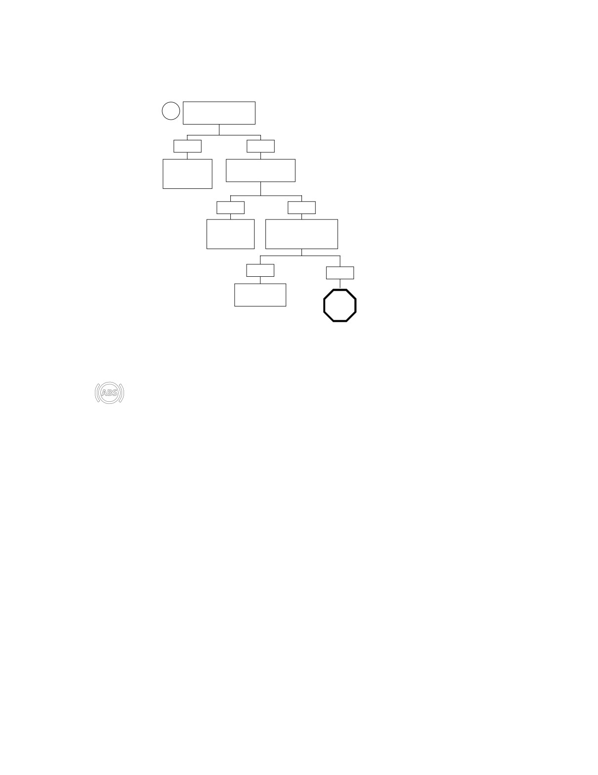
Test A.10b (Part 1 of 1)
REAR WHEEL SPEED SENSOR: DTC 1-4
Is rear wheel speed
3
sensor loose?
YES
NO
Tighten rear
Is rear wheel speed
wheel speed
sensor damaged?
sensor.
2458
YES
NO
Replace rear
Inspect tone ring. Is
wheel speed
tone ring loose or
sensor.
damaged?
2470
YES
NO
Replace brake
disc.
STOP
2452
Go to Test A.10a
(Part 1 of 2).
After repair of motorcycle, perform Final Diag-
nostic Check to confirm proper operation without
setting codes. See Section A.6 INITIAL/FINAL
DIAGNOSTIC CHECK.
Appendix A: Anti-Lock Brake System A-29
HOME
FRONT/REAR TONE RING: DTC 2-1, 2-3
A.11
GENERAL
9469
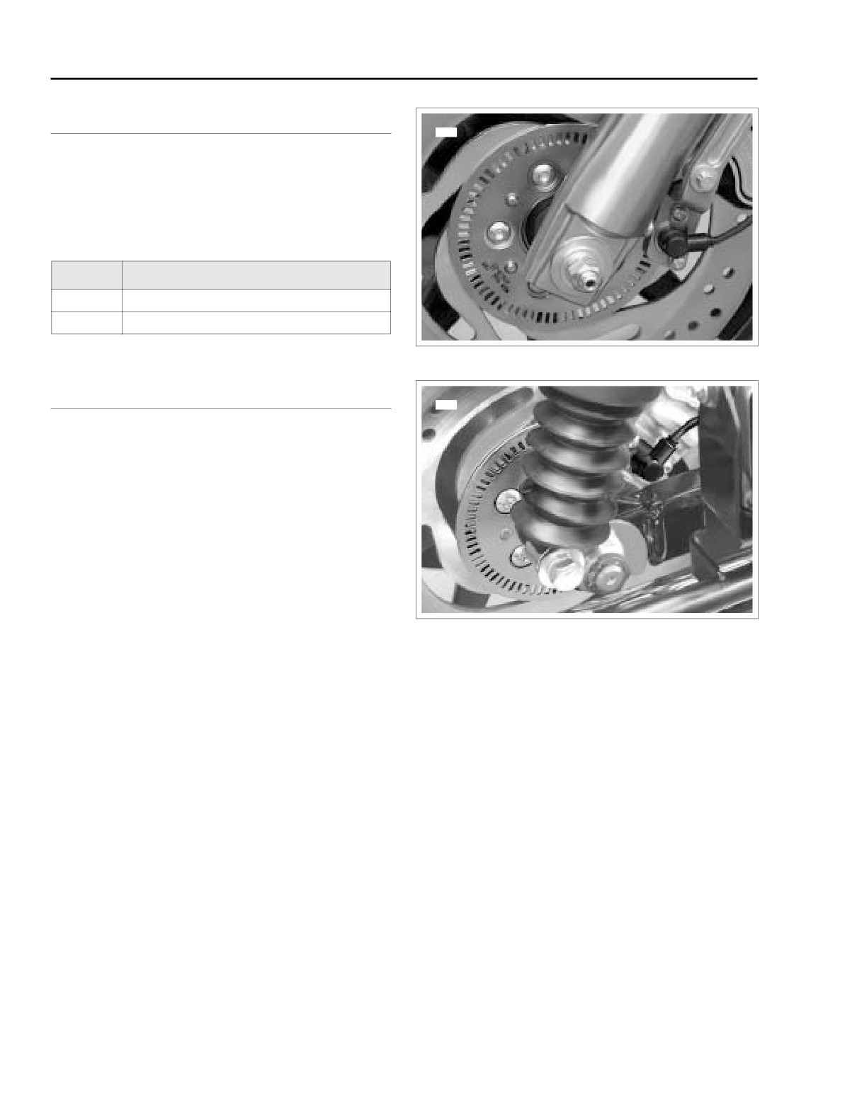
If front and rear wheel speed differs by more than 3.7 mph (6
kph) at vehicle speeds lower than 12.4 mph (20 kph) then the
code is set.
Table A-10. Code Description
DTC
DESCRIPTION
2-1
Front Tone Ring Deformation/Damage
2-3
Rear Tone Ring Deformation/Damage
Figure A-27. Front Wheel Speed Sensor/Tone Ring
DIAGNOSTICS
9461
Diagnostic Notes
The reference numbers below correlate with the circled num-
bers on the Test A.11 flow chart.
1.
Code will set if clearance between wheel speed sensor
and tone ring exceeds 0.060 inch (1.524 mm). Rotate
wheel to check clearance in several places.
Figure A-28. Rear Wheel Speed Sensor/Tone Ring
A-30
Appendix A: Anti-Lock Brake System
HOME
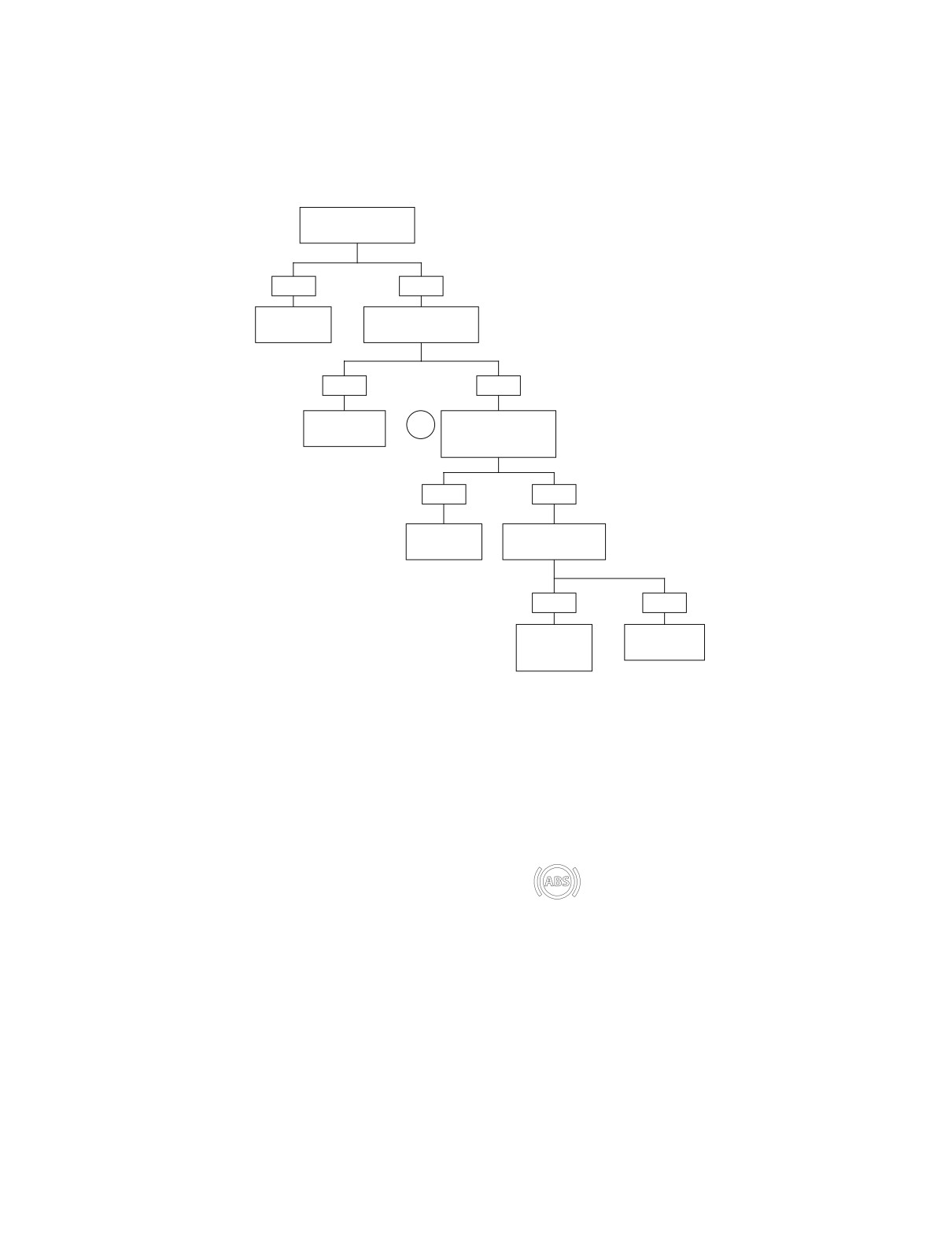
Test A.11 (Part 1 of 1)
FRONT/REAR TONE RING: DTC 2-1, 2-3
Inspect tone ring. Is
debris present?
YES
NO
Clean tone
Is tone ring loose or
ring.
damaged?
2460
YES
NO
Replace brake
Inspect wheel speed
1
disc.
sensor. Is wheel
speed sensor loose?
Front 2450
Rear 2452
YES
NO
Tighten wheel
Is wheel speed
speed sensor.
sensor damaged?
2458
YES
NO
Replace
Replace ABS
wheel speed
module.
sensor.
2430
Front 2469
Rear 2470
After repair of motorcycle, perform Final Diag-
nostic Check to confirm proper operation without
setting codes. See Section A.6 INITIAL/FINAL
DIAGNOSTIC CHECK.
Appendix A: Anti-Lock Brake System A-31
HOME
SOLENOID: DTC 3-1, 3-2, 3-3, 3-4
A.12
GENERAL
2
FLHP/E
The code will set when the drive and feedback signals of the
solenoid valve differ by more than 120 milliseconds, or when
the inlet and outlet valves stay on for an extended period.
1
Table A-11. Code Description
DTC
DESCRIPTION
3-1
Rear-In Solenoid Open/Short
f2305x8x
3-2
Rear-Out Solenoid Open/Short
3-3
Front-In Solenoid Open/Short
FLHTP
3-4
Front-Out Solenoid Open/Short
2
DIAGNOSTICS
1
Diagnostic Notes
The reference numbers below correlate with the circled num-
f2303x8x
1.
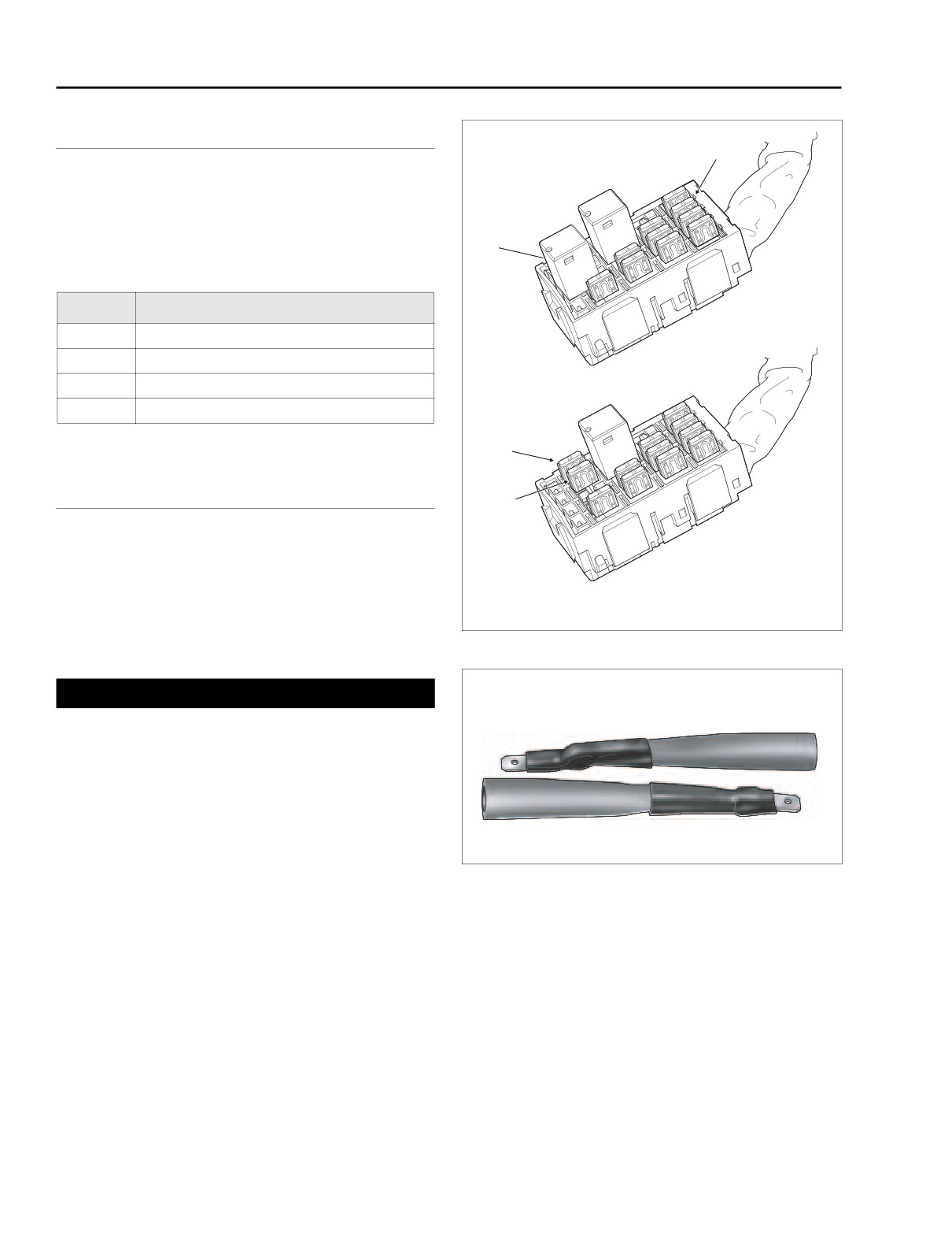
ABS Solenoid Power
bers on the Test A.12 flow chart.
2.
ABS Motor/Pump Power
1.
Obtain DARK BLUE PIN PROBES (Part No. HD-41404-
46) and patch cord from HARNESS CONNECTOR TEST
Figure A-29. Fuse Locations
KIT (Part No. HD-41404A).
HD41404-46
1WARNING
Use only gray pin probes from HARNESS CONNECTOR
TEST KIT (Part No. HD-41404A) on small terminals (1-7,
10-23) of ABS Module connector [166B], and dark blue
pin probes on large terminals (8-9, 24-25). Use of the
wrong probes can damage terminals causing insufficient
or excessive current to be passed to solenoid valves
and/or pump, a condition which could cause the ABS to
malfunction, possibly resulting in death or serioius
injury.
Figure A-30. Dark Blue Pin Probes (Part No. HD-41404-46)
A-32
Appendix A: Anti-Lock Brake System
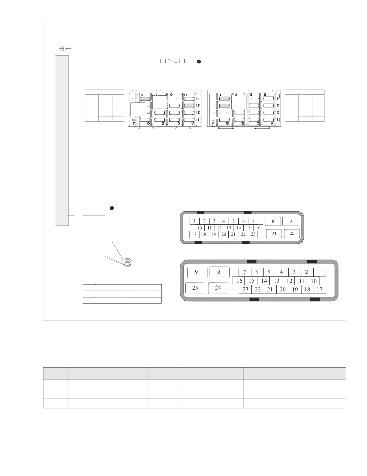
HOME
f2335d8x
ABS MODULE
[166A] [166B]
20 AMP FUSE
ABS SOLENOID POWER
8
R/V
R TO +BATT (TERMINAL B OF MAXI-FUSE)
FUSE BLOCK [64]
FLHP/E
FLHTP
FLHP/E Fuse Block
FLHTP Fuse Block
Wire
Wire
Fuse
Cavity
Color
20A
10A
20A
10A
Fuse
Cavity
Color
BRAKE
BRAKE
4H
R/V
RELAY
15A
20A
20A
RELAY
15A
15A
3H
R/V
Solenoid
START
Solenoid
4G
R
3G
R
RELAY
15A
15A
15A
15A
15A
15A
3B
R/V
4H
R/V
Motor
Motor
3A
R
15A
15A
15A
15A
15A
15A
15A
15A
4G
R
ABS MODULE CONNECTOR [166A]
24
BK
25
BK
ABS MODULE CONNECTOR [166B]
2
1
ABS MODULE PINOUT:
8
+BATTERY-SOLENOID POWER
24
GROUND
25
GROUND
Figure A-31. ABS Solenoid Power Circuit
Table A-12. Wire Harness Connectors in Figure A-31.
NO.
DESCRIPTION
MODEL
TYPE
LOCATION
ABS Solenoid Power Fuse
All
20 Amp (Red)
Fuse Block (Under Left Side Cover)
[64]
ABS Motor/Pump Power Fuse
All
20 Amp (Red)
Fuse Block (Under Left Side Cover)
[166]
ABS Module
All
25-place Amp
Under Right Side Saddlebag
Appendix A: Anti-Lock Brake System A-33
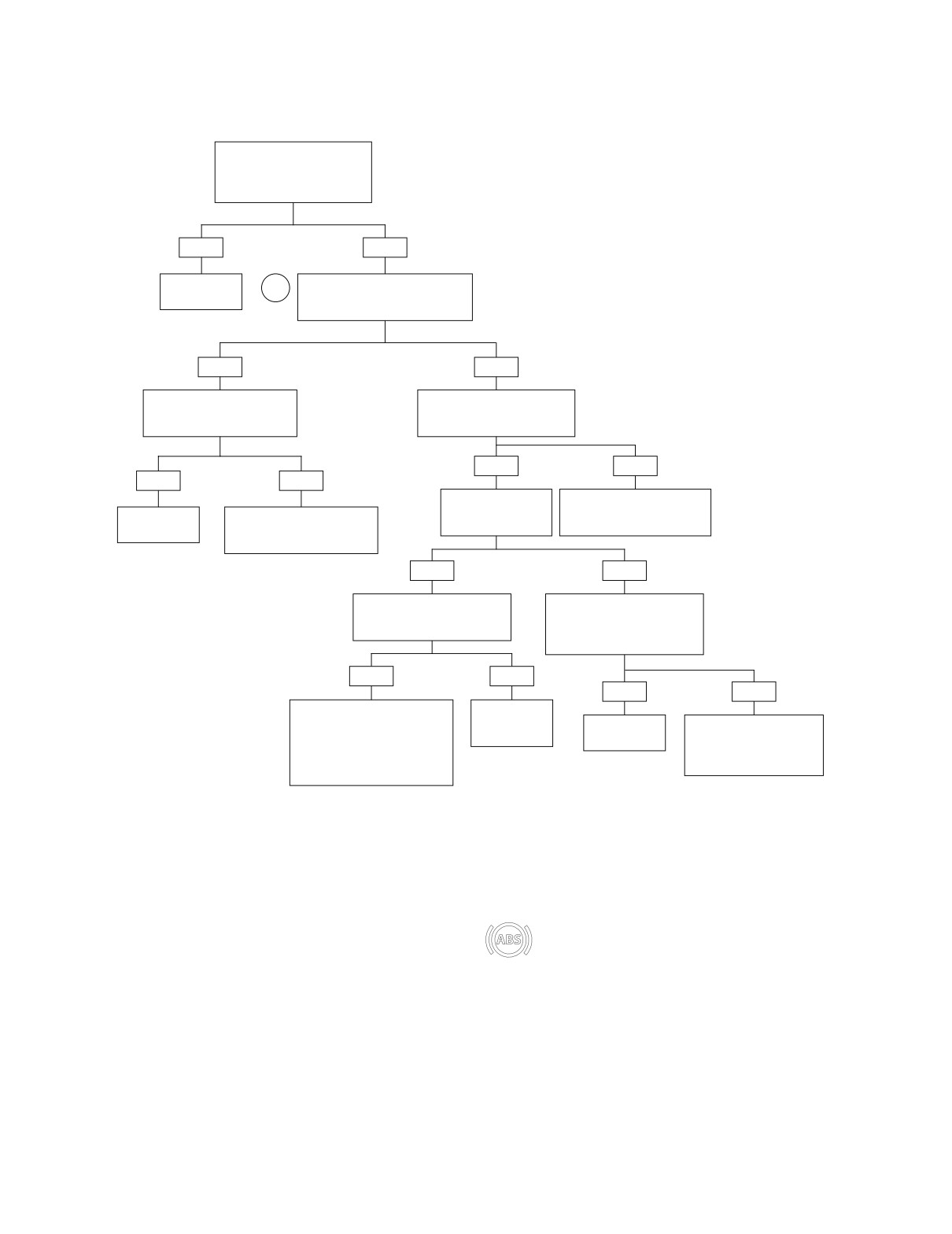
HOME
Test A.12 (Part 1 of 1)
SOLENOID: DTC 3-1, 3-2, 3-3, 3-4
With the ignition switch ON,
place hand on ABS module.
Does ABS module vibrate like
internal motor is running?
YES
NO
Replace ABS
Check for voltage between sock-
1
module.
ets 8 (+) and 25 (-) of connector
[166B]. Is battery voltage present?
2430
YES
NO
Check for continuity to ground
Check for continuity to ground
on socket 24 of connector
on socket 25 of connector
[166B]. Continuity present?
[166B]. Continuity present?
YES
NO
YES
NO
Check for blown ABS
Locate and repair open on BK
solenoid power fuse.
wire between socket 25 of
Replace ABS
Locate and repair open on BK
Fuse blown?
connector [166B] and ground.
module.
wire between socket 24 of
connector [166B] and ground.
2417
2430
2417
YES
NO
Check for continuity to ground
Check for continuity to ground
on socket 8 of connector
on socket 8 of connector
[166B]. Continuity present?
[166B] to ABS solenoid power
fuse. Continuity present?
YES
NO
YES
NO
Locate and repair short to
Replace ABS
ground on R/V wire between
solenoid power
Replace ABS
Locate and repair open on
socket 8 of connector [166B]
fuse.
module.
R/V wire between socket 8
and ABS solenoid power fuse.
of connector [166B] and
2459
Replace ABS solenoid power
2430
ABS solenoid power fuse.
fuse.
2427
2427
After repair of motorcycle, perform Final Diag-
nostic Check to confirm proper operation without
setting codes. See Section A.6 INITIAL/FINAL
DIAGNOSTIC CHECK.
A-34
Appendix A: Anti-Lock Brake System
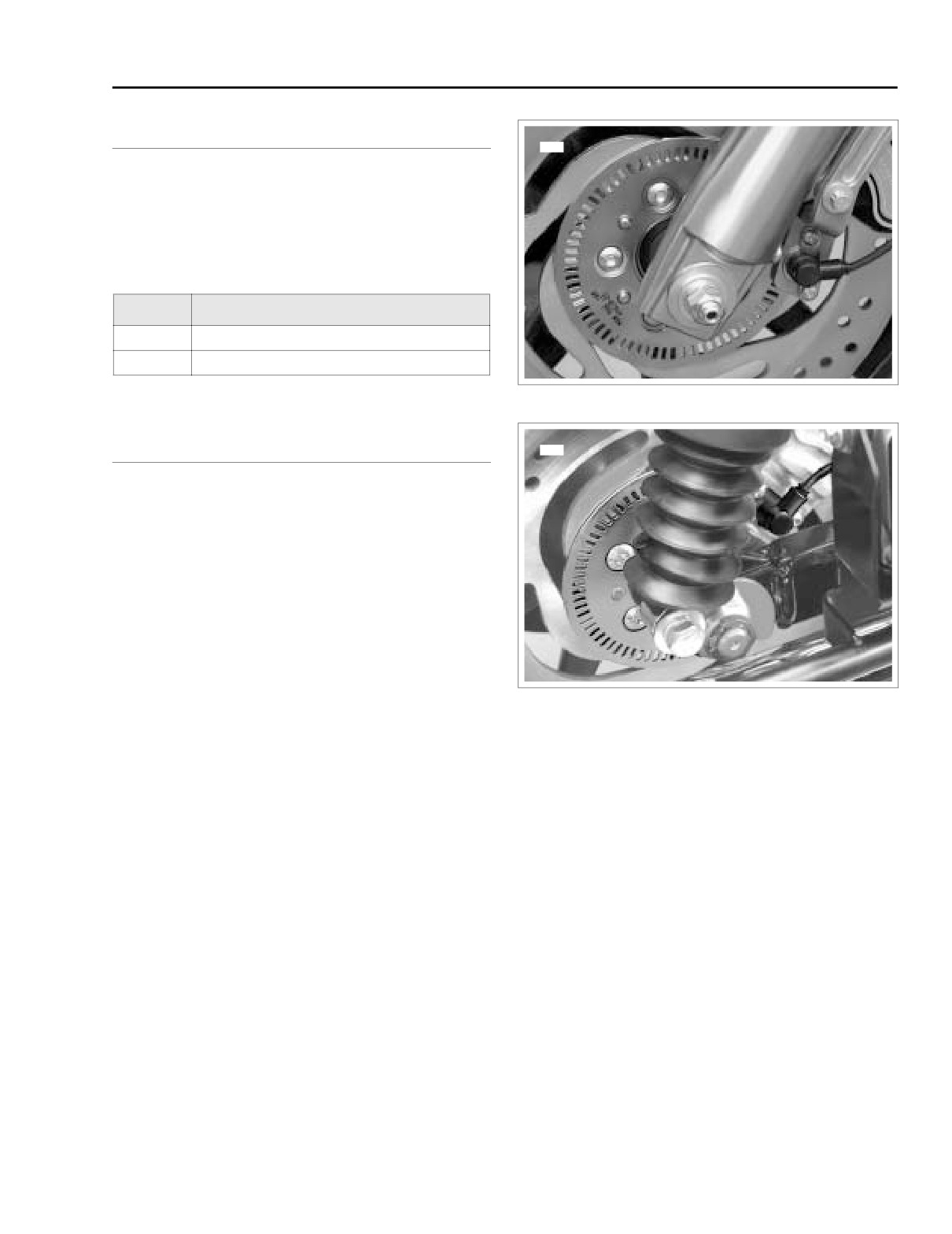
HOME
FRONT/REAR CALIPER: DTC 4-1, 4-3
A.13
GENERAL
9469
The codes will set when the ABS module sees a significant
difference between the speeds of the front and rear wheels
for an extended period.
Table A-13. Code Description
DTC
DESCRIPTION
4-1
Front Caliper Wheel Locks
4-3
Rear Caliper Wheel Locks
Figure A-32. Front Wheel Speed Sensor/Tone Ring
DIAGNOSTICS
9461
Diagnostic Notes
The reference numbers below correlate with the circled num-
bers on the Test A.13 flow chart.
1. Code will set if clearance between wheel speed sensor
and tone ring exceeds 0.060 inch (1.524 mm). Rotate
wheel to check clearance in several places.
Figure A-33. Rear Wheel Speed Sensor/Tone Ring
Appendix A: Anti-Lock Brake System A-35
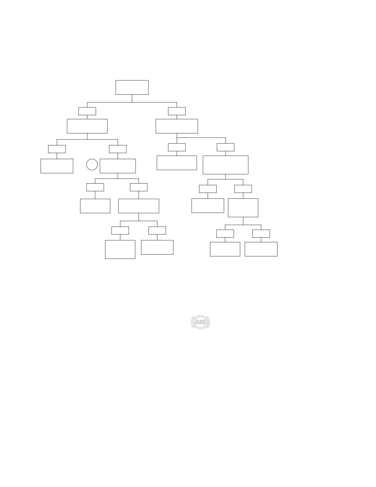
HOME
Test A.13 (Part 1 of 1)
FRONT/REAR CALIPER: DTC 4-1, 4-3
Does wheel
rotate freely?
YES
NO
Is tone ring loose
Does brake lever
or damaged?
have any free play?
YES
NO
YES
NO
Repair or replace
Loosen banjo bolt at
Replace brake
Is wheel speed
1
master cylinder.
brake caliper. Does
disc.
sensor loose?
wheel rotate freely?
Front 2483
Front 2450
Rear 2478
Rear 2452
YES
NO
YES
NO
Tighten wheel
Is wheel speed
Replace ABS
Is brake disc
speed sensor.
sensor damaged?
module.
bent or
warped?
2458
2430
YES
NO
YES
NO
Replace
Replace ABS
Replace brake
Replace brake
wheel speed
module.
disc.
caliper.
sensor.
2430
Front 2450
Front 2482
Front 2469
Rear 2470
Rear 2452
Rear 2481
After repair of motorcycle, perform Final Diag-
nostic Check to confirm proper operation without
setting codes. See Section A.6 INITIAL/FINAL
DIAGNOSTIC CHECK.
A-36
Appendix A: Anti-Lock Brake System