Harley Davidson 2005 touring models. Service repair manual - page 60
HOME
9.
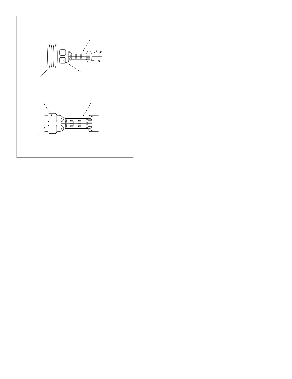
Position the insulation/seal crimp on the appropriate
nest. Be sure the insulation/seal crimp tails are facing
SEALED TERMINAL
the forming jaws.
Core Crimp
10. Squeeze handle of crimp tool until tightly closed. Tool
automatically opens when the crimping sequence is
complete.
11. Inspect the quality of the core and insulation/seal
crimps. Distortion should be minimal. See Figure 8-54.
Seal Crimp
Seal
f1006a8x
f1005a8x
Insulation
Crimp
Core Crimp
Insulation
NON-SEALED TERMINAL
Figure 8-54. Inspect Core and Insulation/Seal Crimps
8-36
2005 Touring: Wiring
HOME
AUTOFUSE ELECTRICAL CONNECTOR
8.5
GENERAL
8821
Use these instructions to service the following connector:
● HDI Ignition Light/Key Switch Jumper Harness [33D]
DISASSEMBLY
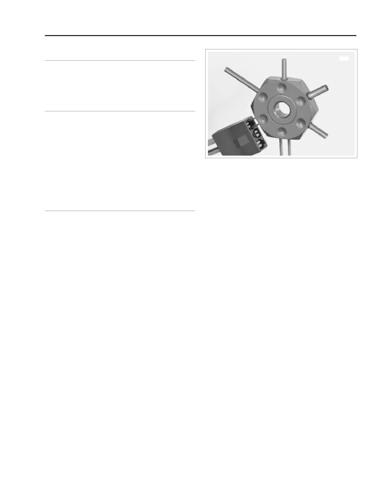
1. Obtain terminal pick
(Snap-on® GA500A) like that
shown Figure 8-55.
2. Insert smallest pair of pins into chamber on mating end
of socket housing to depress tangs on each side of ter-
minal simultaneously.
3. Gently pull on wire to remove terminal from wire end of
Figure 8-55. Depress Tangs and Remove Terminal
socket housing.
4. If necessary, crimp new terminals on wires.
ASSEMBLY
1. Using a thin flat blade, like that on an X-Acto knife, care-
fully bend tang on each side of terminal outward away
from terminal body.
2. With the open side of the terminal facing rib on wire end
of socket housing, insert terminal into chamber until it
locks in place.
2005 Touring: Wiring
8-37
HOME
SEALED BUTT SPLICE CONNECTORS
8.6
8. Repeat steps 5, 6 and 7 on the other side of the butt
PROCEDURE
splice connector.
Butt splicing may be a necessary procedure for the replace-
NOTE
ment of some components. Proceed as follows:
If adjacent wires are being spliced, stagger the splices so
1.
Strip 3/8 inch (9.5 mm) of insulation off the ends of the
that the butt splice connectors are spaced at different posi-
wires.
tions along the length of the wires.
2.
Compress the handles of the Packard Crimp Tool (HD-
38125-8) until the ratchet automatically opens.
9.
Using the UltraTorch UT-100 (HD-39969), Robinair Heat
3.
Since the size of the connectors vary with the gauge of
Gun
(HD-25070) with heatshrink attachment
(HD-
the wire, reference the following table to ensure properly
41183) or other suitable radiant heating device, heat the
sealed splices are used.
crimped splice to encapsulate the butt splice connection.
Apply heat from the center of the crimp out to each end
until the meltable sealant exudes out both ends of the
Gauge
Connector
Part
connector. See Figure 8-57.
Wire
Color
Number
18-20
Red
P/N 70585-93
14-16
Blue
P/N 70586-93
Red
10-12
Yellow
P/N 70587-93
4.
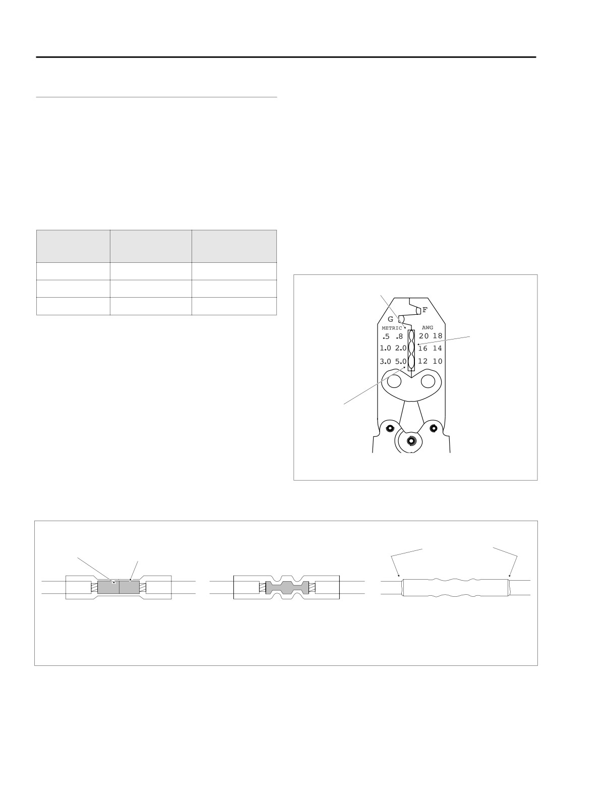
Determine the correct dye or nest for the crimping oper-
Blue
ation. Match the color or gauge wire marked on the butt
splice connector with the corresponding crimp cavity on
the crimp tool. See Figure 8-56.
5.
Gently apply pressure to the handles until the crimper
lightly secures one side of the metal insert inside the butt
splice connector. The connector must be crimped in two
Yellow
stages, one side and then the other.
6.
See Figure 8-57. Feed the wire into the butt splice con-
nector until the stripped end contacts the wire stop
inside the metal insert.
7.
Squeeze the handles of the crimp tool until tightly
closed. The tool automatically opens when the crimping
se-quence is complete.
Figure 8-56. Packard Crimp Tool (HD-38125-8)
Wire
Metal
Melted Sealant
Stop
Insert
Insert stripped wire
Crimp wire ends
Apply heat and allow
ends into connector
in connector
connector to cool
f1203b8x
Figure 8-57. Installing Sealed Butt Splice Connectors
8-38
2005 Touring: Wiring
HOME
NOTE
1WARNING
It is acceptable for the splice to rest against the heat shrink
tool attachment.
Use extreme caution when operating the UltraTorch UT-
100 or any other radiant heating device. Read the manu-
10. Heat the center of the splice until the crimp indentations
facturers instructions carefully before use. Always keep
disappear and the tubing assumes a smooth cylindrical
hands away from tool tip area and heat shrink attach-
appearance.
ment. Avoid directing the heat toward any fuel system
component. Extreme heat can cause fuel ignition/explo-
sion. Avoid directing heat toward any electrical system
component other than the connectors on which heat
shrink work is being performed. Be sure to turn the “ON/
OFF” switch to the “OFF” position after use. Inadequate
safety precautions could result in death or serious
injury.
2005 Touring: Wiring
8-39
HOME
AMP ELECTRICAL CONNECTORS
8.7
4. Holding the socket housing while keeping the tool firmly
1-PLACE CONNECTOR
bottomed, depress the plunger. The terminal pops out
the wire end of the connector.
The 1-place Amp MATE-N-LOK connector can be found on
some Touring models.
NOTE
If the terminal is not released from the socket housing, then
the terminal was not pushed forward far enough before
Socket Terminal
placement of the tool or the tool was not bottomed in the con-
nector housing.
Removal
1.
Bend back the ears on the pin housing slightly and sepa-
rate the pin and socket halves of the connector.
Installation
2.
Grasp the lead on the wire end of the socket housing
1.
Note the lip at the middle of the socket housing. One
and push the terminal forward toward the mating end of
side of the lip is flat while the other side is tapered. Insert
the connector until it stops. This will disengage the lock-
the wire terminal into the socket housing on the flat lip
ing tang from the groove in the connector.
side.
3.
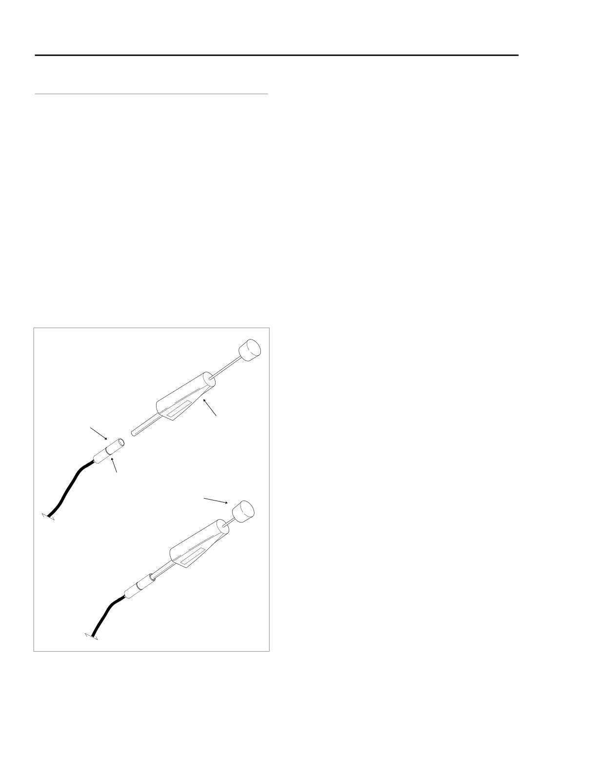
Fit the barrel of the Amp Socket Terminal Remover (HD-
2.
Push the lead into the socket housing until it stops. A
39621-27) over the socket, and while rotating the tool
click is heard when the terminal is properly seated.
slightly, push until it bottoms in the housing. Allow the
plunger to “back out” of the handle. See Figure 8-58.
3.
Gently tug on the lead to verify that the terminal is locked
in place.
4.
Push the pin and socket halves of the connector
together until the latches “click.”
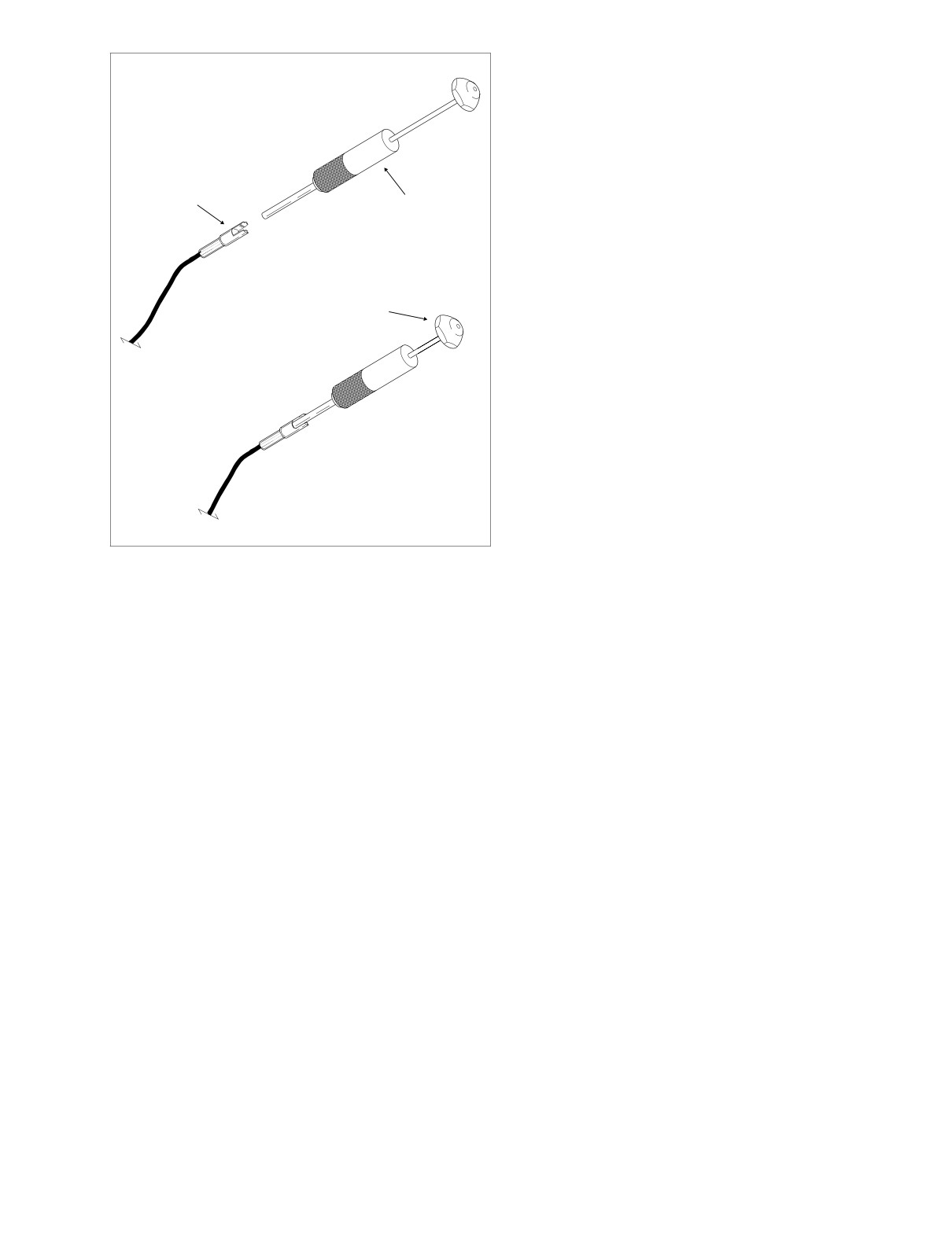
A
Install Socket Terminal Remover
Pin Terminal
Removal
Socket
1.
Bend back the ears on the pin housing slightly and sepa-
Housing
Amp Socket
rate the pin and socket halves of the connector.
Terminal Remover
(HD-39621-27)
2.
Grasp the lead on the wire end of the pin housing and
push the terminal forward toward the mating end of the
connector until it stops. This will disengage the locking
Lip
tang from the groove in the connector.
Plunger
3.
Fit the barrel of the Amp Pin Terminal Remover (HD-
39621-28) over the pin, and while rotating the tool
slightly, push until it bottoms in the housing. Allow the
plunger to “back out” of the handle. See Figure 8-59.
4.
Holding the pin housing while keeping the tool firmly bot-
tomed, depress the plunger. The terminal pops out the
B
Depress Plunger
wire end of the connector.
NOTE
If the terminal is not released from the pin housing, then the
terminal was not pushed forward far enough before place-
ment of the tool or the tool was not bottomed in the connector
f1364x8x
housing.
Figure 8-58. Remove Terminal from Amp Socket Housing
8-40
2005 Touring: Wiring
HOME
Installation
A
Install Pin Terminal Remover
1.
Push the lead into the pin housing until it stops. A click is
heard when the terminal is properly seated.
2.
Gently tug on the lead to verify that the terminal is locked
in place.
Pin
3.
Push the pin and socket halves of the connector
Housing
together until the latches “click.”
Amp Pin
Terminal Remover
(HD-39621-28)
Plunger
B Depress Plunger
f1366x8x
Figure 8-59. Remove Terminal from Amp Pin Housing
2005 Touring: Wiring
8-41
HOME
NOTES
8-42
2005 Touring: Wiring
HOME
WIRING DIAGRAMS
8.8
SUBJECT
PAGE NO.
FLHT, FLHTC, FLHTCU
Main Harness
8-45
Interconnect Harness
8-47
Ignition Harness (Carbureted)
8-49
Electronic Fuel Injection (EFI) Harness
8-49
Ignition Switch
8-51
Tail Lamp, Auxiliary Lamps, Fender Tip Lamps, Directional Lamps
and Tour-Pak Lights
8-51
Starting and Charging
8-53
Handlebar Controls and Indicator Lamps
8-55
Fairing Cap Switches
8-55
Radio, CB/Intercom and Rear Speakers
8-57
FLTR
Main Harness
8-45
Interconnect Harness
8-47
Ignition Harness (Carbureted)
8-49
Electronic Fuel Injection (EFI) Harness
8-49
Ignition Switch
8-51
Tail Lamp and Directional Lamps
8-51
Starting and Charging
8-53
Handlebar Controls and Indicator Lamps
8-55
Instrument Nacelle Switches
8-55
Radio
8-57
FLHR, FLHRC, FLHRS
Main Harness
8-59
Ignition Harness (Carbureted)
8-61
Electronic Fuel Injection (EFI) Harness
8-61
Starting and Charging
8-63
Handlebar Controls, Speedometer, Indicator Lamps, Tail Lamp, Auxiliary Lamps,
Directional Lamps, Fender Tip Lamps and Spot/Accessory Switches
8-65
TLE Sidecar, TLE Ultra Sidecar
Chassis
8-67
Audio Harness
8-67
NOTE
Harness Part No.’s may be included on some wiring diagrams. Use these numbers for reference only.
ALWAYS REFER TO THE PARTS CATALOG WHEN ORDERING WIRING HARNESSES.
2005 Touring: Wiring
8-43
HOME
NOTES
8-44
2005 Touring: Wiring
HOME
CARBURETED ONLY
TSM/TSSM
EFI
40A
BATTERY
1
BN/GY
IGNITION
2
GY
FUEL LEVEL
OPTIONAL
MAXI-FUSE
TO
VSS/SERIAL DATA LINK
3
LGN/V
SENDER
SECURITY
IGNITION
KEYSWITCH IGN RELAY
SECURITY INDICATOR
4
BN/V
FUEL
SIREN
SWITCH
LEFT TURN FEED
5
V
PUMP
[33B]
RIGHT TURN FEED
6
BN
VOLTAGE
B+
RIGHT TURN SW INPUT
7
W/BN
REGULATOR
CONNECTOR
A B C D
[126A]
LEFT TURN SW INPUT
8
W/V
FUEL PUMP
[141A]
START RELAY CONTROL
9
TN/GN
ASSEMBLY
[142A]
[5B]
A B
[33A]
IGNITION ENABLE
10
IN TANK
1
2
3
85863087A
ALARM SIGNAL
11
LGN/BN
GROUND
12
BK
AT TOP OF TANK
1
2
3
A B C
[77A]
[160B]
[126B]
[141B]
MAIN POWER
[30A]
[30B]
TURN SIGNAL/
[142B]
AT STARTER
TURN SIGNAL SECURITY
(GY)
70369-02
MODULE
FUEL TANK
[13B]
HARNESS
1
2
3
12
BK
[141A]
11
LGN/V
1
2
3
10
O/GY
1 2 3
TO
9
R
[13A]
IGNITION/EFI
8
BK
7
R
HARNESS
6
GY
[8A]
5
W/GN
(GY)
4
3
BE/O
[64B]
2
W/BK
1
BN/GY
O/V
4E
3
RH GND
R/Y
3F
5
[8B]
BK/GN
STUD
BK
BRAKE
R/BE
3E
2
RELAY
- FRAME GROUND -
BK
4F
1
12
11
GN/R
BK
LH GND
BK
W/V
10
STUD
1B
INSTRUMENTS - 15A
1A
W/BN
TO
9
O
R/BK
O/BE
INTERCONNECT
8
BN
1D
LIGHTS - 15A
1C
HARNESS
7
V
BE
6
W/BK
1H
HEADLAMP - 15A
1G
[1A]
5
O/W
BE
R/BK
(BK)
4
O/R
1F
IGNITION - 15A
1E
START RELAY
3
GY
GY
2
O/V
4D
P&A IGN - 2A MAX
4C
1
O
R/BK
[123A]
2B
CRUISE/BRAKE - 15A
2A
[1B]
O/V
R/GY
85863087A
2D
ACCESSORIES - 15A
2C
O/W
12
BK
[123B]
2F
P&A - 15A
2E
11
W/GN
O/R
10
TN
TO
3B
RADIO MEM - 15A
3A
9
GN/Y
INTERCONNECT
R/O
R
8
BN/GN
3D
BATTERY - 15A
3C
HARNESS
7
O
BN/GY
[2A]
6
Y/BK
5
Y/W
RADIO PWR - 10A
(GY)
4B
4A
4
BN/GY
O/BE
O/GN
3
BE
2
BK/R
1
R/BE
[2B]
[128B]
TO
D
BK
INTERCONNECT
C
BK/GN
START
HARNESS
B
BE
[15A]
A
R/O
SOLENOID
[15B]
CRANK POSITION
SENSOR
BK
4
O
3
ACCESSORY
R/Y
2
CONNECTOR
O/R
1
(BK)
BK
2
2
[12B]
[4A]
BK
R
1
1
32 1
(BK - LOCATED UNDER SEAT)
[79A]
[79B]
NEUTRAL
SWITCH
TOUR-PAK
[12A]
BN/GN
GN/Y
[131]
[17B]
THROTTLE
ROLL-OFF
HORN
[75C]
[139B]
SWITCH
D C B A
[7A]
REAR
[17A]
OIL
[75A]
[156A]
1 2
3 4 5 6 7 8
PRESSURE
[75D]
STOPLIGHT
SWITCH
TO REAR
SENDER
6 5
4 3
2 1
O/V
[121]
LIGHTING
[139A]
Y/V
[122 ]
TO INTERCONNECT
[7B]
[75B]
[156B]
f2227z8x
(GY)
CRUISE CONTROL MODULE
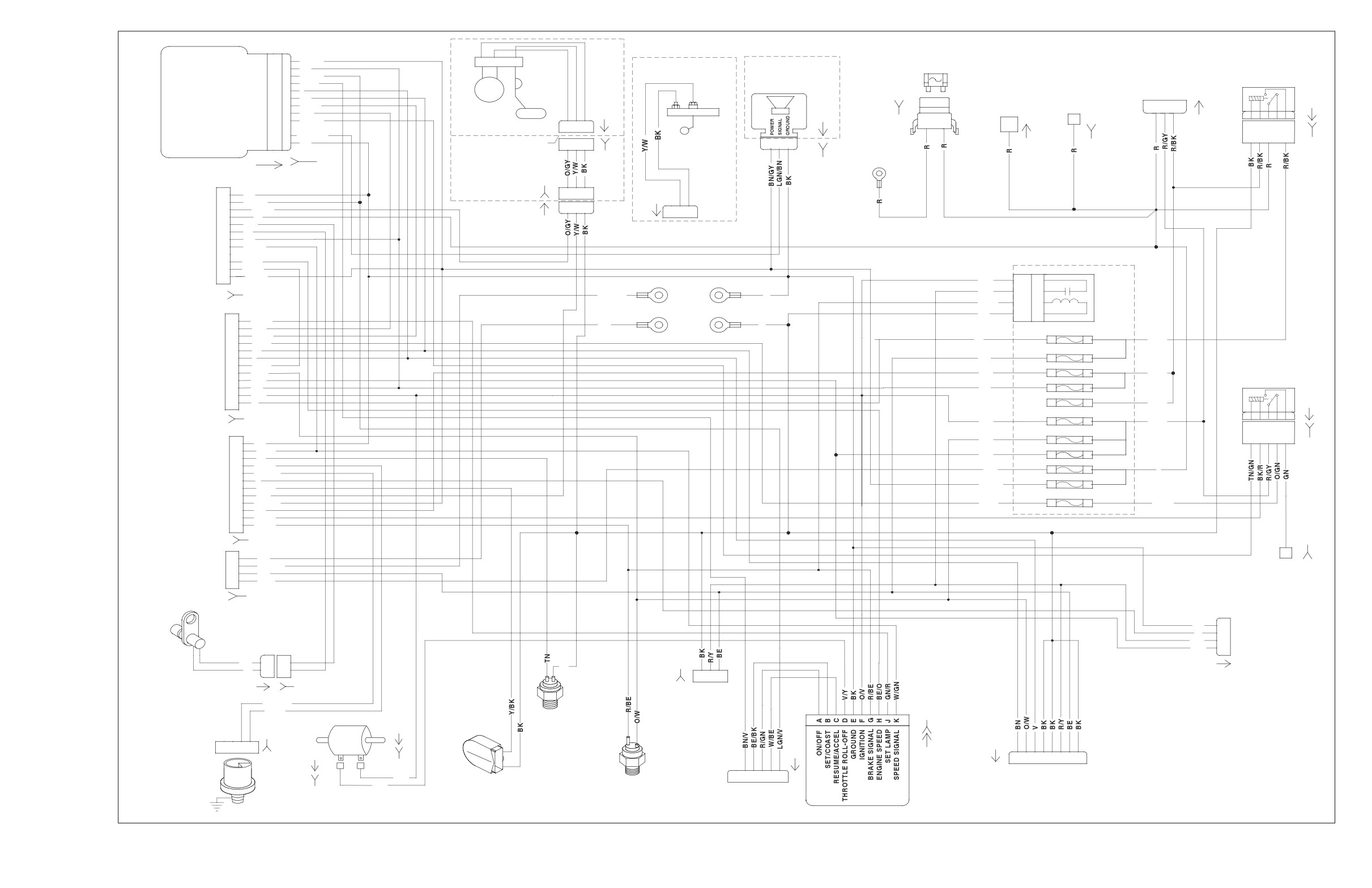
2005 FLHT, FLHTC, FLHTCU and FLTR, DOMESTIC and INTERNATIONAL Models,
Main Harness
8-45
HOME
2005 FLHT, FLHTC, FLHTCU and FLTR
2005 FLHT, FLHTC, FLHTCU and FLTR
DOMESTIC and INTERNATIONAL Models,
DOMESTIC and INTERNATIONAL Models,
Main Harness
Main Harness
8-46
2005 Touring: Wiring
HOME
[21B]
[105B]
NOTE: OIL PRESSURE GAUGE AND AIR TEMP GAUGE
FRONT FENDER
TO DASH PANEL
TO INDICATOR
TIP LAMP
NOT INCLUDED ON FLHT AND FLHTP
2
BK
LAMPS
SWITCHES
[32B]
1
BE
OIL
(BK)
1
2
3
4
5
6
7
8
9
10
1211109
8
7
6
5
4
3
2
1
AIR
FUEL
VOLTMETER
PRESSURE
[32A]
TEMPERATURE
[21A]
[105A]
(BK)
(BK)
[116A]
[116B]
[110A]
[110B]
[112A]
[112B]
[114A]
[114B]
PASSING
2
GY/BK
1
2
1
2
1
2
1
2
[115A]
LAMPS
1
GY/BK
S
[111A]
[113A]
+
S
[117A]
+
+
S
+
S
[73B]
1
3
1
3
1
3
1
3
[73A]
2
2
2
2
(WE)
LO_BEAM
[115B]
[111B]
[113B]
HEADLAMP
[117B]
[38B]
Y
HI_BEAM
W
GND
HDI ONLY
BK
[29B]
BK
(BK)
[107B]
O/W
BE/V
1
2
TEMP SIGNAL
[22A]
GROUND
BK
3
1
O/W
2
AIR
R/BE
3
GY
TEMPERATURE
4
W/BK
TO
SENSOR
5
W/BN
RIGHT HAND
6
[107A]
BK/R
CONTROLS
7
BN/W
[22B]
8
GY/W
(BK)
9
PK/W
10
V/BK
11
W/BE
12
BE/BK
GN/R
12
W/V
11
GROUND
W/BN
10
[GND3]
TO
TO UPPER
O/BE
9
TRIPLE
BK/GN
BN
8
MAIN
BK/GN
V
7
HARNESS
CLAMP
GROUND EXTENDED ON
W/BK
6
(BLACK)
FLTR. P/N 70420-98
O/W
5
[1B]
O/R
4
12
O/BK
GY
3
11
GY/GN
O/V
2
10
GN/BE
O
1
TO
9
PK/W
8
BN/BK
[1A]
LEFT HAND
7
V/BK
CONTROLS
6
Y/BK
[24B]
5
W/V
BK
12
4
W
W/GN
11
(GY)
3
BE
TN
10
TO
2
Y
GN/Y
9
1
O/W
BN/GN
8
MAIN
O
7
HARNESS
[24A]
Y/BK
6
(GRAY)
Y/W
5
[2B]
[27B]
BN/GY
4
BE
3
1
LGN/BK
BK/R
2
2
BE/Y
R/BE
1
3
PK/W
4
GY/W
[2A]
5
V/BK
6
BN/W
TO
7
BK
D
O/BK
MAIN
8
BK/GN
C
BN/BK
HARNESS
9
W/GN
BE
B
R/O
A
[15B]
TO
10
R/O
11
BK/GN
(BK)
RADIO
12
O/BE
[15A]
[27A]
13
BN/O
[39B]
(BK)
14
(BK)
[108B]
15
V/GY
1
2
3
4
5
6
7
8
9 1011 12
(GY)
16
W/O
1
23
4
56
7
8
910 1112
17
LGN/W
18
GY/R
O/W
19
BK/GN
CIGAR
20
R/O
BK
LIGHTER
21
V/O
[132B]
22
GY/GN
23
GN/BE
RIGHT
[34B]
[6B]
[156B]
FRONT
[31R]
[31L]
SPEAKER
[31A]
RPM x 100
LGN/BK
(EXCEPT FLHT)
GY/R
A B C
1
2
3
4
5
6
3
2
1
3
2
1
(BK)
6
5 4
3
2
1
TO MAIN
RH FRONT
LH FRONT
TO AUDIO
TURN SIGNAL
TURN SIGNAL
TURN SIGNALS
ODOMETER
[35B]
HARNESS
RESET
LEFT
HARNESS
FLHT/I, FLHTC/I
[156A]
FLTRI ONLY
SWITCH
[6A]
FLHTCUI ONLY
FRONT
LGN/W
(GY)
SEPARATE CONNECTORS
[154A]
(BK)
FOR FRONT
SINGLE CONNECTOR
SPEAKER
W/O
FOR FRONT
TURN SIGNALS
f2227y8b
(EXCEPT FLHT)
TURN SIGNALS
SPEEDOMETER
TACHOMETER
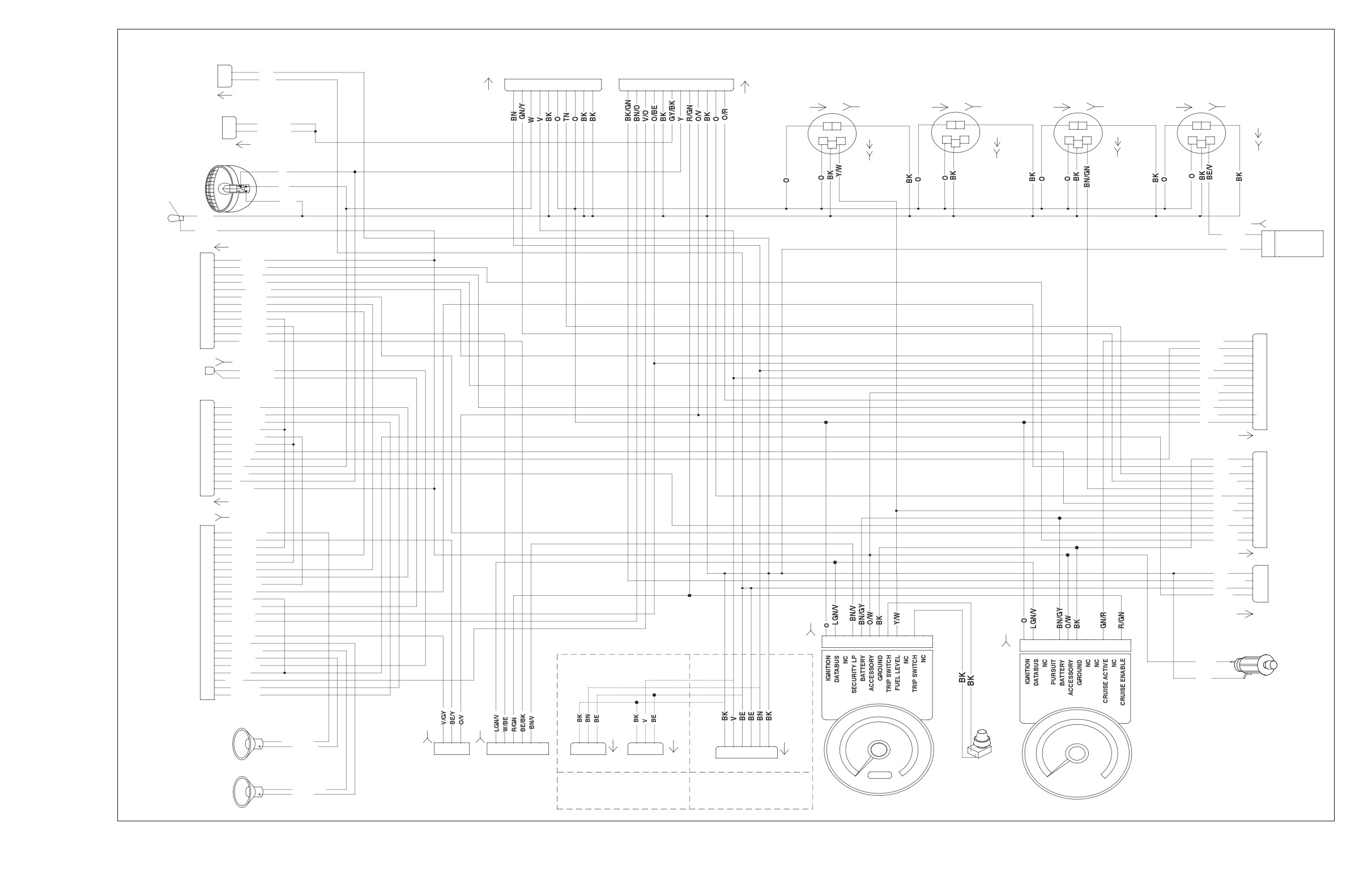
2005 FLHT, FLHTC, FLHTCU and FLTR, DOMESTIC and INTERNATIONAL Models,
Interconnect Harness
8-47
HOME
2005 FLHT, FLHTC, FLHTCU and FLTR
2005 FLHT, FLHTC, FLHTCU and FLTR
DOMESTIC and INTERNATIONAL Models,
DOMESTIC and INTERNATIONAL Models,
Interconnect Harness
Interconnect Harness
8-48
2005 Touring: Wiring
HOME
MAP
DATA
IGNITION
SENSOR
C B A
LINK
COIL
+5V DC
CARBURETED
(GY)
1234
CB A
R/W
A
A
R
IGNITION
W/GN
B
B
W
COIL
VEHICLES
[91A]
[83B]
[80A]
[83A]
BK
C
C
BK
(CARB)
OUTPUT
[65B]
SENSOR
GROUND
C B A
(BK)
[65A]
IGNITION CONTROL MODULE
VEHICLE
[80B]
SPEED SENSOR
(BLK)
[BLK]
[10A]
[10B]
BK
12
RUN/STOP SIGNAL
1
ABCD
[83A]
1
W/BK
LGN/V
11
BATTERY
2
10
2
BN/GY
FRONT SPARK
IGNITION
+5V SENSOR PWR
3
R/W
9
FROM
REAR SPARK PLUG
COIL
3
PLUG
SENSOR GROUND
4
BK/W
BK
8
4
MAIN
(EFI)
MODULE GROUND
5
BK
R
7
5
HARNESS
COIL FRONT
6
BE/O
GY
6
6
[8B]
COIL REAR
7
Y/BE
W/GN
5
7
CRANK SENSOR (+)
8
8
R
4
9
BK
BE/O
3
CRANK SENSOR (-)
9
10
W/GN
W/BK
2
VEHICLE SPD SIG
10
11
V/W
BN/GY
1
MAP SIGNAL
11
+5V DC
12
12
LGN/V
DATALINK
[8A]
R/W
A
A
R
W/GN
B
B
W
(GY)
BK
C
C
BK
OUTPUT
[65B]
SENSOR
(BK)
[65A]
GROUND
CARBURETED OVERLAY: 32435-04
VEHICLE
EFI OVERLAY: 70233-04
SPEED SENSOR
REAR
FRONT
INTAKE
ENGINE
INJECTOR
INJECTOR
AIR
IDLE AIR
TEMP.
TEMP.
CONTROL ACTUATOR
SENSOR
SENSOR
THROTTLE
MAP
BK
12
POSITION
LGN/V
11
FUEL INJECTED
SENSOR
SENSOR
O/GY
10
R
9
FROM
VEHICLES
DATA
IGNITION
BK
8
R
MAIN
LINK
COIL
7
(GY)
GY
6
HARNESS
1
2
3
4
AB
AB
ABCD
W/GN
5
[8B]
[91A]
4
ELECTRONIC
DCB A
PK
3
(GY)
[83B]
AB
AB
CB A
CBA
[87B]
CONTROL
[90B]
[89B]
W/BK
2
MODULE
[85B]
1
[84B]
[88B]
[80B]
[78A]
[78B]
[8A]
ALDL & FLASH PIN
LGN/R
CHECK ENG LP
TACH OUTPUT
PK
SYSTEM RELAY
GN/O
SERIAL DATA LINK
LGN/V
ENGINE TEMPERATURE
PK/Y
INTAKE AIR TEMPERATURE
LGN/Y
OXYGEN SENSOR A
ANALOG INPUT
POWER GROUND
BK
COIL REAR
Y/BE
[119B]
CRANK POS. SENSOR (-)
BK+
SWITCH POWER
W/BK
FUEL PUMP 15A
5V SENSOR POWER
R/W
G
H
DIGITAL GROUND
O/GY
Y/GN
FREQUENCY INPUT
IDLE AIR CNTL MOTOR
BK/O
ECM POWER 15A
IDLE AIR CNTL MOTOR
BK/PK
A
B
INJECTOR REAR
GN/GY
BE/GY
R
OUTPUT (unused)
INJECTOR FRONT
W/Y
SYSTEM RELAY
(BK)
OUTPUT (UNUSED)
OXYGEN SENSOR B
Y/GN
K
5
THROTTLE POS SNSR INPUT
GY/V
T
4
MAP SENSOR INPUT
V/W
BE/GY
E
3
5V SENSOR GROUND
BK/W
GN/O
S
2
ION SENSE
GY/BE
W/BK
U
1
POWER GROUND
BK
COIL FRONT
BE/O
CRANK POS. SNSR (+)
R
CONSTANT POWER
BE/GY
SWITCH INPUT (unused)
VEHICLE SPEED INPUT
W/GN
DIGITAL POWER
IDLE AIR CNTL MOTOR
BE/GN
IDLE AIR CNTL MOTOR
BN/R
f2227x8x
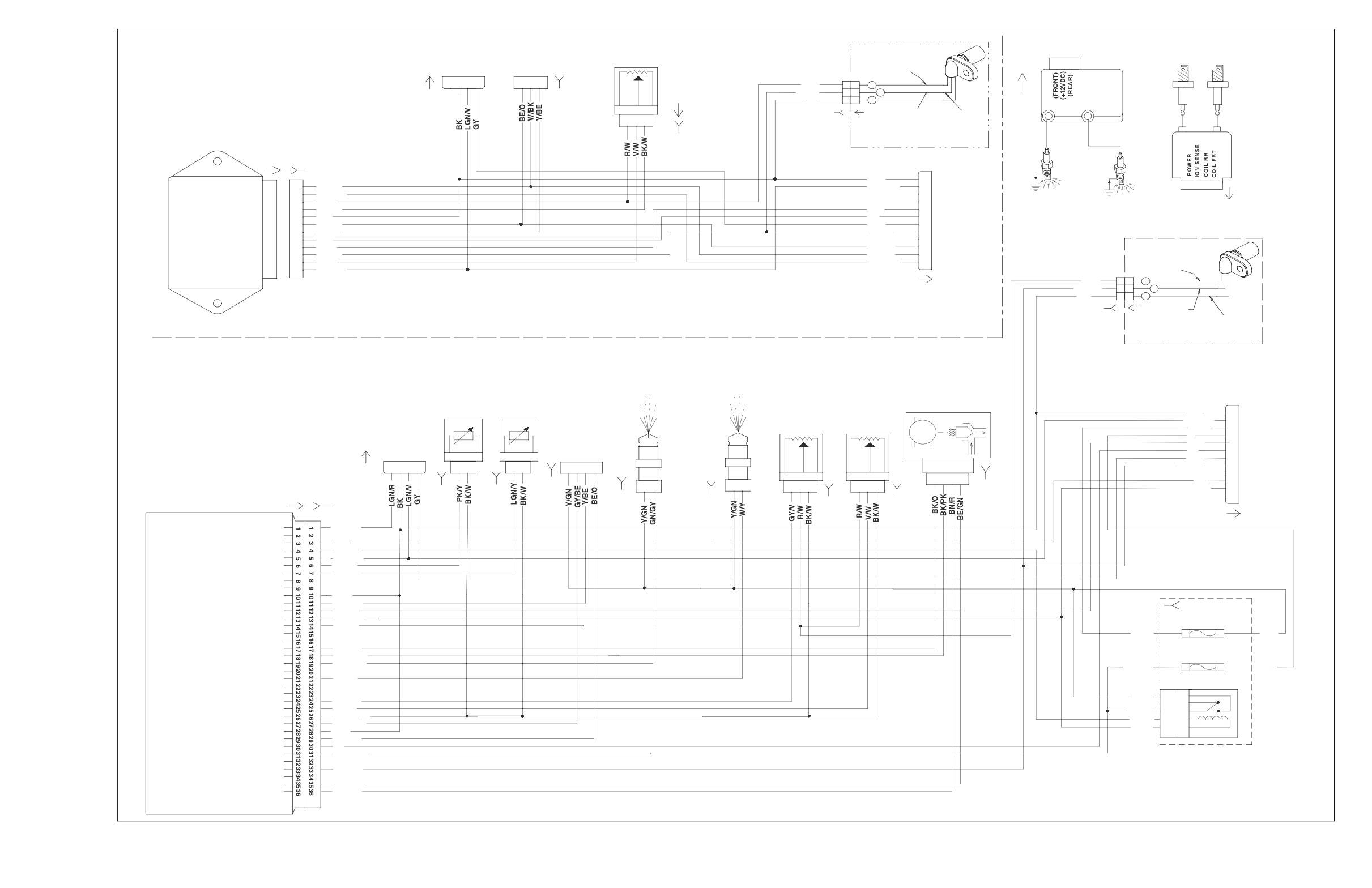
2005 FLHT, FLHTC, FLHTCU and FLTR, DOMESTIC and INTERNATIONAL Models,
Ignition Harness (Carbureted), Electronic Fuel Injection (EFI) Harness
8-49
HOME
2005 FLHT, FLHTC, FLHTCU and FLTR
2005 FLHT, FLHTC, FLHTCU and FLTR
DOMESTIC and INTERNATIONAL Models,
DOMESTIC and INTERNATIONAL Models,
Ignition Harness (Carbureted),
Ignition Harness (Carbureted),
Electronic Fuel Injection (EFI) Harness
Electronic Fuel Injection (EFI) Harness
8-50
2005 Touring: Wiring
HOME
1 2
3 456 78
FROM MAIN
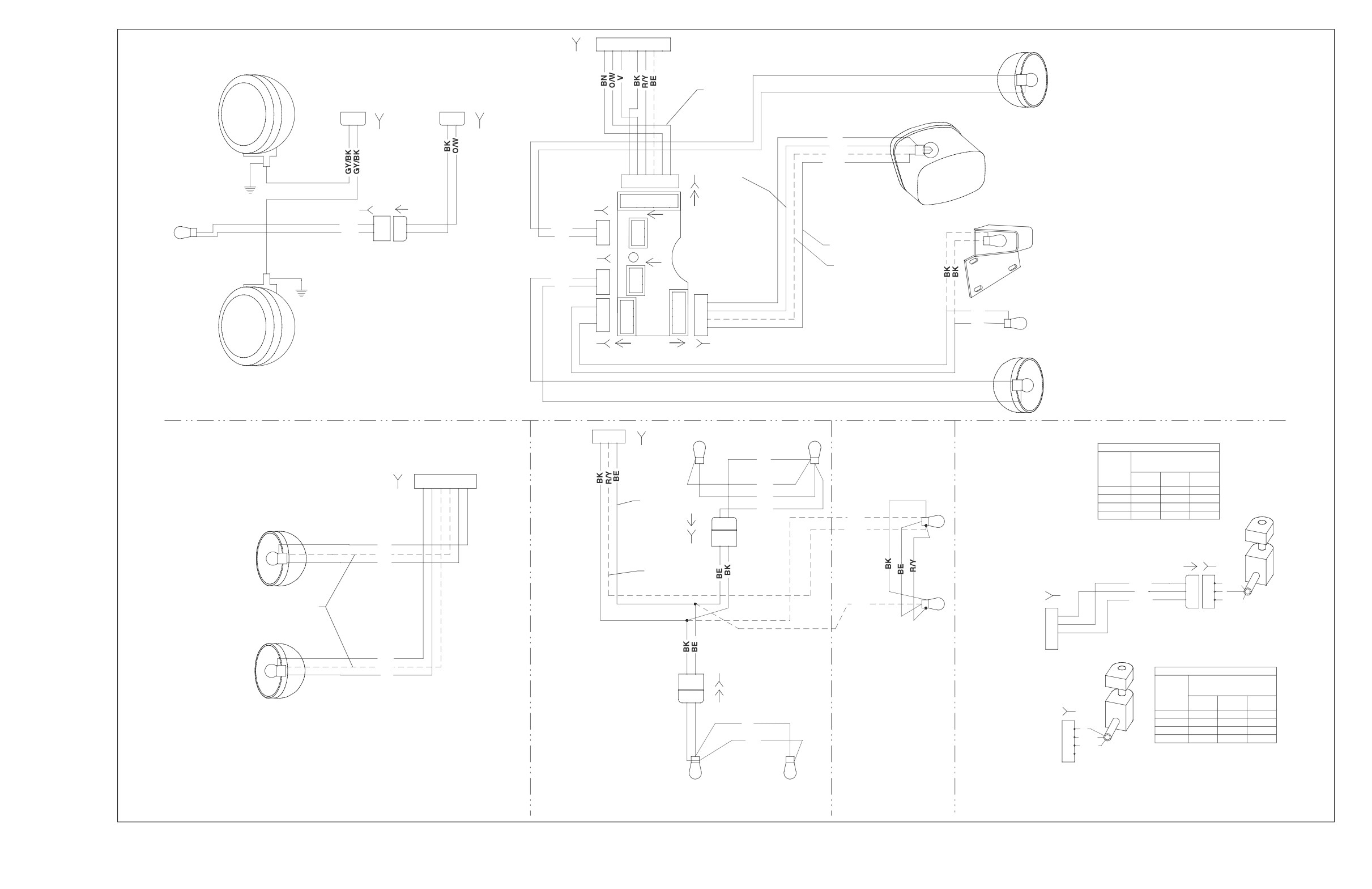
REAR LIGHTING
HARNESS [7A]
[7B]
RIGHT PURSUIT
LAMP (BLUE)
RIGHT REAR
POLICE ONLY
FROM
FROM
DIRECTIONAL
INTERCONNECT
INTERCONNECT
68772-99
LAMP
HARNESS [73A]
HARNESS [32A]
RIGHT
AUXILIARY
2 1
2 1
LAMP
[73B]
[32B]
BK
TAILLAMP
R/Y
O/W
BEW
[94B] BRAKE LIGHT
654 3
2
1
654 3
2
1
FENDER TIP LAMP
[143B]
[143A]
[19b]
[94A]
(DOM ONLY)
[19a]
O/W
1
1
V/BN
1
1
BK
2
2
BK
2
2
RUNNING LIGHT (DOM)
LICENSE
[18a]
[18B]
PLATE LAMP
RUNNING LIGHT (HDI)
(HDI ONLY)
V/BN
1
1
BK
2
2
4
4
1
1
3
3
BK
2
2
2
LEFT
2
FENDER TIP LAMP
3
3
1
BK
AUXILIARY
1
(DOMESTIC ONLY)
LAMP
[93B]
[45B]
[45A]
[93A]
LEFT PURSUIT
LAMP (RED)
LEFT REAR
POLICE ONLY
DIRECTION
LAMP
3
2
1
TOUR-PAK RIGHT SIDE
ULTRA TOUR-PAK
TO MAIN
MARKER LIGHTS
IGNITION SWITCH LEGEND (HDI)
FROM
[12B]
REAR MARKER/
INTERCONNECT
HARNESS
"X" INDICATES CONTINUITY
BK
STOP LIGHTS
BETWEEN LEAD WIRES
HARNESS [31A]
[12A]
SWITCH
IN POSITION INDICATED
POSITION
RED/
RED/
6
5
4
3
2
1
RED
GRAY
BLACK
BK
LOCK
X
[31B]
BE
OFF
X
TAIL
IGN
X
X
X
[12-2A]
BE
BK
ACC
X
X
1 2
R/Y
RIGHT
1 2
BK
DIRECTIONAL
[12-2B]
BE
AND DOM
BN
RUNNING LAMP
STOP
R/GY
1
1
R/GY
[33B - HDI]
R
2
2
R
R/BK
3
3
R/BK
BLUE WIRES (RUNNING) ARE ONLY
BE
IGNITION
AVAILABLE ON DOMESTIC MODELS
A
FROM MAIN
SWITCH,HDI
B
HARNESS [33A]
C
D
DOM TOUR-PAK HARNESS:
NOTE:
LEFT
FLHTC P/N
DOM FLHTC
BK
DIRECTIONAL
BE
70646-00
DOES NOT INCLUDE
[12-3B]
IGNITION SWITCH LEGEND (DOM)
AND DOM
V
FLHTC-U
REAR MARKER/STOP
2
1
"X" INDICATES CONTINUITY
RUNNING LAMP
FLHTCU-I
LIGHTS AND
BETWEEN LEAD WIRES
SWITCH
IN POSITION INDICATED
P/N 70648-00
2
1
ASSOCIATED WIRING
POSITION
[ 33B-DOM]
RED
RED/
RED/
GRAY
BLACK
[12-3A]
LOCK
X
BE
OFF
X
FROM MAIN
A
R
IGN
X
X
X
B
R/GY
ACC
X
X
TOUR-PAK LEFT SIDE
BK
HARNESS [33A]
C
R/BK
MARKER LIGHTS
D
IGNITION
SWITCH,DOM
HDI FLHTC AND FLHTCU MODELS DO NOT HAVE TOUR-PAK LIGHTING
TOUR-PAK NOT INCLUDED ON FLHT OR FLHTP
f2227u8b
2005 FLHT, FLHTC, FLHTCU and FLTR, DOMESTIC and INTERNATIONAL Models,
Ignition Switch, Tail Lamp, Auxiliary Lamps, Fender Tip Lamps, Directional Lamps and Tour-Pak Lights
8-51
HOME
2005 FLHT, FLHTC, FLHTCU and FLTR
2005 FLHT, FLHTC, FLHTCU and FLTR
DOMESTIC and INTERNATIONAL Models,
DOMESTIC and INTERNATIONAL Models,
Ignition Switch, Tail Lamp,
Ignition Switch, Tail Lamp,
Auxiliary Lamps, Fender Tip Lamps,
Auxiliary Lamps, Fender Tip Lamps,
Directional Lamps and Tour-Pak Lights
Directional Lamps and Tour-Pak Lights
8-52
2005 Touring: Wiring
HOME
STATOR
f2227n8x
[46A]
[46B]
+
BK
A
DC
A
BK
-
AC
TSM/TSSM
BK
B
B
BK
BATTERY
1
BN/GY
IGNITION
2
GY
VSS/SERIAL DATA LINK
3
LGN/V
SECURITY INDICATOR
4
LEFT TURN FEED
5
40 A
RIGHT TURN FEED
6
RIGHT TURN SW INPUT
7
MAXI-FUSE
LEFT TURN SW INPUT
8
START RELAY CONTROL
9
TN/GN
IGNITION ENABLE
10
ALARM SIGNAL
11
GROUND
12
BK
B A
[30A]
[30B]
TURN SIGNAL/
TURN SIGNAL SECURITY
[77B]
[77A]
MODULE
BK
R
R
[8A]
HAND CONTROLS,
RIGHT
1
2
ALL MODELS
3
BK
BK
4
EXCEPT FLHTP
5
6
7
8
9
10
11
LGN/V
12
POWERTRAIN
STARTER
BATTERY
ENGINE OFF/RUN SWITCH
BATTERY
GROUNDS
START SWITCH
BK
BK
CHARGING SYSTEM
40 A
MAXI-FUSE
STARTER
R
[22B]
[22A]
[128B]
[128A]
1
1
2
2
3
3
IGNITION SWITCH LEGEND (HDI)
GY
GY
R
"X" INDICATES CONTINUITY
4
4
BETWEEN LEAD WIRES
5
5
GN
B A
SWITCH
IN POSITION INDICATED
6
POSITION
BK/R
6
BK/R
RED
RED/
RED/
7
7
GRAY
BLACK
8
8
BK
LOCK
X
9
9
OFF
X
TO INTERCONNECT
10
10
TO
IGN
X
X
X
HARNESS
11
11
RIGHT-HAND
ACC
X
X
12
TO
TO
[22A]
12
CONTROL
MAIN
INTERCONNECT
[22B]
HARNESS
HARNESS
[1A]
[33D] [33C]
[1B]
(BLACK)
[33B]
RIGHT
LEFT
12
12
BK
GND2
GND1
R/BK
86
1
MAIN FUSE BLOCK COVER
11
11
BK
85
A
R
2
10
10
R
30
B
R/GY
3
10A
9
9
87A
C
R/BK
8
8
7
[64]
87
D
IGNITION
15A
P&A IGN RADIO PWR
7
JUMPER HARNESS
6
6
BATTERY
[126B]
[126A]
SWITCH, HDI
BRAKE
5
3D
3C
15A
5
FROM MAIN
RELAY
4
4
BN/GY
R
BATTERY RADIO MEM
3
GY
HARNESS [33A]
GY
3
KEY SWITCH IGN RELAY
2
2
SPARE FUSES
1
1
P&A
ACCESS.
CRUISE/BRK
[33A]
[1A]
[1B]
(BK)
R
A
TO
HEADLAMPS IGN
LIGHTS
INSTRUMENTS
IGNITION
12
12
1F
1E
R/GY
B
IGNITION
11
11
GY
R/BK
R/BK
C
SWITCH
[33B]
10
10
D
[33B]
9
9
8
8
A
R
7
7
START RELAY
6
B
R/GY
6
5
FROM MAIN
C
R/BK
10A
5
TN/GN
85
D
BRAKE
4
4
HARNESS [33A]
3
BK/R
86
RELAY
15A
15A
3
30
IGNITION
BK/R
2
BK/R
R/GY
2
1
87A
SWITCH, DOM
1
(GY)
GN
87
15A
15A
15A
[2A]
(GRAY)
[2B]
IGNITION SWITCH LEGEND (DOM)
"X" INDICATES CONTINUITY
15A
15A
15A
15A
SWITCH
BETWEEN LEAD WIRES
TO
TO
POSITION
IN POSITION INDICATED
[123B]
[123A]
RED/
RED/
MAIN
INTERCONNECT
RED
GRAY
BLACK
HARNESS
HARNESS
LOCK
X
[2B]
(2A)
OFF
X
MAIN FUSE BLOCK
IGN
X
X
X
ACC
X
X
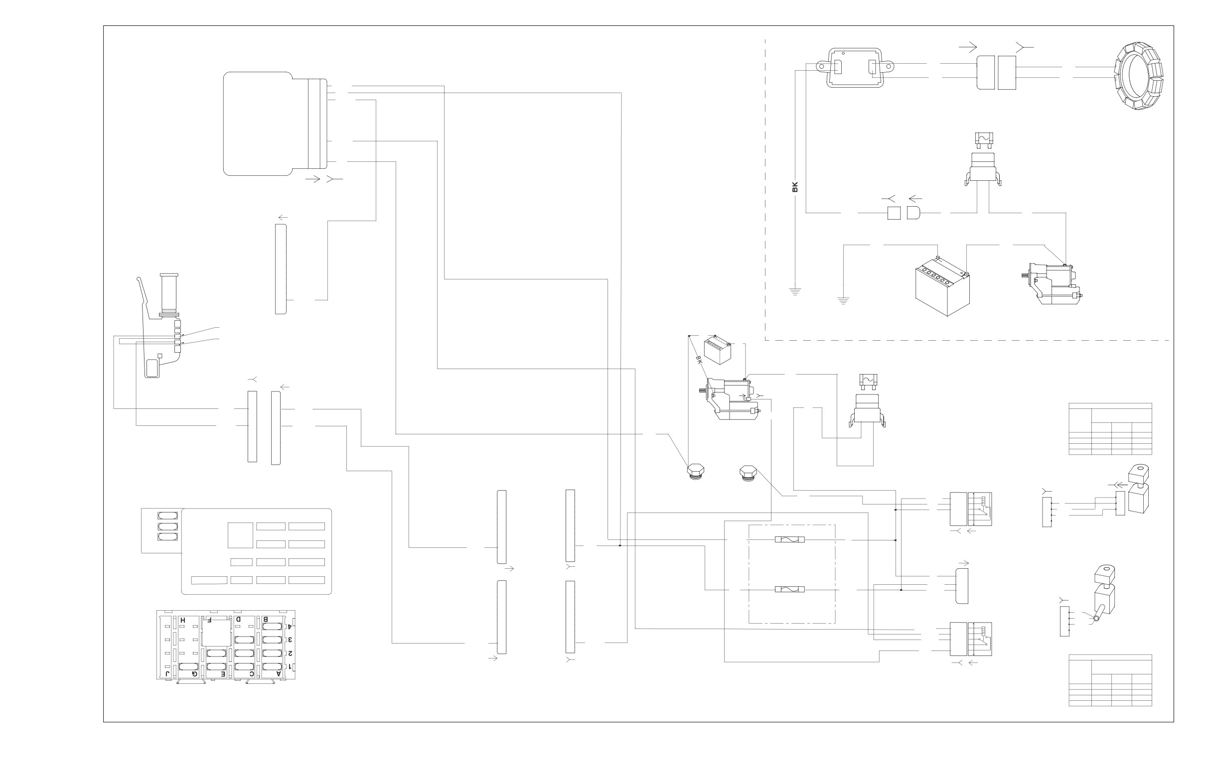
2005 FLHT, FLHTC, FLHTCU and FLTR, DOMESTIC and INTERNATIONAL Models,
Starting and Charging
8-53
HOME
2005 FLHT, FLHTC, FLHTCU and FLTR
2005 FLHT, FLHTC, FLHTCU and FLTR
DOMESTIC and INTERNATIONAL Models,
DOMESTIC and INTERNATIONAL Models,
Starting and Charging
Starting and Charging
8-54
2005 Touring: Wiring
HOME
SWITCH
BROWN/
PINK/
VIOLET/
GRAY/
HAND CONTROLS
POSITION
WHITE
WHITE
BLACK
WHITE
RIGHT
UP
X
X
MODE
X
X
ALL MODELS
DOWN
X
X
EXCEPT
FLHTP
RADIO FUNCTION SWITCH
LEFT
HIGH
RIGHT
TURN
BEAM
NEUTRAL
OIL
TURN
RIGHT DIRECTIONAL SWITCH
ENGINE OFF/RUN SWITCH
START SWITCH
BK
V
HB
BK TN
+
GN/Y
+ RT
BK
CRUISE SET/RESUME SWITCH
-
LT W
- N
O
OP
O
BN
-
(ULTRA MODELS ONLY)
SWITCH
BLUE/
ORANGE/
WHITE/
POSITION
BLACK
WHITE
BLUE
SET
X
X
RESUME
X
X
[21B]
STOP LAMP SWITCH
1 2 3 4 5 6 7 8 9 10
[22B]
TO INTERCONNECT
O/W
1
HARNESS
R/BE
2
[21A]
GY
3
W/BK
4
W/BN
5
TO INTERCONNECT
BK/R
6
BN/W
7
HARNESS
GY/W
8
[22A]
PK/W
9
V/BK
10
W/BE
11
BE/BK
12
O/BK
12
DASH PANEL MOUNTED SWITCHES
GY/GN
11
NOT INCLUDED ON FLHTP-FRG
GN/BE
10
"CRUISE" & "SPEAKER" SWITCHES
PK/W
9
BN/BK
8
TO INTERCONNECT
NOT USED ON FLTR
NOT INCLUDED ON FLHT, FLHTC, OR FLHTC-I
V/BK
7
HARNESS
Y/BK
6
W/V
5
[24A]
SPOT
SPEAKER
CRUISE
ACCY
W
4
BE
3
Y
2
O/W
1
[24B]
4
4
3
3
SWITCH
VIOLET/
GRAY/
ORANGE/
BROWN/
2
2
POSITION
BLACK
GREEN
BLACK
BLACK
+SQ UP (FORE)
X
X
1
1
PTT (PUSH)
X
X
-SQ DN (AFT)
X
X
[105C]
[105D]
PTT & SQ
(PUSH TO TALK & SQUELSCH)
(ULTRA MODELS ONLY)
CONNECTOR ONLY ON FLTR
HORN SWITCH
HEADLAMP HI/LO SWITCH
LEFT DIRECTIONAL SWITCH
LEFT
RADIO AUDIO CONTROL
HAND CONTROLS
SWITCH
PINK/
GREEN/
BROWN/
GRAY/
ALL MODELS
POSITION
WHITE
BLUE
BLACK
GREEN
[105B]
+VOL
X
X
EXCEPT
AUDIO
X
X
1211109 8 7 6 5 4 3
2
1
FLHTP
-VOL
X
X
TO INTERCONNECT
HARNESS
[105A]
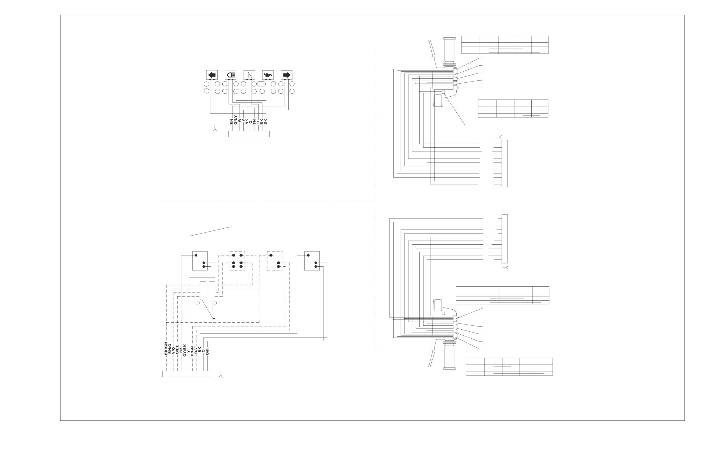
f2227w8x
2005 FLHT, FLHTC, FLHTCU and FLTR, DOMESTIC and INTERNATIONAL Models,
Handlebar Controls, Indicator Lamps and Fairing Cap/Instrument Nacelle Switches
8-55