Harley Davidson 2005 touring models. Service repair manual - page 56

HOME
Test 6.12 (Part 3 of 3)
SIDECAR PTT INOPERATIVE: HARDWARE DIAGNOSIS
What Did Test 6.12 (Part 1 of 3)
Indicate?
SHORT to VOLTAGE
SHORT to GROUND
Disconnect Connector [41B] and
4
Disconnect Connector [41B] and
4
[41C]. With Key ON, Check for Power
[41C]. With Key OFF, Check for Con-
at Connector [41C].
tinuity to Ground at Connector [41C].
To
To
From
From
Terminal
Terminal
(-)
(-)
(+)
(+)
3 (V/BK)
3 (V/BK)
Ground
Ground
4 (O/BK)
4 (O/BK)
Is Voltage Present?
Any Continuity Present?
YES
NO
YES
NO
Replace or
Go to Test 6.12
OPEN
1
Reconnect Connector [41].
Locate and
(Part 2 of 3).
Remove Outer Fairing. Connect
Repair Short to
Breakout Box leaving Connector
Ground in
With Sidecar PTT Switch Depressed,
[28B] Disconnected from Radio.
Sidecar Audio
Check for Continuity at Connector [41C].
Check for Voltage at Terminals 12
Harness.
(O/BK) and 14 (V/BK) of Connec-
Switch
From
To
6940
tor [28B]. Is Voltage Present?
Position
Terminal
Terminal
PTT
4 (O/BK)
3 (V/BK)
Resistance Should be Less than 0.5
YES
NO
Ohms While Switch is Depressed and
Infinity While Switch is Open. Is It?
2
Locate and
Replace
Repair Short To
Radio.
Voltage or
YES
NO
6601
Replace Audio
Harness.
2
Replace
Remove Sidecar Speaker Console. Disconnect
3
6561
Radio.
Connector [149] from Sidecar Speaker Amplifier.
Check Continuity as Follows:
4
6601
FROM
TO
Connector
Terminal
Terminal
Connector
16
4 (O/BK)
[149B]
[42C]
22
3 (V/BK)
At some point in the Software flow chart you may be instructed
to jump directly to the box marked by the asterisk. Disregard the
Continuity Present?
*
asterisk (but not the instruction box) if your normal progression
through the chart brings you to this location.
YES
NO
Replace
Locate and
Sidecar
Repair Open or
Amplifier.
Replace Sidecar
Audio Harness.
6949
6940
After correction of problem, refer to SETUP and
FUNCTIONALITY to verify proper operation.
6-34
2005 Touring: Sound System
HOME
NOTES
2005 Touring: Sound System
6-35
HOME
RADIO SYMPTOM 10
6.13
GENERAL
Functionality
Problem
Speak into Intercom. Voice should be heard in all headsets. Is
it?
Intercom inoperative.
● Yes - System is OK.
● No - See Test 6.13.
Setup
● Press the POWER button to turn the radio ON.
● Set fairing mounted Headset/Speaker Switch to HEAD-
DIAGNOSTICS
SET.
● Press and hold the CB button to turn the Citizen Band
See Test 6.13 on the next page.
radio OFF.
● Press and hold the INT button to turn the Intercom ON
(Setup Mode).
● Use Mode Select Switch to adjust VOX sensitivity to a
value greater than “10.”
● Set Front and Rear Volume Control to Middle position on
horizontal bar graph display.
Not Applicable to Classic/Road Glide Models
10=Headset
11=Speaker
0=PTT
0 or 1
1=Break
1=ON
1=ON
01=Center
AVC
HAND-
CB
INTERCOM
CB
SPEAKER
SPEAKER
VEHICLE
VOX
HELD MIC.
SQUELCH
OFF/ON
OFF/ON
SWITCH
SWITCH
SPEED
BREAK
PTT
BREAK
SWITCH
SWITCH
“B”
“A”
SIGNAL
7
6
5
4
3
2
1
0
(BE/Y)
(W/GN)
Internal
Internal
Internal
Internal
(BN/O)
(V/O)
Figure 6-24. Diagnostic Mode Group 2 Matrix
6-36
2005 Touring: Sound System
HOME
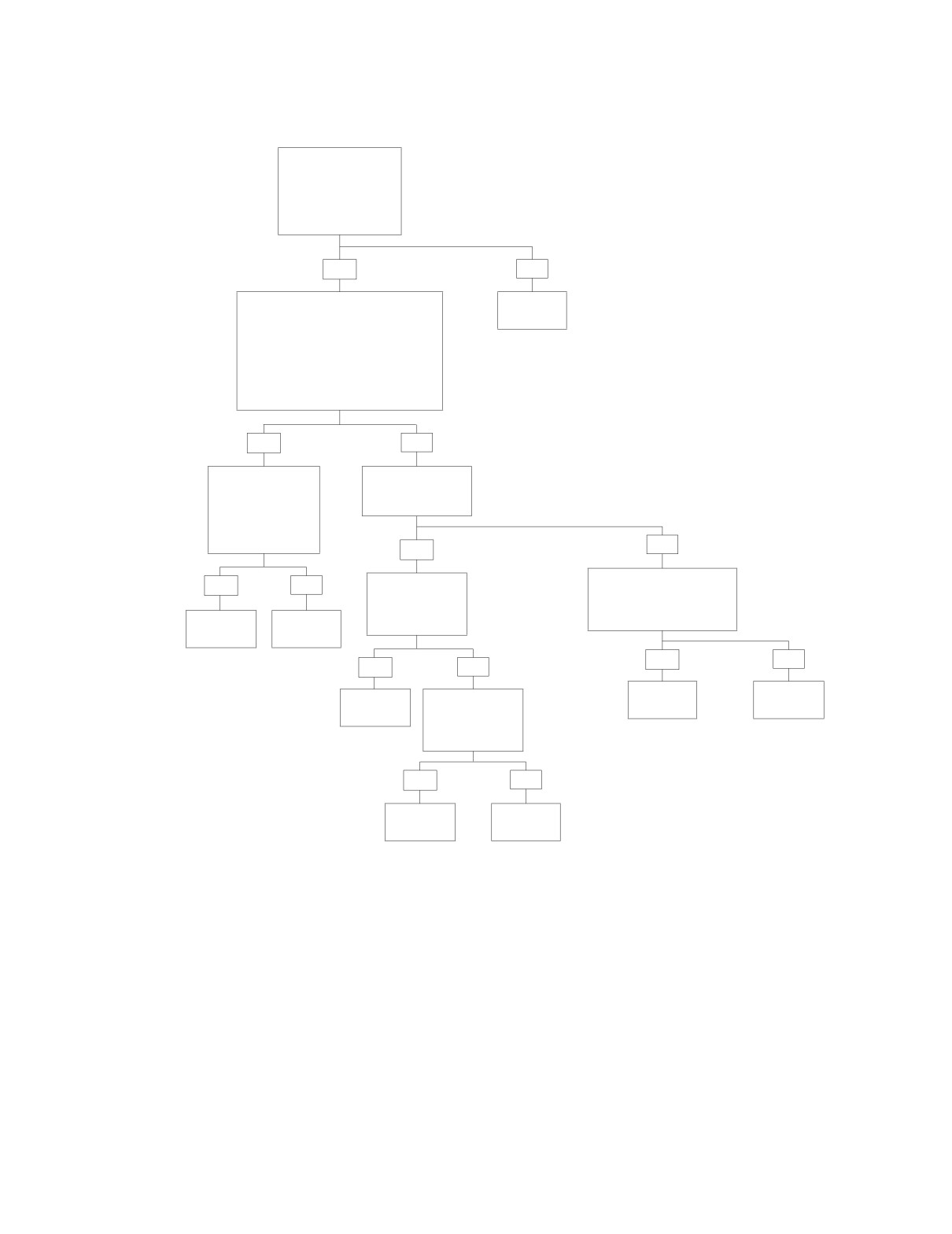
Test 6.13
INTERCOM INOPERATIVE: SOFTWARE DIAGNOSIS
Did Radio Enter
Intercom Setup
Mode as Indicated
by LCD When Inter-
com Switch Turned
On?
YES
NO
Press Mode Up Switch So That VOX
Replace
Level is at Maximum Value (13).
Radio.
Set Front Volume to Middle Position
6601
in Horizontal Bar Graph Display. Set
Rear Volume to Middle Position.
Is Intercom Audio Present When
Speaking Into Microphone
(Both Directions)?
YES
NO
Adjust VOX Level
Is Communica-
to 11. Then Test
tion Possible In
for Audio When
Either Direction?
Speaking Loudly
Into Microphone.
Audio Present?
NO
YES
Verify Headset Operation
YES
NO
Replace
on Another Vehicle.
“Dead” Head-
Do the Speakers and
set. Intercom
Microphone Work?
Intercom
Replace
OK?
OK.
Radio.
6601
YES
NO
YES
NO
Replace
Replace
Intercom
Replace
Radio.
Headset.
OK.
“Dead” Micro-
phone. Inter-
6601
com OK?
YES
NO
Intercom
Replace
OK.
Radio.
6601
After correction of problem, refer to SETUP and
FUNCTIONALITY to verify proper operation.
2005 Touring: Sound System
6-37
HOME
RADIO SYMPTOM 11
6.14
GENERAL
CB OFF/ON
Switch
Problem
CB receiver inoperative.
Setup
● Press the POWER button to turn the
radio ON.
f2122x8x
● Press and hold the INT button to turn the Intercom OFF.
● Set fairing mounted Headset/Speaker Switch to
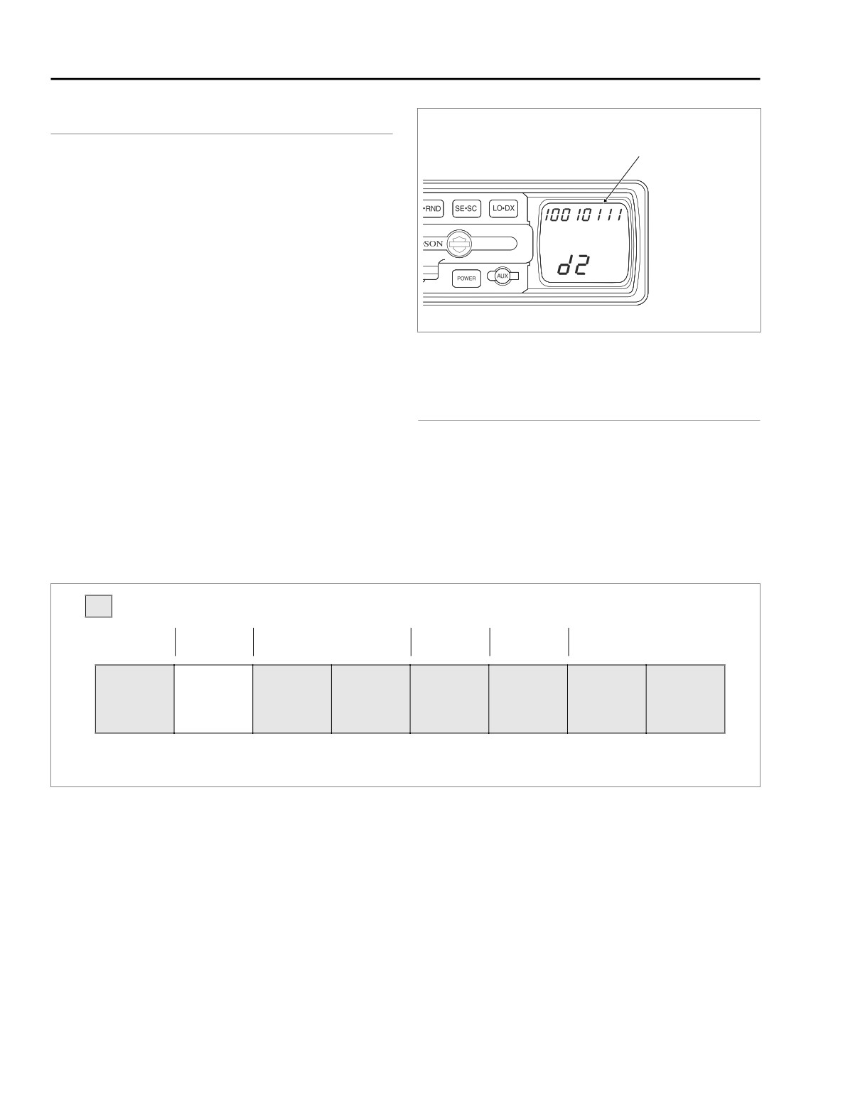
Figure 6-25. LCD Input Bit Display
SPEAKER.
● Set Volume Control to Middle position on horizontal bar
graph display.
DIAGNOSTICS
● Press and hold the CB button to turn the Citizen Band
radio ON.
Diagnostic Notes
The reference number below correlates with the circled num-
Functionality
ber in the Test 6.14 flow chart.
See Test 6.14.
1.
See Section 6.15 RADIO SYMPTOM 12.
Not Applicable to Classic/Road Glide Models
10=Headset
11=Speaker
0=PTT
0 or 1
1=Break
1=ON
1=ON
01=Center
AVC
HAND-
CB
INTERCOM
CB
SPEAKER
SPEAKER
VEHICLE
VOX
HELD MIC.
SQUELCH
OFF/ON
OFF/ON
SWITCH
SWITCH
SPEED
BREAK
PTT
BREAK
SWITCH
SWITCH
“B”
“A”
SIGNAL
7
6
5
4
3
2
1
0
(BE/Y)
(W/GN)
Internal
Internal
Internal
Internal
(BN/O)
(V/O)
Figure 6-26. Diagnostic Mode Group 2
6-38
2005 Touring: Sound System
HOME
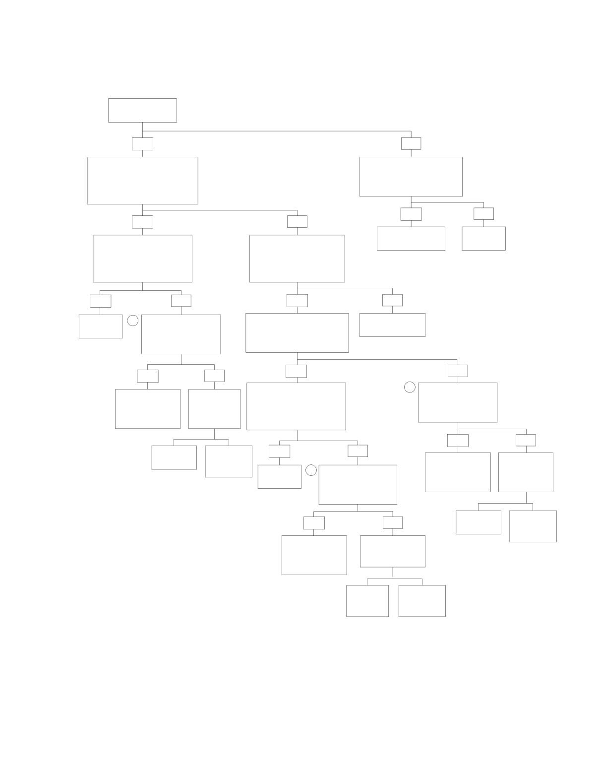
Test 6.14
CB RECEIVER INOPERATIVE: SOFTWARE DIAGNOSIS
Did Radio Enter
CB Setup Mode?
YES
NO
Press SQ- Until Bar Graph
Enter Diagnostics Mode 2.
Moves to Left Most Position.
Does Handheld Microphone
This Forces Squelch Open
PTT Display “0” (i.e., is PTT
Independent of CB Signal
Line Shorted to Ground)?
Strength. Is CB Audio Present?
YES
NO
YES
NO
Go to Test 6.17
Replace
Press SQ+ So Bar Graph
Using Mode Control
(Part 2 of 2).
Radio.
Moves One Bar to the
Switch Press Mode Up or
6601
Right. Is Audio Still Present
Mode Dn to Change CB
(With Test Signal From
Channel. Does Channel
External Transmitter)?
Number Change on LCD?
YES
NO
YES
NO
Receiver
1
Perform Antenna
Using External Transmitter
Go to Test 6.5
OK.
Check and SWR
for Test Signal, Can CB
(Part 2 of 4).
Adjustment Proce-
Audio be Heard When Set to
dures. Antenna OK?
Same Channel as Receiver?
YES
NO
YES
NO
1
Press SQ+ So Bar Graph
Perform Antenna
Bad Squelch
Receiver
Moves One Bar to the
Check and SWR
Circuit Internal
OK. Repair
Right. Is Audio Still Present
Adjustment Proce-
to Radio.
or Adjust
(With Test Signal From
dures. Antenna OK?
Replace Radio.
Antenna.
External Transmitter)?
6601
YES
NO
Replace
Replace
YES
NO
CB Mast.
CB Load
Bad Squelch
Receiver
Coil.
1
Circuit Internal
OK. Repair
6613
Receiver
Perform Antenna
to Radio.
or Adjust
6618
OK.
Check and SWR
Replace Radio.
Antenna.
Adjustment Proce-
dures. Antenna OK?
6601
Replace
Replace
YES
NO
CB Mast.
CB Load
Coil.
6613
Bad Squelch
Receiver OK.
6618
Circuit Internal
Repair or Adjust
to Radio.
Antenna.
After correction of problem, refer to SETUP and
Replace Radio.
FUNCTIONALITY to verify proper operation.
6601
Replace
Replace
CB
CB Load
Mast.
Coil.
6613
6618
2005 Touring: Sound System
6-39
HOME
NOTES
6-40
2005 Touring: Sound System
HOME
RADIO SYMPTOM 12
6.15
● Yes - System is OK.
GENERAL
● No - See Test 6.15 (Part 1 of 2).
Problem
DIAGNOSTICS
CB transmitter inoperative.
Setup
Diagnostic Notes
● Press the POWER button to turn the radio ON.
The reference numbers below correlate with the circled num-
bers in the Test 6.15 flow charts.
● Press and hold the INT button to turn the Intercom OFF.
● Set fairing mounted Headset/Speaker Switch to
1. Remove outer fairing. Disconnect antenna connector
SPEAKER.
from CB and replace it with a dummy load, that is, the
lamp included with tool HD-39448.
● Set Volume Control to Middle position on horizontal bar
graph display.
NOTE
● Press and hold the CB button to turn the Citizen Band
The lamp acts as a load that allows the CB to be operated
radio ON.
and provides a means of checking relative power output and
modulation.
Functionality
2. To use the load, screw the dummy load onto the antenna
jack of the CB. Depress the PTT switch. If the CB is
Depressing any PTT switch will change the radio display to
transmitting a carrier wave, the lamp should illuminate.
reflect CB mode and cause the transmitter to transmit. To ver-
Speaking into the microphone should cause the lamp to
ify transmission, use another CB receiver tuned to the same
flicker. It should get brighter and dimmer depending on
channel. In CB Setup mode, the squelch display will disap-
how loud your voice is. A change in lamp brilliance
pear when PTT is depressed. Are these your observations?
means the CB is modulating.
Not Applicable to Classic/Road Glide Models
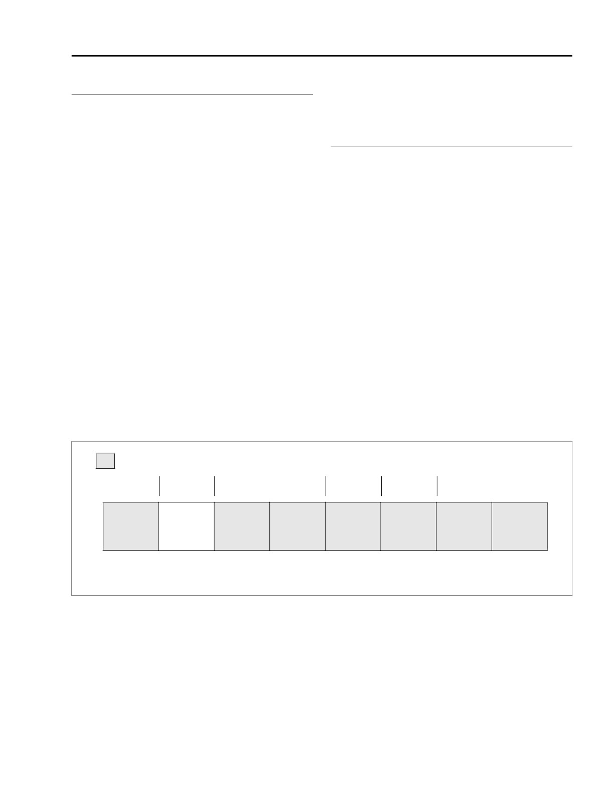
10=Headset
11=Speaker
0=PTT
0 or 1
1=Break
1=ON
1=ON
01=Center
AVC
HAND-
CB
INTERCOM
CB
SPEAKER
SPEAKER
VEHICLE
VOX
HELD MIC.
SQUELCH
OFF/ON
OFF/ON
SWITCH
SWITCH
SPEED
BREAK
PTT
BREAK
SWITCH
SWITCH
“B”
“A”
SIGNAL
7
6
5
4
3
2
1
0
(BE/Y)
(W/GN)
Internal
Internal
Internal
Internal
(BN/O)
(V/O)
Figure 6-27. Diagnostic Mode Group 2
2005 Touring: Sound System
6-41
HOME
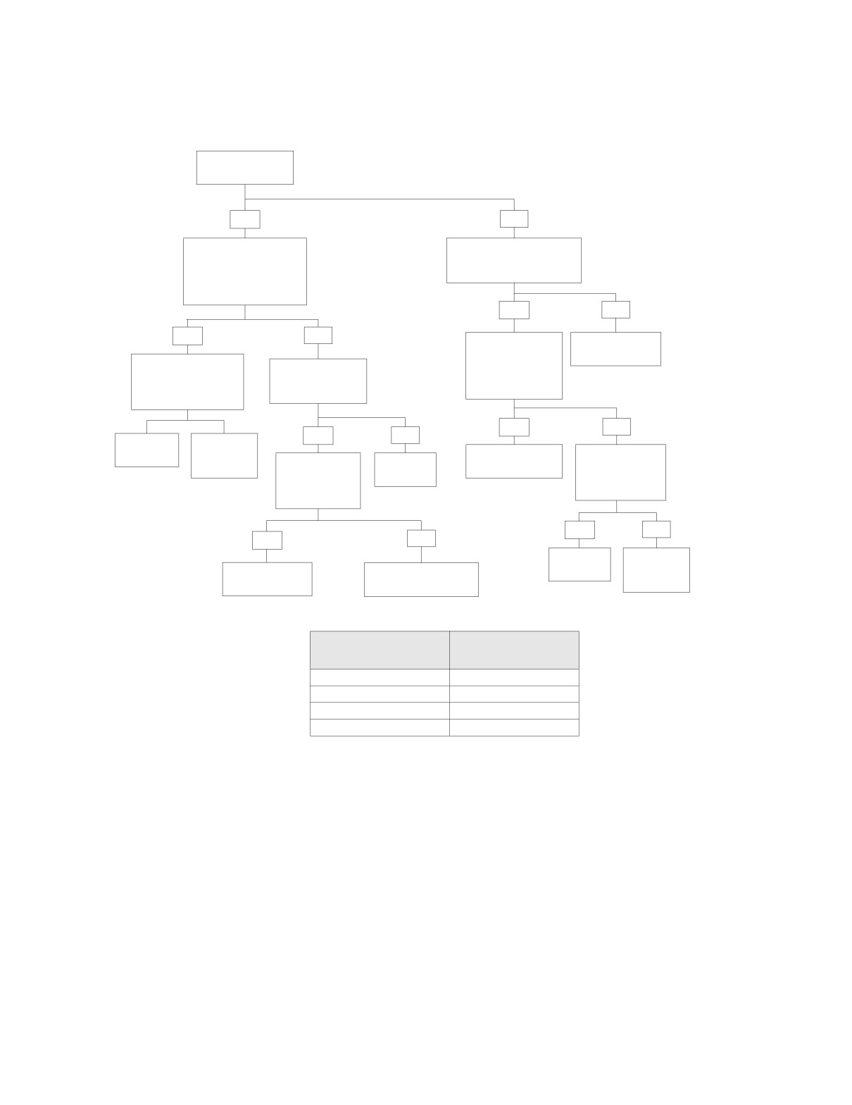
Test 6.15 (Part 1 of 2)
CB TRANSMITTER INOPERATIVE: SOFTWARE DIAGNOSIS
Did Radio Enter
CB Setup Mode?
YES
NO
Tune Known Good
Enter Diagnostic Mode 2.
Receiver to Same
Does CB OFF/ON Switch
Channel Number as
Display “1” in LCD?
Transmitter. Test Trans-
mitter. Transmitter OK?
YES
NO
YES
NO
Does Handheld
Go to Test 6.15
Microphone Dis-
(Part 2 of 2).
Perform Antenna
play “0” in LCD
Does Unit Under
Check and SWR
With PTT Switch
Test Receiver
Adjustment Proce-
Not Pushed In?
Work OK?
dures.
YES
NO
YES
NO
Replace
Replace
CB Mast.
CB Load
Go to Test 6.17
Does Radio
Coil.
Does Display
Replace
(Part 1 of 2).
Work Normally
6613
Change When
Radio.
Except for CB
6618
PTT is
Transmitter?
6601
Depressed?
YES
NO
YES
NO
Replace
Diagnose
Radio.
Other
Go to Test 6.15
Go to the Appropriate
(Part 2 of 2).
PTT Inoperative Chart.
Symptom.
6601
PTT INOPERATIVE
CONTINUE WITH
CHART
Rear Headset Volume PTT
6.12 RADIO SYMPTOM 9
Sidecar PTT
6.12 RADIO SYMPTOM 9
PTT/Squelch
6.16 RADIO SYMPTOM 13
Handheld Microphone/PTT
6.17 RADIO SYMPTOM 14
After correction of problem, refer to SETUP and
FUNCTIONALITY to verify proper operation.
6-42
2005 Touring: Sound System
HOME
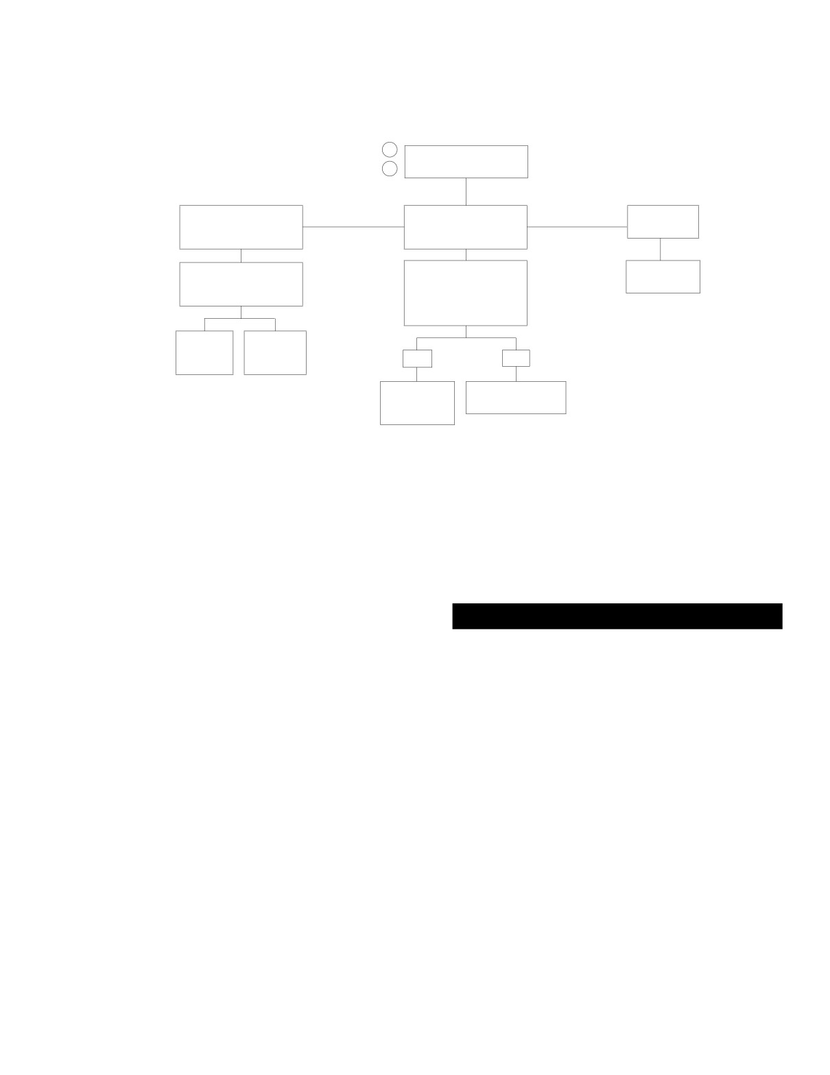
Test 6.15 (Part 2 of 2)
CB TRANSMITTER INOPERATIVE: HARDWARE DIAGNOSIS
1
Does Lamp Glow When
2
Transmitting?
Lamp Glows and
Lamp Glows But No
Lamp Does
Changes in Brilliance
Change in Brilliance
Not Glow.
While Speaking.
While Speaking.
Perform Antenna Check
Substitute Known Good
Replace
and SWR Adjustment
Microphone. Repeat
Radio.
Procedures.
Test. Does Lamp Glow
6601
and Change in Bril-
liance While Speaking.
Replace
Replace
CB
CB Load
YES
NO
Mast.
Coil.
6613
6618
Replace
Go to Test 6.11
Microphone
(Part 2 of 2).
or Headset.
After correction of problem, refer to SETUP and
FUNCTIONALITY to verify proper operation.
CB Antenna Test
SWR Adjustment
A faulty CB antenna can cause poor reception and transmit-
ting range. Check the antenna system as follows:
CAUTION
1. Remove outer fairing. Remove antenna cable from back
Do not press PTT switches with antenna and SWR meter
of radio. Using clip-on test leads, connect one lead of
disconnected. Transceiver damage could result.
ohmmeter to center pin in antenna lead and other lead to
antenna mast. Meter must read 1 ohm or less. Wiggle or
Standing wave ratio (SWR) is a technical term for the proce-
flex mast while observing meter. If resistance is more
dure that checks how well the CB transmitter and antenna are
than 1 ohm or varies when mast is wiggled, replace
matched. The SWR should be 2:1 or below on channel 20. A
mast. Inspect connections at base of loading coil and at
SWR of 1:1 is optimum.
mounting bracket.
To check SWR, a SWR meter or bridge is required. Your Har-
NOTE
ley-Davidson dealer will either have a SWR meter or direct
It is normal to observe a reading of less than one ohm
you to a CB repair shop for a SWR check. Since the operating
between the center conductor and ground due to the configu-
procedures for SWR meters vary, be sure you carefully follow
ration of the loading coil.
the operating instructions for the SWR meter being used.
2. Check SWR adjustment.
1. Locate motorcycle outdoors or in a building with a ceiling
of 11 ft. (3.4 m) minimum above floor. Also, there must
3. To replace the CB antenna, see the Touring Models Ser-
be 8 ft. (2.4 m) of radial clearance around motorcycle.
vice Manual.
Adjusting the SWR in an area with a lower ceiling and/or
less radial clearance may result in an inaccurate adjust-
ment.
2005 Touring: Sound System
6-43
HOME
2.
Remove the outer fairing. Remove the antenna cable
9. If SWR is more than 3:1, remove antenna cable from
and connect the SWR meter to the radio. Connect the
transceiver under Tour-Pak. Using clip-on test leads,
antenna cable to the SWR meter. The SWR meter is
connect one lead of ohmmeter to center pin in antenna
connected in series with the antenna cable so the
lead and other lead to antenna mast. Meter must read 1
antenna will be connected to the SWR meter.
ohm or less. Wiggle or flex mast while observing meter. If
resistance is more than 1 ohm or varies when mast is
3.
Check that the antenna loading coil bracket in Tour-Pak
wiggled, replace mast. Inspect connections at base of
is tight and that antenna cable is tightly connected to
loading coil and at mounting bracket. If the SWR is less
loading coil.
than 3:1, loosen antenna set screw and change mast
length.
4.
Check that antenna mast is threaded securely on to base
and set screw is tight.
NOTE
5.
Before measuring the SWR, the SWR meter must be cal-
It is normal to observe a reading of less than one ohm
ibrated. Follow the instructions for the meter being used.
between the center conductor and ground due to the configu-
The following procedure is the general calibration most
ration of the loading coil.
meter instructions specify.
10. Repeat Step 8. If SWR became higher, adjust antenna
mast in opposite direction. Continue adjusting antenna
CAUTION
until the minimum SWR is achieved. If you cannot obtain
Do not touch the antenna or meter during calibration or
an SWR of 2:1 or less by adjusting the antenna length,
SWR measurement. Move CAL knob and then move your
make the mast shorter to improve the SWR. Remove
hand away from meter while calibrating.
mast and use grinder to shorten mast (grind in small
increments).
6. With ignition and CB switches ON, the SWR meter set on
11. After SWR is adjusted on channel 20, check SWR on
“FWD”, Channel 20 selected, press either PTT switches.
channels 1 and 40. Adjust the mast length to obtain a
Hold the PTT switch and rotate the calibration (CAL)
balance between channels 1 and 40.
control until the meter needle aligns with the “CAL” mark.
7. Release the PTT switch and move the FWD/REF switch
NOTE
to “REF” (reflected).
Check the SWR if a luggage rack is installed on the Tour-Pak
cover. Be sure that the Tour-Pak cover is closed when the
check is performed. Accessories mounted on the Tour Pak
CAUTION
may affect the SWR reading and broadcast range, so the lug-
Do not touch the antenna or meter during calibration or
gage rack should be mounted as far forward as possible. The
SWR measurement. Move CAL knob and then move your
Ultra Tour-Pak chrome accent rail also can adversely affect
hand away from meter while calibrating. Do not press
SWR.
PTT switches with antenna and SWR meter discon-
nected. Transceiver damage could result.
8.
Press and hold either PTT switch. The meter reading is
the SWR.
6-44
2005 Touring: Sound System
HOME
RADIO SYMPTOM 13
6.16
GENERAL
Not Applicable to Classic/Road Glide Models
C4
C3
C2
C1
CO
Problem
(BN/W)
(O/BK)
(BN/BK)
(GY/GN)
(GN/BE)
PTT/Squelch control inoperative.
RO
MODE UP
REAR
AUDIO
AUDIO
AUDIO
(PK/W)
FF
VOLUME
IN
-
+
UP
REAR
R1
MODE DN
RADIO
VOLUME
EJECT
LO/DX
Setup
(GY/W)
RW
POWER
DOWN
R2
MODE
SQUELCH
SQUELCH
SEEK
● Press the POWER button to turn the radio ON.
PTT
(V/BK)
IN
DOWN
UP
SCAN
● Press and hold the INT button to turn the Intercom OFF.
R3
NOT
PRESET
PRESET
PRESET
PRESET
(INT)
USED
4
3
2
1
● Press and hold the CB button to turn the Citizen Band
radio ON.
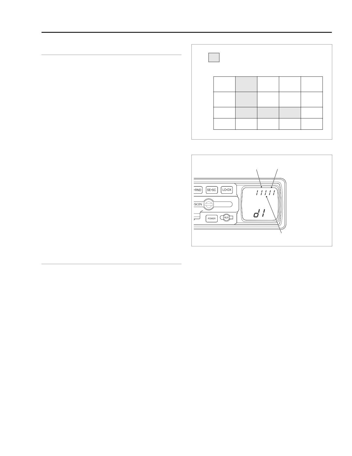
Figure 6-28. Diagnostic Mode Group 1 Switch Matrix
● Set fairing mounted Headset/Speaker Switch to
SPEAKER.
f2123x8x
C3
C1
Functionality
Depressing any PTT switch will change
the radio display to
reflect CB mode and cause the transmitter to transmit. Press-
ing the Squelch Control in either direction will cause the hori-
zontal bar graph display to change. Are these your
observations?
● Yes - System is OK.
● No - See Test 6.16 (Part 1 of 2).
C2
Figure 6-29. PTT/Squelch Control Switch Input Bits
DIAGNOSTICS
3. Revalidate failure. Reconnect all connectors. If problem
Diagnostic Notes
still exists, replace radio. If problem is gone, look for
intermittents.
The reference numbers below correlate with the circled num-
bers in the Test 6.16 flow charts.
4. Use HARNESS CONNECTOR TEST KIT (Part No. HD-
41404A), black pin probes and patch cord.
1. This also may be an open. First go to SHORT TO VOLT-
AGE in Test 6.16 (Part 2 of 2).
2. Install BREAKOUT BOX (Part No. HD-44608). See Sec-
tion 6.3 BREAKOUT BOX, INSTALLATION.
2005 Touring: Sound System
6-45
HOME
Test 6.16 (Part 1 of 2)
PTT/SQUELCH CONTROL INOPERATIVE: SOFTWARE DIAGNOSIS
Enter Diagnostic Mode
by Pressing Any Two Pre-
set Buttons While Turning
Ignition Switch to On.
Look at Input Bits C1,
C2 and C3 in LCD Dis-
play. See Figure 6-29.
Do Any of the Input Bits
Display “0?”
YES
NO
Move to Test 6.16 (Part 2 of 2) to Find
Exercise All Three Posi-
Short to Ground on Any Wire Where
tions of PTT/SQUELCH
Corresponding Input Bit Displays “0.”
CONTROL SWITCH. Do
All of the Corresponding
Switch
Input
Wire
Input Bits Toggle
Position
Bit
Color
Between “1” and “0?”
Squelch +
C1
GY/GN
Squelch -
C2
BN/BK
PTT
C3
O/BK
YES
NO
Switch and
Activate Switch Where
Wiring are OK.
Corresponding Input Bit
Replace Radio.
Does Not Toggle
Between “1” and “0?” Is it
6601
a “0” or a “1” While Switch
is Activated?
0
1
Move to Test 6.16
1
Move to Test 6.16 (Part 2 of 2) to
(Part 2 of 2) to
Find Short to Voltage on Wire
Find Short to
Where Corresponding Input Bit Dis-
Ground on R2
plays “1” (With No Switches
(V/BK) Wire.
Depressed).
Switch
Input
Wire
Position
Bit
Color
Squelch +
C1
GY/GN
Squelch -
C2
BN/BK
PTT
C3
O/BK
All Positions
All
V/BK
After correction of problem, refer to SETUP and
FUNCTIONALITY to verify proper operation.
Table 6-9. FLHTCU Wire Harness Connectors
NO.
DESCRIPTION
TYPE
LOCATION
Interconnect Harness to
[24]
12-Place Deutsch (Gray)
Inner Fairing- Left Fairing Support Brace
Left Handlebar Switch Controls
[27]
Radio
23-Place Amp (Black)
Inner Fairing- Back of Radio (Right Side)
6-46
2005 Touring: Sound System
HOME
Test 6.16 (Part 2 of 2)
PTT/SQUELCH CONTROL INOPERATIVE: HARDWARE DIAGNOSIS
What Did
Test 6.16 (Part 1 of 2) Indicate?
SHORT to VOLTAGE
SHORT to GROUND
Remove Outer Fairing. Connect Breakout Box
2
2
Remove Outer Fairing. Connect Breakout
leaving Connector [27B] Disconnected from
Box leaving Connector [27B] Discon-
Radio. With Key ON, Check for Power at
nected from Radio. With Key OFF, Check
Connector [27B].
for Continuity to Ground at Connector
[27B].
From (-)
To Terminal (+)
5 (V/BK)
From
To Terminal
7 (O/BK)
5 (V/BK)
Ground
8 (BN/BK)
7 (O/BK)
Ground
22 (GY/GN)
8 (BN/BK)
22 (GY/GN)
Is Voltage Present?
Any Continuity Present?
YES
NO
YES
NO
With Key ON, Check for Power
4
OPEN
With Key OFF, Check for
3
Replace
at Connector [24B].
Continuity to Ground at
Radio.
Disconnect Connector [27B]. With
Connector [24B].
To
From
Switch Depressed, Check for
6601
Terminal
(-)
Continuity at Connector [27B].
To
(+)
From
Terminal
7 (V/BK)
Switch
From
To
(-)
(+)
8 (BN/BK)
Position
Terminal
Terminal
Ground
7 (V/BK)
11 (GY/GN)
Squelch +
5 (V/BK)
22 (GY/GN)
8 (BN/BK)
12 (O/BK)
Squelch -
5 (V/BK)
8 (BN/BK)
Ground
11 (GY/GN)
PTT
5 (V/BK)
7 (O/BK)
Is Voltage Present?
12 (O/BK)
Each Wire Pair Should be Less than 0.5
Any Continuity Present?
4
Ohms While Switch is Depressed and
Infinity While Switch is Open. Is It?
YES
NO
YES
NO
YES
NO
Locate
Locate and
and
Repair Short
Locate and
Locate and
Repair
in Interconnect
3
Replace
With Switch Depressed, Check for
Repair Short in
Repair Short
Short in
Harness.
Radio.
Continuity at Connector [24B].
Handlebar
in Interconnect
Handle-
bar Har-
6531
6601
Harness.
Harness.
Switch
From
To
ness.
Position
Terminal
Terminal
6551
6531
6551
Squelch +
7 (V/BK)
11 (GY/GN)
Squelch -
7 (V/BK)
8 (BN/BK)
PTT
7 (V/BK)
12 (O/BK)
Each Wire Pair Should be Less than 0.5
Ohms While Switch is Depressed and
Infinity While Switch is Open. Is It?
4
YES
NO
Locate and Repair
Replace PTT/
Open or Replace
Squelch Control
Interconnect
Switch or Repair
Harness.
Switch Wiring.
6532
5184
After correction of problem, refer to SETUP and
FUNCTIONALITY to verify proper operation.
2005 Touring: Sound System
6-47
HOME
RADIO SYMPTOM 14
6.17
GENERAL
DIAGNOSTICS
Problem
Diagnostic Notes
Handheld microphone PTT inoperative.
The reference numbers below correlate with the circled num-
bers in the Test 6.17 flow charts.
Setup
1.
Install BREAKOUT BOX (Part No. HD-44608). See Sec-
tion 6.3 BREAKOUT BOX, INSTALLATION.
● Press the POWER button to turn the radio ON.
2.
Use HARNESS CONNECTOR TEST KIT (Part No. HD-
● Press and hold the INT button to turn the Intercom OFF.
41404A), black pin probes and patch cords.
● Press and hold the CB button to turn the Citizen Band
radio ON.
3.
Use HARNESS CONNECTOR TEST KIT (Part No. HD-
41404A), black socket probes and patch cord.
● Set fairing mounted Headset/Speaker Switch to
SPEAKER.
Functionality
Depressing handheld PTT switch will change the radio dis-
play to reflect CB mode and cause the transmitter to transmit.
In CB Setup mode, the squelch display will disappear when
PTT is depressed. Are these your observations?
● Yes - System is OK.
● No - See Test 6.17 (Part 1 of 2).
6-48
2005 Touring: Sound System
HOME
Test 6.17 (Part 1 of 2)
HANDHELD MICROPHONE PTT INOPERATIVE: SOFTWARE DIAGNOSIS
Which PTT Switch
Does Not Work?
Rider/Passenger
Handheld Microphone
Enter Diagnostic Mode
Enter Diagnostic Mode
1. Is Input Bit C3 Dis-
2. With Microphone
played in LCD as “1?”
Disconnected, Is PTT
Input Bit Displayed in
LCD as “0?”
YES
NO
YES
NO
Press Rider/Passen-
Go to Test 6.17
ger PTT Switch. Does
(Part 2 of 2).
Input Bit C3 Displayed
Go to Test 6.17
Plug In Handheld
in LCD Toggle
(Part 2 of 2).
Microphone. Is PTT
Between “1” and “0”
Input Bit Displayed in
While PTT Switch is
LCD as “0” While PTT
Depressed?
IS NOT Depressed on
Microphone.
YES
NO
YES
NO
Rider/Pas-
Which PTT
Replace Microphone
Depress Microphone
senger PTT
Switch is
Switch OK.
Inoperative?
With Unit Known To Be
PTT Switch. Does
Good. Does New
PTT Input Bit Dis-
Microphone Work?
played in LCD
Change From “1” to
“0” When Button is
Depressed?
YES
NO
Handheld Micro-
Go to Test 6.17
YES
NO
phone PTT Circuit
(Part 2 of 2).
is OK.
Handheld
Replace Microphone
Microphone
With Unit Known To Be
PTT Circuit is
Good. Does New
OK.
Microphone Work?
YES
NO
Rider
Rear Passenger
Sidecar
Handheld
Go to
Microphone
Test 6.17
Go to Test 6.16
Go to Test 6.12
Go to Test 6.12
PTT Circuit
(Part 2 of 2).
(Part 2 of 2).
(Part 2 of 3).
(Part 3 of 3).
is OK.
After correction of problem, refer to SETUP and
FUNCTIONALITY to verify proper operation.
Table 6-10. FLHTCU Wire Harness Connectors
NO.
DESCRIPTION
TYPE
LOCATION
[27]
Radio
23-Place Amp (Black)
Inner Fairing- Back of Radio (Right Side)
[28]
Radio
23-Place Amp (Gray)
Inner Fairing- Back of Radio (Left Side)
[53]
Console Pod
12-Place Mini-Deutsch (Black)
Rear of Battery Box (Under Seat)
2005 Touring: Sound System
6-49
HOME
Test 6.17 (Part 2 of 2)
HANDHELD MICROPHONE PTT INOPERATIVE: HARDWARE DIAGNOSIS
Use Microphone
Known to be Good.
Problem Still Exists?
YES
NO
Place in Diagnostic Mode.
Replace
What did Test 6.17 (Part 1
Microphone.
of 2) Indicate?
OPEN
SHORT
Connect Breakout Box to Harness Only.
1
1
Check for Continuity as Follows:
Check for Continuity as Follows:
2
FROM
TO
2
FROM
TO
Connector
Terminal
Connector
Terminal
Connector
Terminal
Ground
Front
[27B]
2 (BE/Y)
[27B]
2 (BE/Y)
7
Headset DIN
Should Read Infinity. Does It?
Front
[28B]
2 (Y/BK)
6
Headset DIN
Each Wire Should be Less than 0.5 Ohms. Is It?
YES
NO
YES
NO
Replace
Disconnect Connector [53]. Check
Radio.
for Continuity as Follows:
Replace
2
Check for Continuity as Follows:
6601
FROM
TO
Radio.
Connector
Terminal
FROM
TO
Ground
6601
[27B]
2 (BE/Y)
Connector
Terminal
Connector
Terminal
[27B]
2 (BE/Y)
[53B]
6
Should Read Infinity. Does It?
[28B]
2 (Y/BK)
[53B]
7
Each Wire Should be Less than 0.5 Ohms. Is It?
YES
NO
Replace Pod
Repair
YES
Y/BK
BE/Y
Headset
Audio
NO
NO
Harness.
Harness.
6616
6560
Replace Pod
Repair
Check for Continuity as Follows:
Headset
Audio
Harness.
Harness.
FROM
TO
Connector
Terminal
Connector
Terminal
6616
6561
[27B]
2 (BE/Y)
[6A]
4 (BE/Y)
Continuity Present?
3
YES
NO
Replace Pod
Repair
Headset
Audio
Harness.
Harness.
6616
6561
After correction of problem, refer to SETUP and
FUNCTIONALITY to verify proper operation.
6-50
2005 Touring: Sound System
HOME
RADIO SYMPTOM 15
6.18
GENERAL
Functionality
Problem
CB audio should be heard in headset and stereo audio
should be heard in fairing speakers. Is it?
No CB audio in headset in center position.
● Yes - System is OK.
● No - See Test 6.18.
Setup
● Press the POWER button to turn the radio ON.
DIAGNOSTICS
● Press and hold the INT button to turn the Intercom OFF.
● Press and hold the CB button to turn the Citizen Band
radio ON.
Diagnostic Notes
● Set fairing mounted Headset/Speaker Switch to CEN-
The reference number below correlates with the circled num-
TER position.
ber in the Test 6.18 flow chart.
● Set Volume Control to Middle position on horizontal bar
1. If the lamp is missing or the filament is broken, Speaker
graph display.
B, Speaker A input bits are displayed in LCD as “11” with
the Headset/Speaker Switch in the center position. In
● Set Squelch Control to receive incoming CB signals.
other words, the system functions as though the switch is
in the SPEAKER position.
Test 6.18
NO CB AUDIO IN HEADSET IN CENTER POSITION: SOFTWARE DIAGNOSIS
Enter Diagnostic Mode “d2.”
Set Fairing Mounted Headset/
Speaker Switch to SPEAKER.
Is Red Lamp Illuminated?
YES
1
NO
Are Speaker B, Speaker
Go to Test 6.6 (Part 2 of 3)
A Input Bits Displayed in
(speakers) or Test 6.11
YES
LCD as “11?”
(Part 2 of 2) (headsets).
Set Fairing Mounted
Headset/Speaker Switch
to HEADSET.
YES
NO
Are Speaker B, Speaker
A Input Bits Displayed in
LCD as “10?”
Set Fairing Mounted
Go to Test 6.6 (Part 2 of 3)
Headset/Speaker Switch
(speakers) or Test 6.11
to CENTER Position.
(Part 2 of 2) (headsets).
Are Speaker B, Speaker A
YES
NO
Input Bits Displayed in
LCD as “01?”
Headset/
Go to Test 6.6 (Part 2 of 3)
Speaker Switch
(speakers) or Test 6.11
and Wiring OK.
(Part 2 of 2) (headsets).
NO
Go to Test 6.6 (Part 2 of 3)
(speakers) or Test 6.11
(Part 2 of 2) (headsets).
2005 Touring: Sound System
6-51
HOME
NOTES
6-52
2005 Touring: Sound System
Table Of Contents
SUBJECT
PAGE NO.
7.1 Cruise Control
7-1
7.2 Cruise Inoperative Diagnostics
7-3
7.3 Cruise Dropout Diagnostics
7-6
7.4 Cruise Chart A: Initial Diagnostics
7-9
7.5 Cruise Chart B: Resume Switch
7-11
7.6 Cruise Chart C: Cruise Engaged Lamp
7-12
7.7 Cruise Chart D: Cruise Power
7-13
7.8 Cruise Chart E: Cruise Enable
7-15
7.9 Cruise Chart F-1: Brake Lights ON
7-16
7.10 Cruise Chart F-2: Brake Lights OFF
7-17
7.11 Cruise Chart G: Throttle Switch
7-19
7.12 Cruise Chart H: Speedometer Input
7-20
7.13 Cruise Chart I: Tachometer Input
7-21
CRUISE CONTROL
7