Harley Davidson 2005 touring models. Service repair manual - page 47
HOME
f2332e8x
[156B] [156A]
Main to Interconnect
6
6
Harness
5
5
4
4
3
3
GY
BK
2
2
BK
LtGN/V
1
1
LtGN/V
O
1
2
3
4 5 6 7 8 9 10 11 12
[30B]
BN/GY
1
2
3
4 5 6 7 8 9 10 11 12
[30A]
TSM/TSSM
BN/GY
[39B]
GY
BK
1
2
3
4 5 6 7 8 9 10 11 12
[39A]
1
2
3
4 5 6 7 8 9 10 11 12
1
2
3
4 5 6 7 8 9 10 11 12
[8B]
Speedometer
1
2
3
4 5 6 7 8 9 10 11 12
1
2
3
4 5 6 7 8 9 10 11 12
[8A]
[108B]
1
2
3
4 5 6 7 8 9 10 11 12
Ignition
To
[108A]
Harness
Ignition
Tachometer
Keyswitch
Relay
15A
Instruments
[1B] [1A]
Fuse
1
2
Main to Interconnect
3
[2A]
1
2
3
4 5 6 7 8 9 10 11 12
Harness
4
Data Link
[2B]
1
2
3
4 5 6 7 8 9 10 11 12
[91A]
Main to Interconnect
15A
Harness
Ignition
Fuse
12
15A
[10B]
Battery
12
[10A]
Ignition Control Module
Fuse
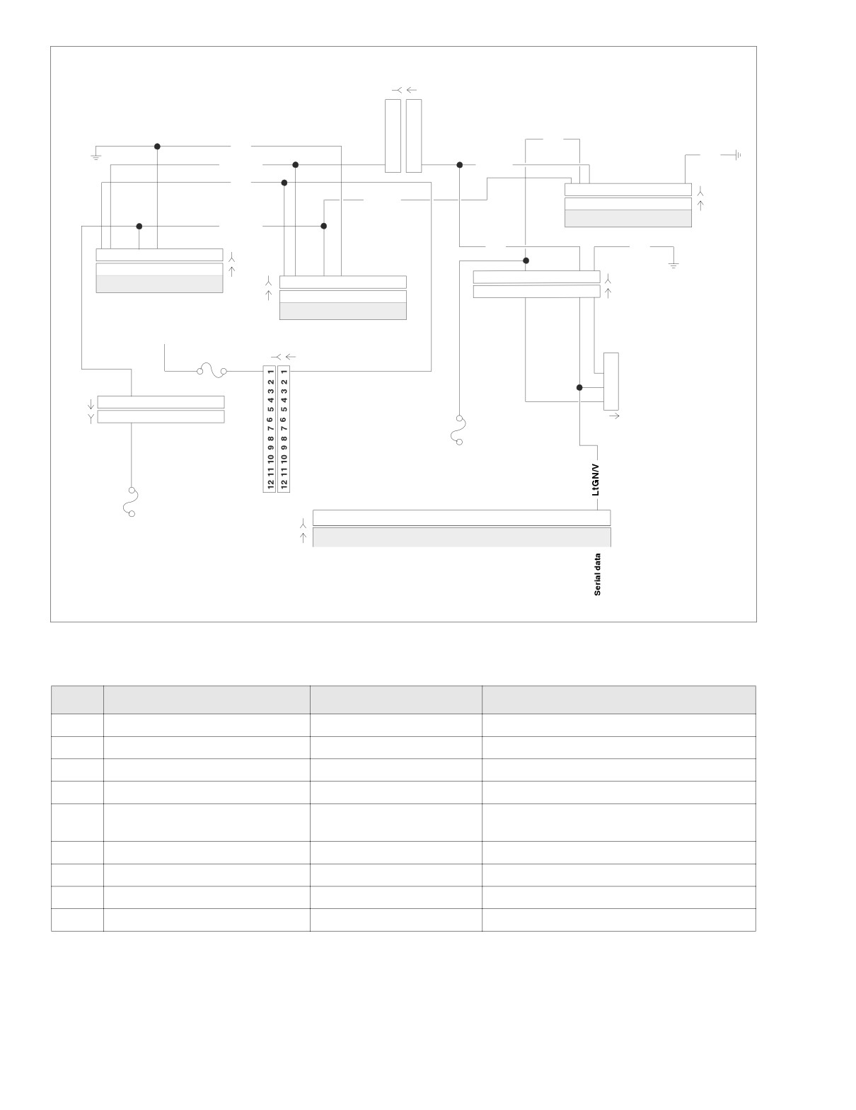
Figure 4-29. Serial Data Circuit (FLHT/C)
Table 4-20. Wire Harness Connectors in Figure 4-29.
NO.
DESCRIPTION
TYPE
LOCATION
[1]
Main to Interconnect Harness
12-Place Deutsch (Black)
Inner Fairing - Right Radio Support Bracket
[2]
Main to Interconnect Harness
12-Place Deutsch (Gray)
Inner Fairing - Right Fairing Support Brace
[8]
Ignition Harness
12-Place Deutsch
Under Right Side Cover
[10]
Ignition Control Module
12-Place Deutsch
Under Right Side Cover
Cavity in Crossmember at Rear of
[30]
Turn Signal/Security Module
12-Place Deutsch
Battery Box (Under Seat)
[39]
Speedometer
12-Place Packard
Inner Fairing (Back of Speedometer)
[91]
Data Link
4-Place Deutsch
Under Right Side Cover
[108]
Tachometer
12-Place Packard
Inner Fairing (Back of Tachometer)
[156]
Main to Interconnect Harness
6-Place Deutsch
Inner Fairing - Right Fairing Support Brace
4-42
2005 Touring: Engine Management (Carbureted)
HOME
f2332d8x
BK
GY
LtGN/V
LtGN/V
BK
BN/GY
O
1
2
3
4
5 6 7 8 9 10 11 12
[30B]
1
2
3
4
5 6 7 8 9 10 11 12
[30A]
BN/GY
TSM/TSSM
BK
1
2
3
4 5 6 7 8 9 10 11 12
[39B]
1
2
3
4 5 6 7 8 9 10 11 12
[39A]
GY
Speedometer
1
2
3
4
5
6
7
8
9
10 11 12
[8B] Ignition
15A
1
2
3
4
5
6
7
8
9
10 11 12
[8A] Harness
Instruments
Fuse
15A
Battery
Fuse
1
To
2
Ignition
Keyswitch
3
Relay
4
Data Link
[91A]
15A
Ignition
Fuse
12
[10B]
[10A]
Ignition Control Module
12
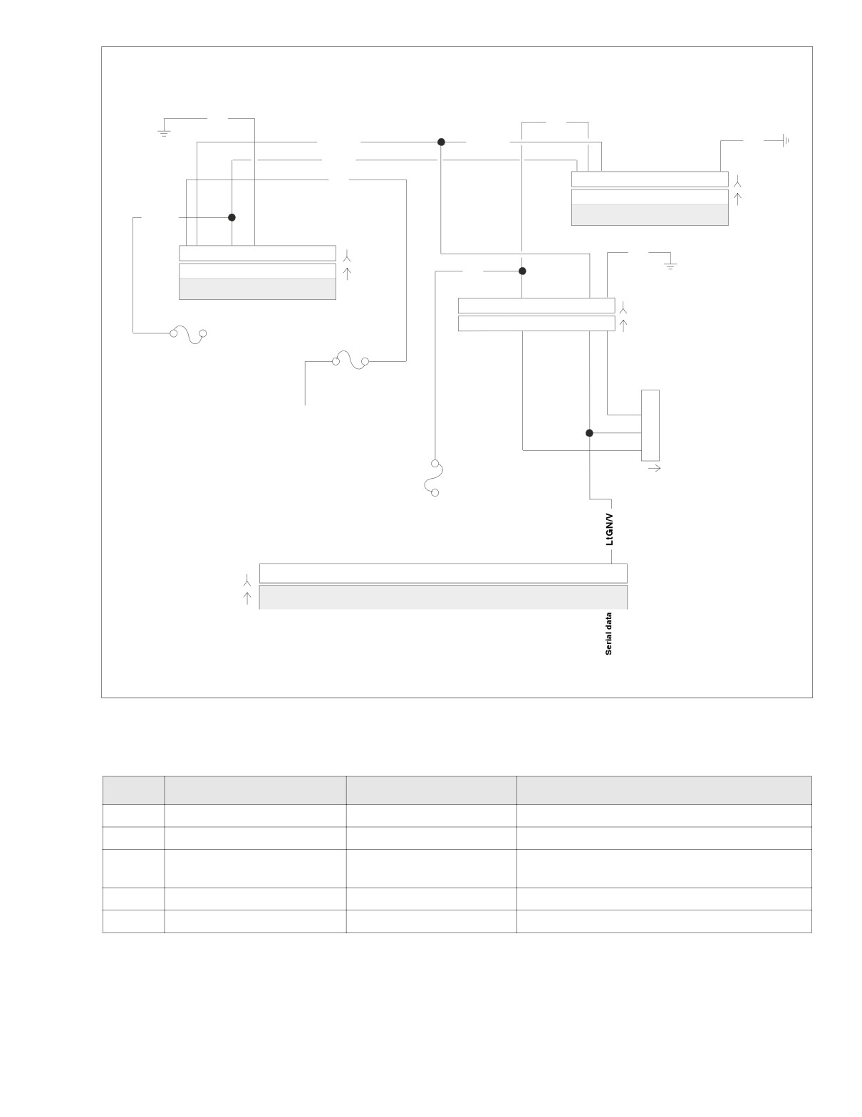
Figure 4-30. Serial Data Circuit (FLHR/S)
Table 4-21. Wire Harness Connectors in Figure 4-30.
NO.
DESCRIPTION
TYPE
LOCATION
[8]
Ignition Harness
12-Place Deutsch
Under Right Side Cover
[10]
Ignition Control Module
12-Place Deutsch
Under Right Side Cover
Cavity in Crossmember at Rear of
[30]
Turn Signal/Security Module
12-Place Deutsch
Battery Box (Under Seat)
[39]
Speedometer
12-Place Packard
Under Console (Back of Speedometer)
[91]
Data Link
4-Place Deutsch
Under Right Side Cover
2005 Touring: Engine Management (Carbureted)
4-43
HOME
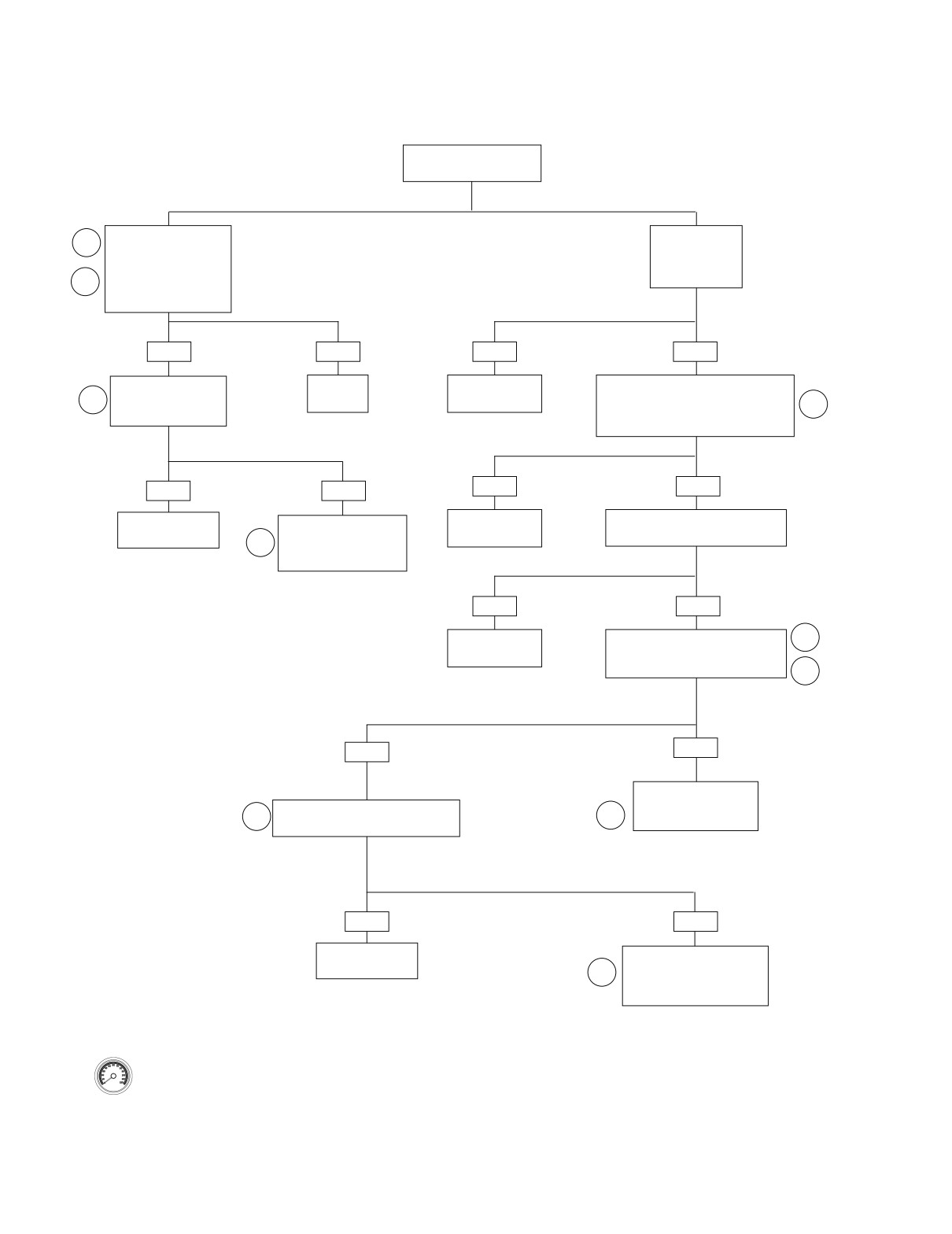
Test 4.15
PASSWORD PROBLEM: DTC P1009, P1010
Which diagnostic trouble
code was set?
DTC P1009.
DTC P1010.
1
Bad password.
No password.
Reprogram password.
Are there any
See 3.24 PASSWORD
U-codes set?
4
LEARN.
DTC P1009 still exist?
YES
NO
YES
NO
Replace TSSM and
System
Troubleshoot
Remove ICM connector [10]. Check
relearn password.
OK.
lowest U-code.
for continuity to ground at data
4
System OK?
connector [91A] Terminal 3.
2
6701
Continuity present?
YES
NO
YES
NO
System
Repair short
Check for battery voltage on Pin 3.
Reinstall original TSSM.
OK.
to ground.
Battery voltage present?
Replace ICM.
5
Reprogram and relearn
6704
6702
password.
6703
YES
NO
Repair short
Test data connector [91A]
2
to voltage.
Terminal 3 against Breakout Box Pin
12 for continuity. Continuity present?
6705
3
YES
NO
Inspect terminals
for damage or repair
Replace TSM/TSSM and relearn
4
2
opens as necessary.
password. System OK?
6706
YES
NO
System
Reinstall original TSSM.
OK.
Replace ICM.
4
Reprogram and relearn
6707
password.
6708
Clear codes using speedometer self diagnostics.
See 4.5 SPEEDOMETER SELF DIAGNOSTICS.
Confirm proper operation with no check engine
lamp.
4-44
2005 Touring: Engine Management (Carbureted)
HOME
DTC P1351, P1352, P1354, P1355
4.16
GENERAL
10561
Ignition Coil
Ignition coil codes will set if the ignition coil primary voltage is
out of range. This could occur if there is an open coil or loss of
power to the coil. If front and rear codes are set simulta-
neously, it is likely a coil power failure or a coil failure.
The coil receives power from the engine run/stop switch. The
ignition control module is responsible for turning on the coils
by providing the ground to activate the coils, which in turn
powers the coils.
Table 4-22. Code Description
DTC
DESCRIPTION
P1351
Front ignition coil open/low
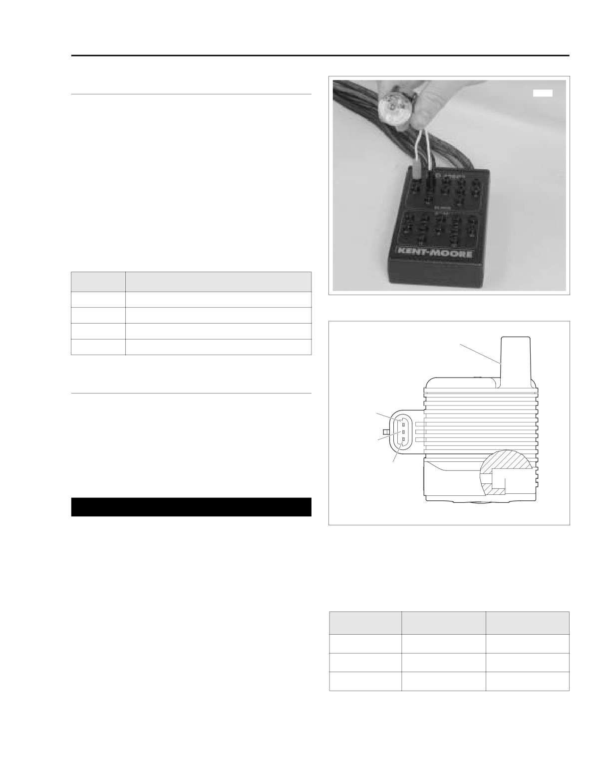
Figure 4-31. Ignition Coil Circuit Test
P1352
Front ignition coil high/shorted
P1354
Rear ignition coil open/low
s0592x8x
Coil tower
P1355
Rear ignition coil high/shorted
DIAGNOSTICS
C
Diagnostic Notes
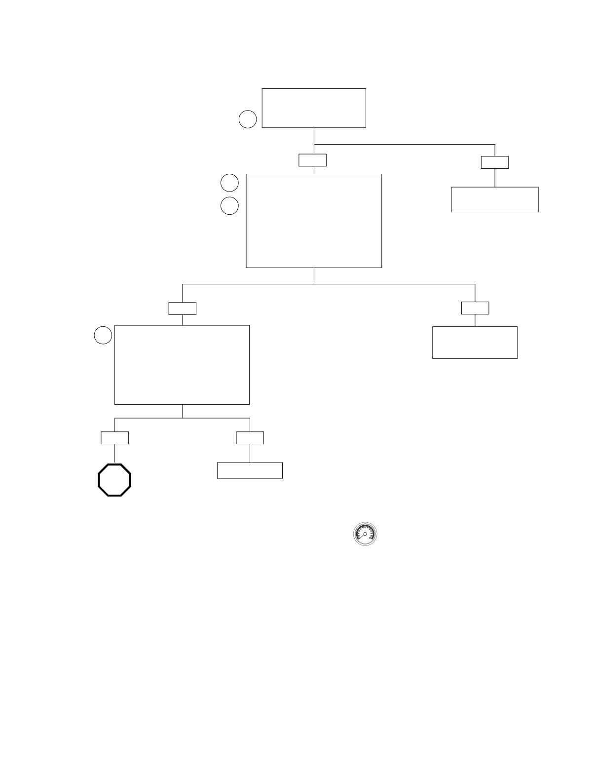
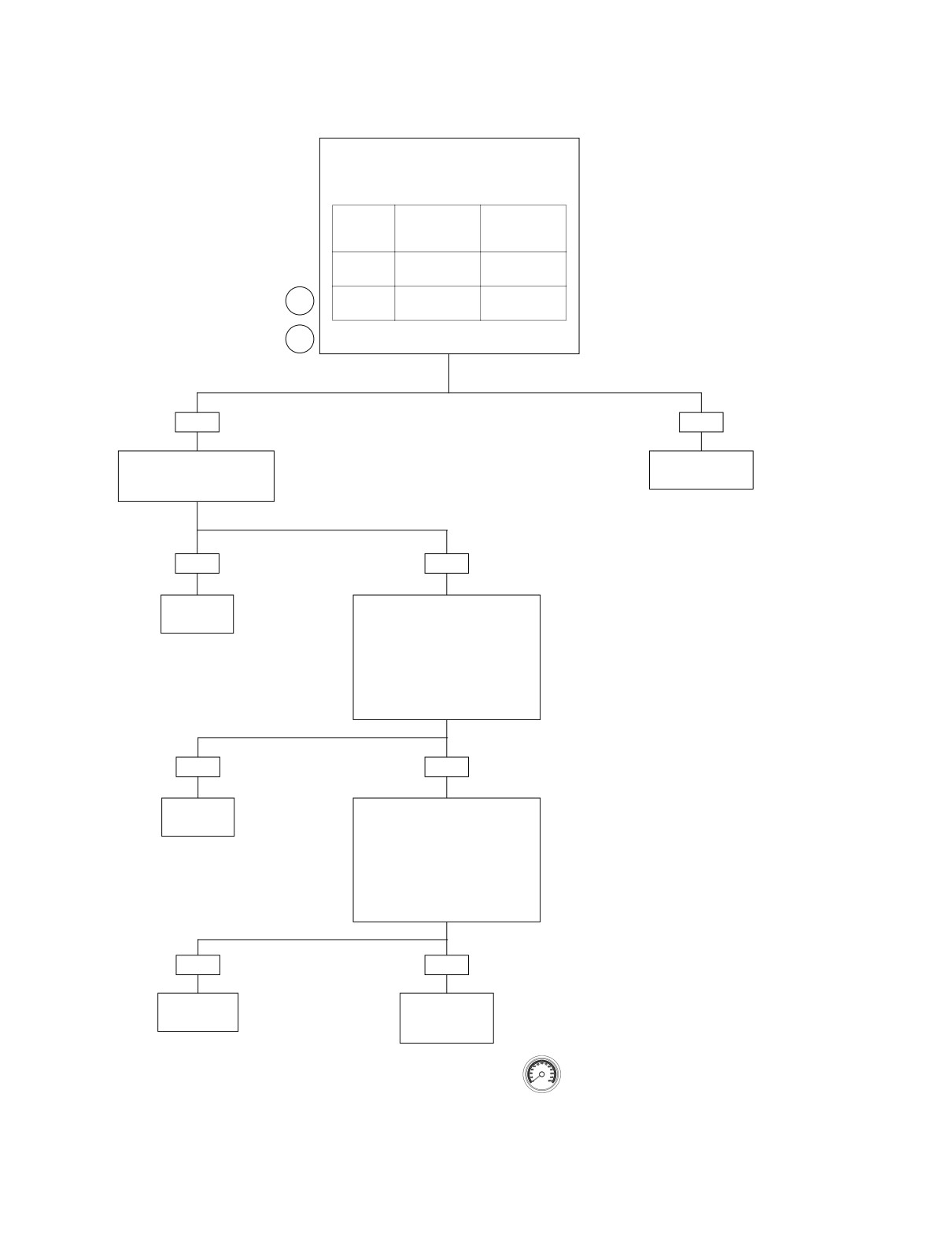
The reference numbers below correlate with the circled num-
B
bers on the Test 4.16 flow charts.
1. Use HARNESS CONNECTOR TEST KIT (Part No. HD-
A
41404A), gray pin probes and patch cord.
CAUTION
Gently connect test lamp to connector [83B]. Forcefully
Figure 4-32. Ignition Coil Connector Terminals
inserting test lamp will result in ignition connector termi-
nal damage.
2. See Figure 4-31. Plug IGNITION COIL CIRCUIT TEST
4.
Use HARNESS CONNECTOR TEST KIT (Part No. HD-
ADAPTER (Part No. HD-44687) and FUEL INJECTOR
41404A), gray socket probes and patch cord.
TEST LAMP (Part No. HD-34730-2C) into Breakout Box.
Note that cranking the engine with test lamp in place of
Table 4-23. Coil Terminal Description
the ignition coil can sometimes cause a DTC P1351,
P1352, P1354 or P1355. This condition is normal and
TERMINAL
DESCRIPTION
WIRE COLOR
does not by itself indicate a malfunction. Codes must be
cleared if this condition occurs.
A
Rear coil
Y/BE
3. Connect BREAKOUT BOX
(Part No. HD-42682)
B
Power
W/BK
between wire harness and ICM. See 4.6 BREAKOUT
BOX: ICM.
C
Front coil
BE/O
2005 Touring: Engine Management (Carbureted)
4-45
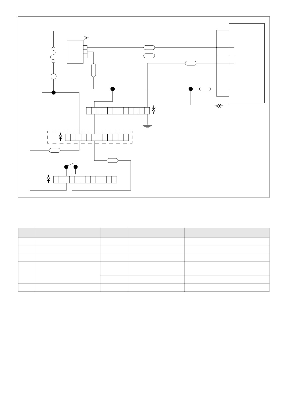
HOME
R/BK To Ignition Switch
Ignition Control Module
[83B]
7
A
Y \ BE
Rear Coil
B
6
C
BE \ O
Front Coil
5
15 Amp
BK
Ground
Ignition Fuse
W
Ignition
\
B
Coil
K
GY
1
W \ BK
Key ON Power
To TSM/TSSM
[10B]
[10A]
[8A]
To
1
2
3
4
5
6
7
8
9
10
11
12
[8B]
Data Link
Ground Stud
[1B]
1
2
3
4
5
6
7
8
9
10
11
12
[1A]
FLHT/C Only
GY
Engine Stop Switch
W \ BK
6-Place on FLHR/S
[22B]
1
2
3
4
5
6
7
8
9
10
11
12
[22A]
Figure 4-33. Battery Voltage Circuit
Table 4-24. Wire Harness Connectors in Figure 4-33.
NO.
DESCRIPTION
MODEL
TYPE
LOCATION
[1]
Main to Interconnect Harness
FLHT/C
12-Place Deutsch
Inner Fairing- Right Fairing Bracket
[8]
Ignition Harness
All
12-Place Deutsch
Under Right Side Cover
[10]
Ignition Control Module
All
12-Place Deutsch (Black)
Under Right Side Cover
Inner Fairing-
Interconnect to Right
FLHT/C
12-Place Deutsch
[22]
Right Fairing Support Brace
Handlebar Switch Controls
FLHR/S
6-Place Deutsch
Inside Headlamp Nacelle
[83]
Ignition Coil
All
3 - Place Packard
Below Fuel Tank (Left Side)
4-46
2005 Touring: Engine Management (Carbureted)
HOME
Test 4.16 (Part 1 of 2)
IGNITION COIL: DTC P1351, P1352, P1354, P1355
Disconnect connector [83].
Measure voltage on Terminal B
of coil. Equal to battery voltage
1
after key ON?
YES
NO
Use Breakout Box and test light for the
2
next inspection.
Repair open wire or
connection on W/BK wire.
Front coil codes: Check between ICM Pin
3
6 and ICM Pin 1.
Rear coil codes: Check between ICM Pin
7 and ICM Pin 1.
Does test lamp flash when engine is
cranked?
YES
NO
Measure coil resistance.
Replace ICM.
4
Reprogram and
Front coil codes: Check between
perform password learn.
coil Terminal B and Terminal C.
Rear coil codes: Check between
coil Terminal B and Terminal A.
Resistance 0.5-0.7 ohms?
YES
NO
Replace coil.
STOP
Go to Test 4.16
(Part 2 of 2).
Clear codes using speedometer self diagnostics.
See 4.5 SPEEDOMETER SELF DIAGNOSTICS.
Confirm proper operation with no check engine
lamp.
2005 Touring: Engine Management (Carbureted)
4-47
HOME
Test 4.16 (Part 2 of 2)
IGNITION COIL: DTC P1351, P1352, P1354, P1355
Continued from Test 4.16 (Part 1 of 2).
Using Breakout Box, measure resistance between
ICM and coil terminals as follows.
DTC
COIL
BREAK-
TERMINAL
OUT BOX
TERMINAL
P1351/
C
6
P1352
(BE/O wire)
P1353/
A
1
7
P1354
(Y/BE wire)
3
Resistance less than 0.5 ohms?
YES
NO
Perform 5.8 WIGGLE TEST
Repair open wire
to check for intermittents.
or connection.
Intermittents present?
YES
NO
Repair
Check for continuity to ground.
intermittent.
Front coil codes: Check
Breakout Box Pin 6.
Rear coil codes: Check
Breakout Box Pin 7.
Continuity present?
YES
NO
Repair short
Check for voltage.
to ground.
Front coil codes: Check
Breakout Box Pin 6.
Rear coil codes: Check
Breakout Box Pin 7.
Voltage present?
YES
NO
Repair short
Replace ICM.
to voltage.
Reprogram and
learn password.
Clear codes using speedometer self diagnostics.
See 4.5 SPEEDOMETER SELF DIAGNOSTICS.
Confirm proper operation with no check engine
lamp.
4-48
2005 Touring: Engine Management (Carbureted)
HOME
DTC P0371, P0372, P0374
4.17
GENERAL
f2256x8x
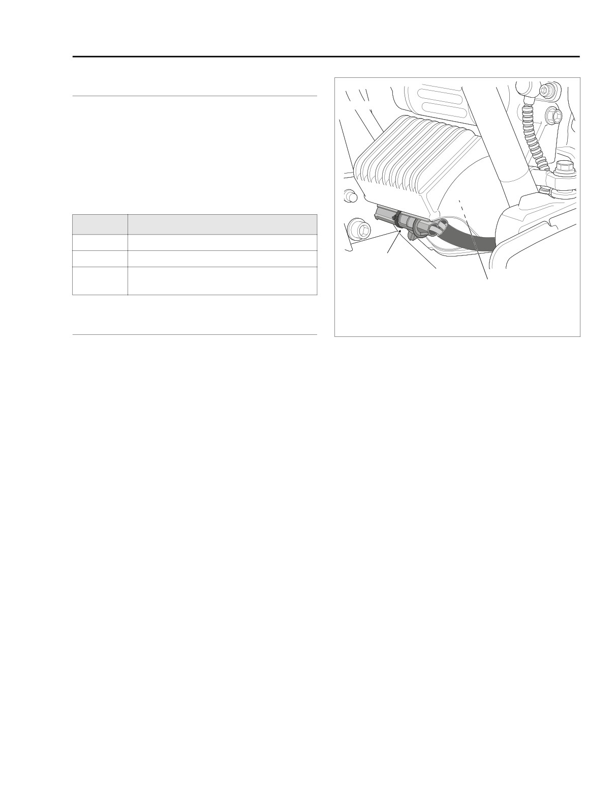
Crank Position Sensor
See Figure 4-34. A DTC P0371, P0372 and P0374 will set if
the crankshaft position sensor (CKP) signal is weak, shorted
or absent.
Table 4-25. Code Description
DTC
DESCRIPTION
P0371
Crankshaft position shorted low
P0372
Crankshaft position shorted high
Stator
Connector [46]
Crankshaft position sensor not detected/can-
P0374
not synchronize
Crankshaft
Position Sensor
Connector [79]
Under Voltage Regulator
DIAGNOSTICS
Figure 4-34. Voltage Regulator (Left Side View)
Diagnostic Notes
The reference numbers below correlate with the circled num-
bers on the Test 4.17 flow charts.
1. Connect BREAKOUT BOX (Part No. HD-42682) to igni-
tion control module wire harness only, leaving ignition
control module disconnected. See 4.6 BREAKOUT BOX:
ICM.
2. One megohm is very high resistance. Some meters will
read infinity, OL, etc.
3. Use HARNESS CONNECTOR TEST KIT (Part No. D-
41404A), brown socket probes and patch cords.
4. For testing purposes, install sensor without running wir-
ing along normal path. Disconnect and route wiring prop-
erly if system is now OK.
2005 Touring: Engine Management (Carbureted)
4-49
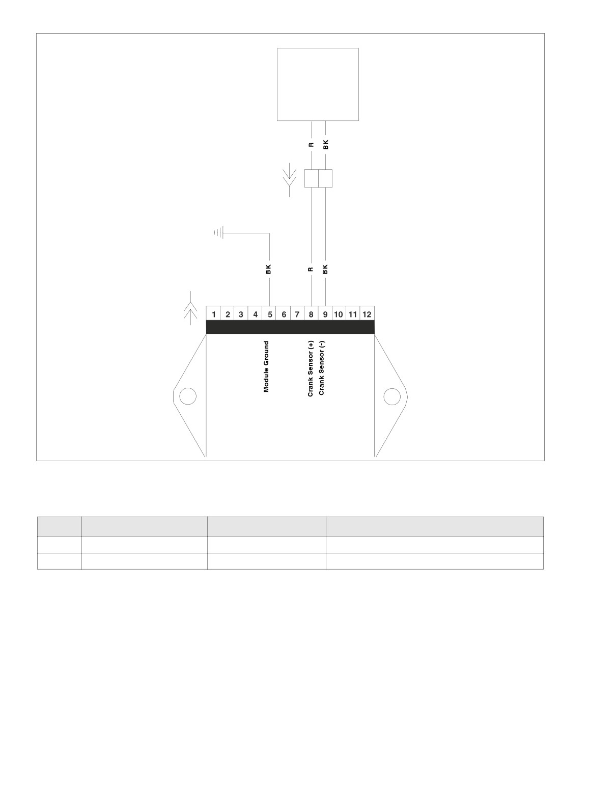
HOME
f2208w8x
Crankshaft
Position
Sensor
[79A]
[79B]
1
2
[10B]
[10A]
Ignition Control Module
Figure 4-35. Ignition Circuit
Table 4-26. Wire Harness Connectors in Figure 4-35.
NO.
DESCRIPTION
TYPE
LOCATION
[10]
Ignition Control Module
12-Place Deutsch
Under Right Side Cover
[79]
Crankshaft Position Sensor
2 - Place Mini-Deutsch
Bottom of Voltage Regulator
4-50
2005 Touring: Engine Management (Carbureted)
HOME
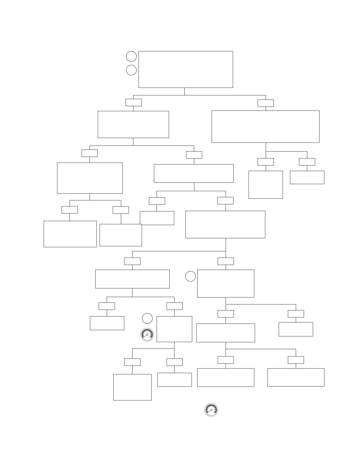
Test 4.17
CRANK POSITION SENSOR: DTC P0371, P0372,
P0374
Connect Breakout Box to harness only,
1
leaving ignition control module disconnected.
Measure resistance between Terminal 8 [10] and
Terminal 5 [10B] (black) on Breakout Box and
2
Terminal 9 [10] (black) and Terminal 5 of [10] (black)
on Breakout Box. Is resistance more than 1
megohm?
YES
NO
Measure voltage on Breakout Box
Disconnect connector [79]. Leaving ignition control module
between Terminal 8 [10] (+) and Termi-
disconnected, measure resistance between Terminal 8 and
nal 5 [10] (-) and also between Termi-
Terminal 5 [10B] (black) on Breakout Box. Also
nal 9 [10] (+) and Terminal 5 of [10] (-).
measure resistance between Terminal 9 [11B] (gray) and
Is voltage present?
Terminal 5 [10B] (black) on Breakout Box. Is there still
continuity to ground (less than 1 megohm resistance)?
YES
NO
YES
NO
Disconnect connector [79]. Measure
Check for intermittent connection, pinched
voltage on Breakout Box between
or damaged wires, and loose CKP sensor
Terminal 8 [10] (+) and Terminal 5
Repair short to
Replace CKP
fastener. Conditions found?
[10] (-) and also between Terminal 9
ground on R or
sensor.
[10] (+) and Terminal 5 of [10] (-).
BK wire between
Is voltage present?
connectors [10B]
and [79B].
YES
NO
YES
NO
Repair as
Connect DVOM to Terminals 8 and 9 at
necessary.
connector [10] on Breakout Box.
Locate and repair short to
Set DVOM to AC volts and crank engine.
voltage between red or black
Locate and repair
Does DVOM read 1 VAC minimum
wires between connector
short to voltage on
during cranking?
[79B] and connector [10B]
CKP sensor wires to
connector [79A].
at ICM.
YES
NO
With DVOM still connected, check for
Connect DVOM. At connector
intermittents using 4.7 WIGGLE TEST.
3
[79] Terminals 1 and 2, DVOM
Intermittents present?
should read 1 VAC
minimum while cranking.
Does it?
YES
NO
YES
NO
Repair as
4
Replace CKP sen-
necessary.
sor. Clear codes
Check for continuity between
Replace CKP
and retest. Code
sensor.
Terminal 8 [10B] and Terminal 1
P0371, P0372 or
[79B]. Is continuity present?
P0374 set?
YES
NO
YES
NO
Repair open on BK wire
Repair open on R wire between
System
between Terminal 2 [79B] and
Terminal 1 [79B] and Terminal
Reinstall CKP
sensor. Replace
OK.
Terminal 9 on connector [10B].
8 on connector [10B].
ICM. Reprogram
and perform pass-
word learn.
Clear codes using speedometer self diagnostics.
See 4.5 SPEEDOMETER SELF DIAGNOSTICS.
Confirm proper operation with no check engine
lamp.
2005 Touring: Engine Management (Carbureted)
4-51
HOME
DTC P0501, P0502
4.18
GENERAL
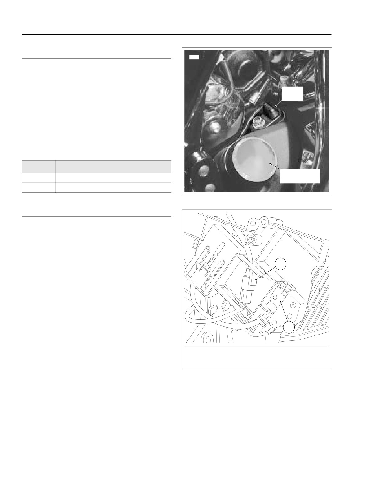
7951
Vehicle Speed Sensor
See Figure 4-36. The vehicle speed sensor is powered and
Speed
monitored by the ICM. The ICM processes the vehicle speed
Sensor
signal and transmits this signal to the TSM/TSSM and speed-
ometer through serial data.
NOTE
When the vehicle speed signal is greater than 0, the closed
loop idle speed control is inhibited.
Table 4-27. Code Description
DTC
DESCRIPTION
Engine Oil Fill
P0501
VSS sensor low
Plug/Dipstick
P0502
VSS sensor high/open
Figure 4-36. Vehicle Speed Sensor Location
DIAGNOSTICS
f2183x8x
Diagnostic Notes
The reference numbers below correlate with the circled num-
bers on the Test 4.18 flow charts.
1. The speedometer has a built-in diagnostic mode. See
1
4.5 SPEEDOMETER SELF DIAGNOSTICS.
2. Use HARNESS CONNECTOR TEST KIT (Part No. HD-
41404A), black pin probe and patch cord.
3. Connect BREAKOUT BOX
(Part No. HD-42682)
between wire harness and ICM. See 4.6 BREAKOUT
BOX: ICM.
4. Jack up motorcycle and rotate rear wheel with transmis-
2
sion in neutral.
1. Vehicle Speed Sensor Connector [65]
2. P&A Security Siren Connector [142]
Figure 4-37. Electrical Bracket (Inboard Side)
4-52
2005 Touring: Engine Management (Carbureted)
HOME
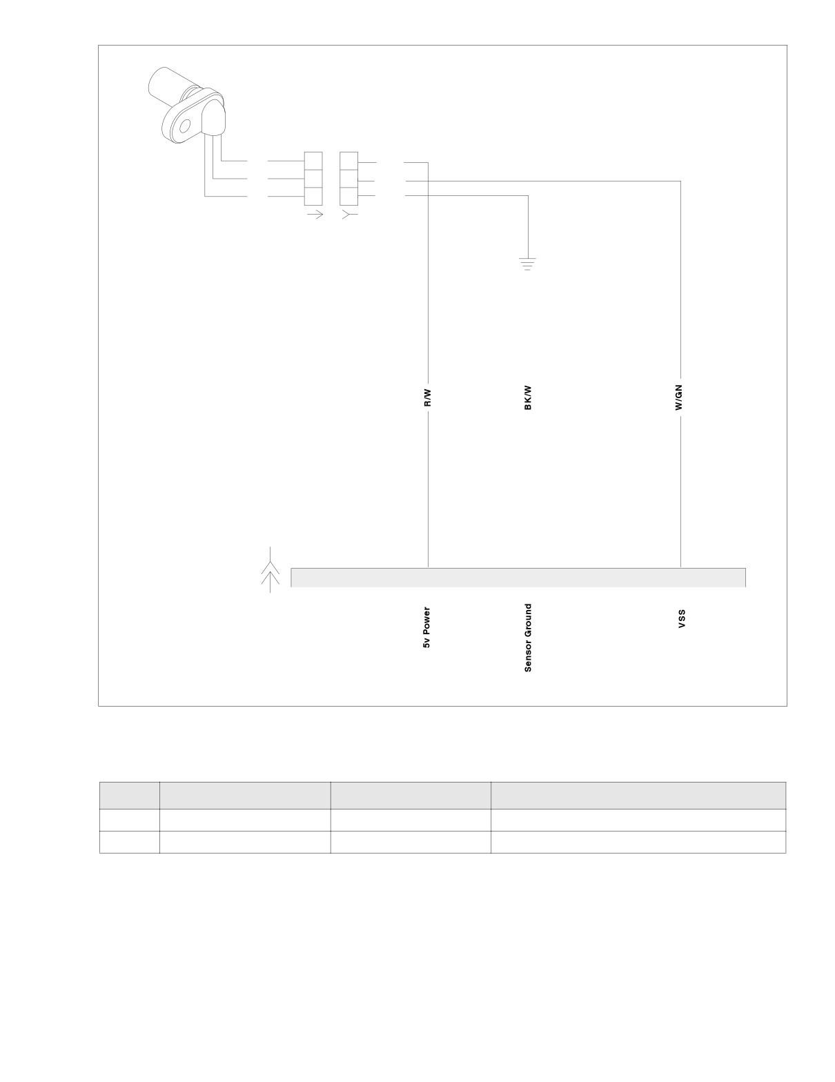
f2208x8x
Vehicle Speed
Sensor
R
R/W
A
A
W
B
B
W/GN
BK
C
C
BK/W
[65A]
[65B]
[10B]
3
10
[10A]
Ignition
Control
Module
Figure 4-38. Vehicle Speed Sensor Circuit
Table 4-28. Wire Harness Connectors in Figure 4-38.
NO.
DESCRIPTION
TYPE
LOCATION
[10]
Ignition Control Module
12-Place Deutsch
Under Right Side Cover
[65]
Vehicle Speed Sensor
3 - Place Deutsch
Under Right Side Cover (Behind Electrical Bracket)
2005 Touring: Engine Management (Carbureted)
4-53
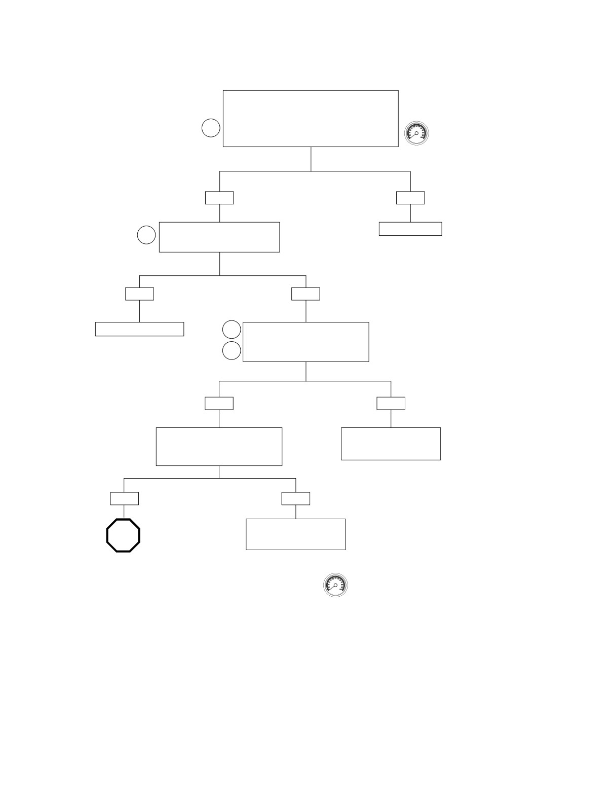
HOME
Test 4.18 (Part 1 of 2)
VEHICLE SPEED SENSOR: DTC P0501, P0502
Remove and inspect vehicle speed sensor. Inspect
for debris and clean if necessary. Place speedometer
into diagnostic mode and clear ICM trouble codes.
Connect all circuits and ride motorcycle for
1
approximately 1.0 mile (1.6 km). Check for newly
logged codes. Codes present?
YES
NO
Check for continuity between socket
System OK.
2
A of connector [65B] (R/W wire) and
ground. Continuity present?
YES
NO
Repair short to ground.
2
Check for continuity between socket A
of connector [65B] (R/W wire) and pin 3
[10] of breakout box. Continuity
3
present?
YES
NO
Check for continuity between socket C
Repair open on R/W wire
of connector [65B] (BK wire) and
between connectors [10B]
ground. Continuity present?
and [65B].
YES
NO
Repair open on BK wire
STOP
between connector [65B]
and ground.
Go to. Test 4.18
(Part 2 of 2)
Clear codes using speedometer self diagnostics.
See 4.5 SPEEDOMETER SELF DIAGNOSTICS.
Confirm proper operation with no check engine
lamp.
4-54
2005 Touring: Engine Management (Carbureted)
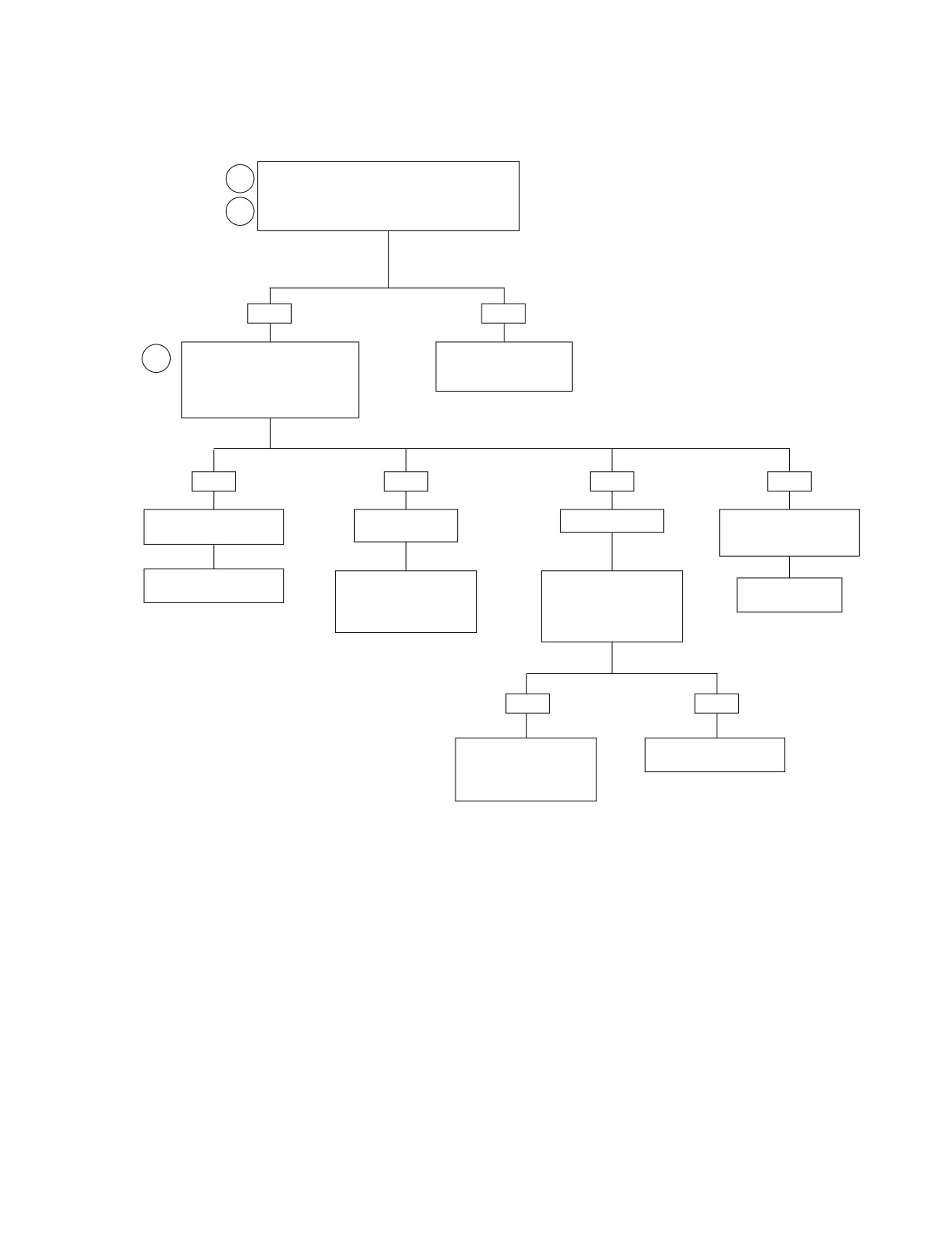
HOME
Test 4.18 (Part 2 of 2)
VEHICLE SPEED SENSOR: DTC P0501, P0502
Continued from Test 4.18 (Part 1 of 2).
2
Check for continuity between socket B of connector
[65B] and Pin 10 [10] of breakout box. Continuity
3
present?
YES
NO
Check for voltage at terminal 10
Repair open on W/GN
4
(black) on breakout box. Meter
wire between connectors
should read 4-6 volts when gear
[10B] and [65B].
tooth absent and 0-1 volts when
gear tooth is present. Does it?
YES
NO
NO
NO
Voltage fluctuates from high
Battery voltage
No voltage present.
No voltage fluctuation from
(4-6 Volts) to low (0-1 volts).
present.
high (4-6 volts) to low (0-1
volts).
Replace ICM. Reprogram
Locate and repair short to
Measure continuity to
Replace vehicle
and learn password.
voltage on W/GN wire
ground from terminal 10
speed sensor.
between connectors [10B]
(black) on breakout box. Is
and [65B].
resistance less than 100
ohms?
YES
NO
Locate and repair short to
Replace ICM. Reprogram
ground on W/GN wire
and learn password.
between connectors [10B]
and [65B].
2005 Touring: Engine Management (Carbureted)
4-55
HOME
DTC P0602, P0603, P0604, P0605, P0607
4.19
GENERAL
DIAGNOSTICS
ICM Failure
DTC P0607 Test
All of the following codes indicate an internal failure which
1.
Power down the vehicle.
requires replacement of the ignition control module. See the
2.
Clear codes using speedometer self-diagnostics.
Touring Service Manual for replacement procedures.
3.
Replace ICM if codes reappear.
● DTC P0602 - Calibration memory error
● DTC P0603 - EE PROM failure
● DTC P0604 - RAM failure
DTC P0602, P0603, P0604, P0605 Test
● DTC P0605 - Program memory error
1.
Power down the vehicle.
● DTC P0607 - A to D converter error
2.
Clear codes.
3.
Using Digital Technician, reprogram ICM using the cor-
rect calibration. See your dealer.
4.
Restart vehicle. If code reappears, replace ICM. Repro-
gram and perform password learn.
4-56
2005 Touring: Engine Management (Carbureted)
HOME
DTC U1064
4.20
GENERAL
Loss of TSM/TSSM Serial Data
The serial data connector provides a means for the ICM and
TSM/TSSM to communicate their current status. When all
operating parameters on the serial data link are within specifi-
cations, a state of health message is sent between the com-
ponents. A DTC U1064 indicates that the TSM/TSSM is not
receiving this state of health message.
Table 4-29. Code Description
DTC
DESCRIPTION
U1064
Loss of TSM/TSSM serial data
f2323x8x
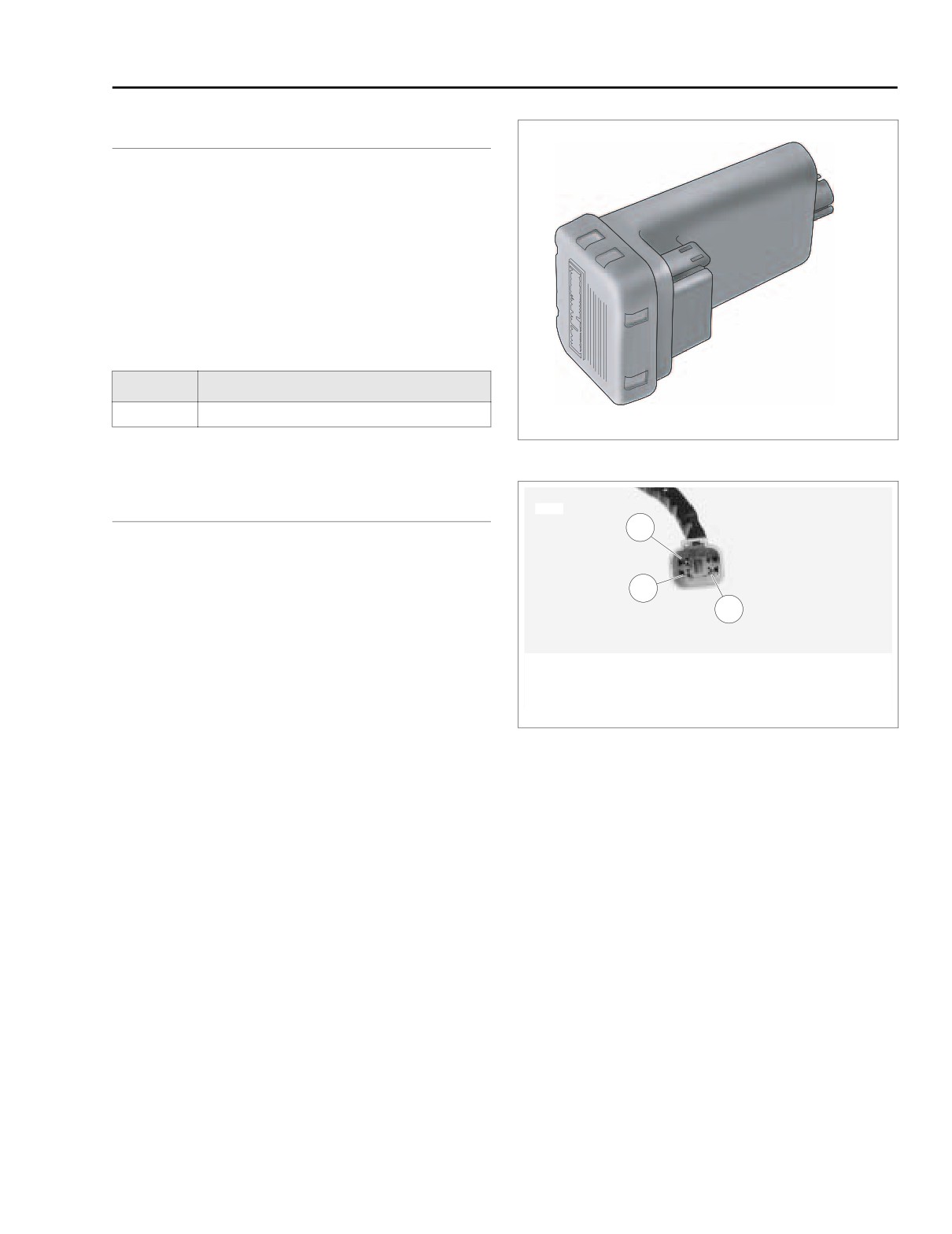
Figure 4-39. TSM/TSSM
DIAGNOSTICS
6924c
3
Diagnostic Notes
The reference numbers below correlate with the circled num-
2
bers on the Test 4.20 flow chart.
1
1.
Connect BREAKOUT BOX (Part No. HD-42682) as fol-
lows:
1. Terminal 2: ground (BK)
a. Mate black socket housing on Breakout Box with
2. Terminal 3: serial data (Lt GN/V)
speedometer connector [39] using SPEEDOMETER
3. Terminal 4: power (GY)
HARNESS ADAPTER (Part No. HD-46601).
b. Mate black pin housing on Breakout Box with speed-
Figure 4-40. Data Link Connector
ometer harness connector [39B] using SPEEDOM-
ETER HARNESS ADAPTER (Part No. HD-46601).
c. Mate gray socket housing on Breakout Box with
TSM/TSSM connector [30A].
d. Mate gray pin housing on Breakout Box with har-
ness connector [30B].
2005 Touring: Engine Management (Carbureted)
4-57
HOME
f2332e8x
[156B] [156A]
Main to Interconnect
6
6
Harness
5
5
4
4
3
3
GY
BK
2
2
BK
LtGN/V
1
1
LtGN/V
O
1
2
3
4 5 6 7 8 9 10 11 12
[30B]
BN/GY
1
2
3
4 5 6 7 8 9 10 11 12
[30A]
TSM/TSSM
BN/GY
[39B]
GY
BK
1
2
3
4 5 6 7 8 9 10 11 12
[39A]
1
2
3
4 5 6 7 8 9 10 11 12
1
2
3
4 5 6 7 8 9 10 11 12
[8B]
Speedometer
1
2
3
4 5 6 7 8 9 10 11 12
1
2
3
4 5 6 7 8 9 10 11 12
[8A]
[108B]
1
2
3
4 5 6 7 8 9 10 11 12
Ignition
To
[108A]
Harness
Ignition
Tachometer
Keyswitch
Relay
15A
Instruments
[1B] [1A]
Fuse
1
2
Main to Interconnect
3
[2A]
1
2
3
4 5 6 7 8 9 10 11 12
Harness
4
Data Link
[2B]
1
2
3
4 5 6 7 8 9 10 11 12
[91A]
Main to Interconnect
15A
Harness
Ignition
Fuse
12
15A
[10B]
Battery
12
[10A]
Ignition Control Module
Fuse
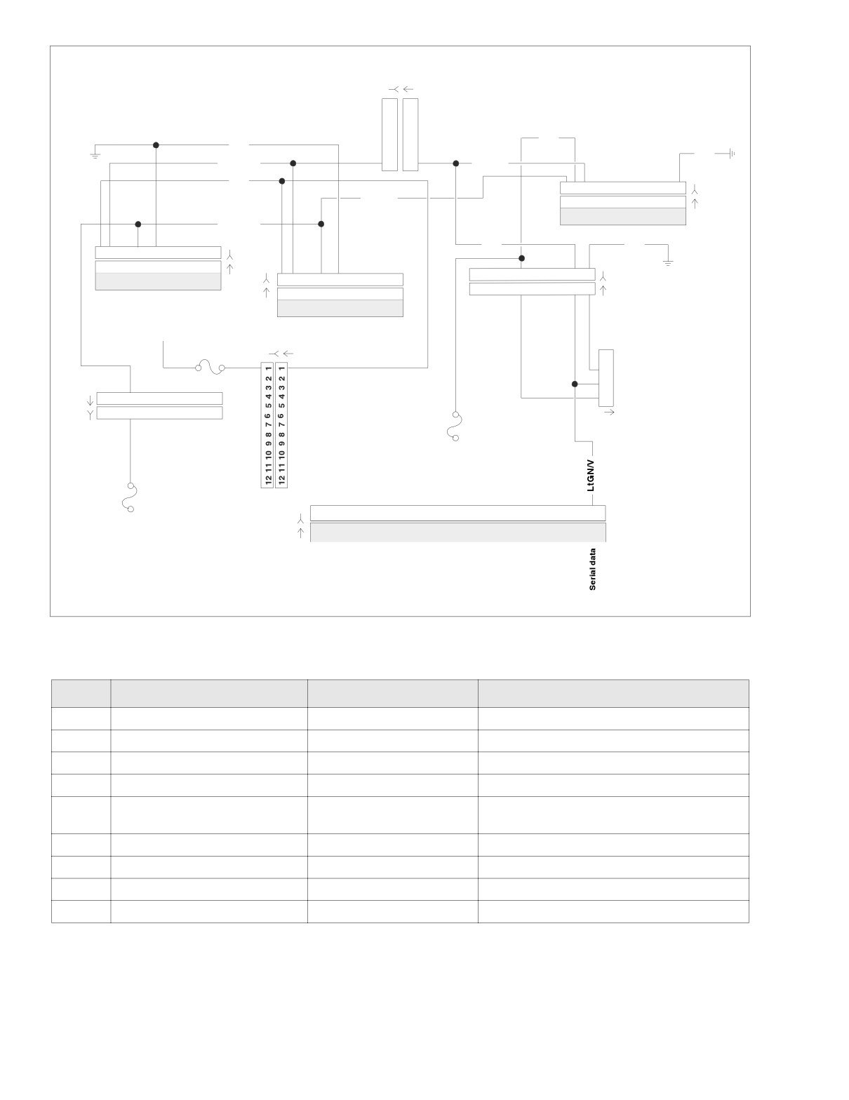
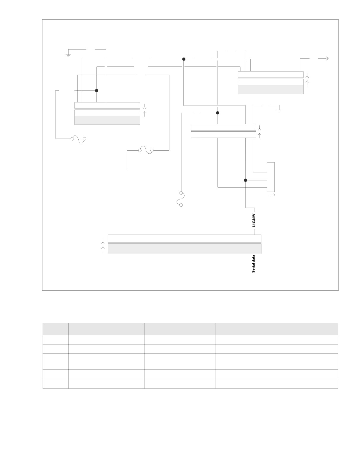
Figure 4-41. Serial Data Circuit (FLHT/C)
Table 4-30. Wire Harness Connectors in Figure 4-41.
NO.
DESCRIPTION
TYPE
LOCATION
[1]
Main to Interconnect Harness
12-Place Deutsch (Black)
Inner Fairing - Right Radio Support Bracket
[2]
Main to Interconnect Harness
12-Place Deutsch (Gray)
Inner Fairing - Right Fairing Support Brace
[8]
Ignition Harness
12-Place Deutsch
Under Right Side Cover
[10]
Ignition Control Module
12-Place Deutsch
Under Right Side Cover
Cavity in Crossmember at Rear of
[30]
Turn Signal/Security Module
12-Place Deutsch
Battery Box (Under Seat)
[39]
Speedometer
12-Place Packard
Inner Fairing (Back of Speedometer)
[91]
Data Link
4-Place Deutsch
Under Right Side Cover
[108]
Tachometer
12-Place Packard
Inner Fairing (Back of Tachometer)
[156]
Main to Interconnect Harness
6-Place Deutsch
Inner Fairing - Right Fairing Support Brace
4-58
2005 Touring: Engine Management (Carbureted)
HOME
f2332d8x
BK
GY
LtGN/V
LtGN/V
BK
BN/GY
O
1
2
3
4
5 6 7 8 9 10 11 12
[30B]
1
2
3
4
5 6 7 8 9 10 11 12
[30A]
BN/GY
TSM/TSSM
BK
1
2
3
4 5 6 7 8 9 10 11 12
[39B]
1
2
3
4 5 6 7 8 9 10 11 12
[39A]
GY
Speedometer
1
2
3
4
5
6
7
8
9
10 11 12
[8B] Ignition
15A
1
2
3
4
5
6
7
8
9
10 11 12
[8A] Harness
Instruments
Fuse
15A
Battery
Fuse
1
To
2
Ignition
Keyswitch
3
Relay
4
Data Link
[91A]
15A
Ignition
Fuse
12
[10B]
[10A]
Ignition Control Module
12
Figure 4-42. Serial Data Circuit (FLHR/S)
Table 4-31. Wire Harness Connectors in Figure 4-42.
NO.
DESCRIPTION
TYPE
LOCATION
[8]
Ignition Harness
12-Place Deutsch
Under Right Side Cover
[10]
Ignition Control Module
12-Place Deutsch
Under Right Side Cover
Cavity in Crossmember at Rear of
[30]
Turn Signal/Security Module
12-Place Deutsch
Battery Box (Under Seat)
[39]
Speedometer
12-Place Packard
Under Console (Back of Speedometer)
[91]
Data Link
4-Place Deutsch
Under Right Side Cover
2005 Touring: Engine Management (Carbureted)
4-59
HOME
Test 4.20
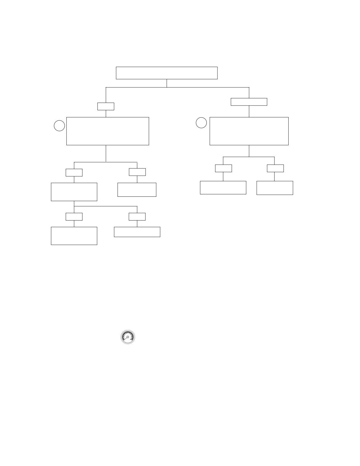
LOSS OF TSM/TSSM SERIAL DATA: DTC U1064
Can you read TSM/TSSM hardware P/N?
See 4.5 SPEEDOMETER SELF DIAGNOSTICS.
NO or “No Rsp”
YES
Install Breakout Box on speedometer.
Install Breakout Box on speedometer.
1
1
While wiggling harness, check for continuity
Check for continuity between terminal 3
between terminal 3 (gray) and terminal 2
(gray) and terminal 2 (black) of Breakout
(black) of Breakout Box
Box
Continuity present?
Continuity present?
YES
NO
YES
NO
Replace TSM/TSSM.
Repair open on
Clear trouble codes.
Repair intermittent
Learn password.
LtGN/V wire.
Test Ride. Does U1064
on LtGN/V wire.
return?
YES
NO
Replace TSM/TSSM.
No trouble found.
Perform password learn
procedure.
Clear codes using speedometer self diagnostics.
See 4.5 SPEEDOMETER SELF DIAGNOSTICS.
Confirm proper operation with no check engine
lamp.
4-60
2005 Touring: Engine Management (Carbureted)
HOME
DTC U1097
4.21
GENERAL
f2191x8x
Loss of Speedometer Serial Data
The serial data connector provides a means for the speedom-
eter, ICM and TSM/TSSM to communicate their current sta-
tus. When all operating parameters on the serial data link are
within specifications, a state of health message is sent
between the components. A DTC U1097 indicates that the
speedometer is not capable of sending this state of health
message.
Table 4-32. Code Description
DTC
DESCRIPTION
Loss of all speedometer serial data
U1097
(state of health)
Ignition Control Module
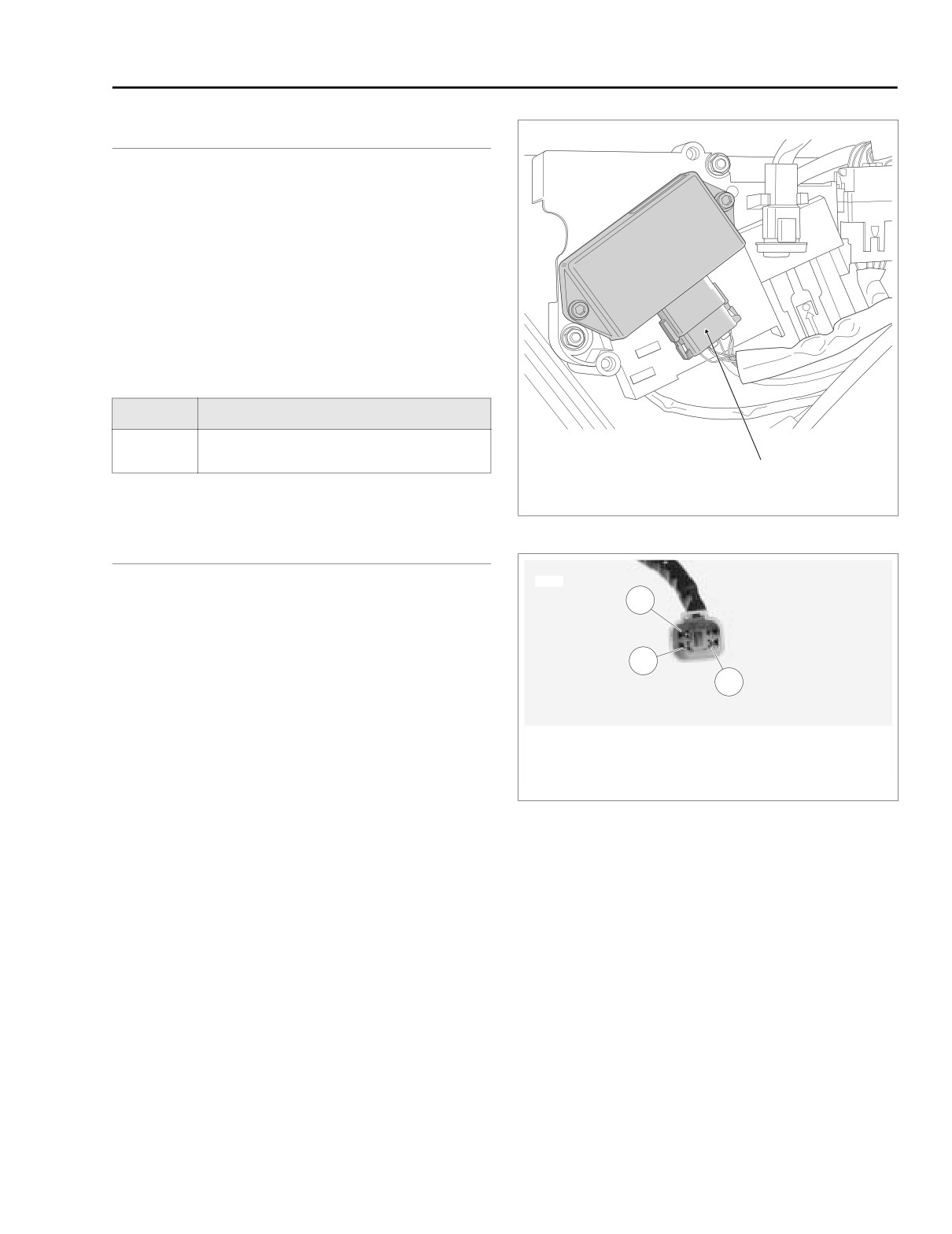
Connector [10]
Figure 4-43. Electrical Bracket (Under Right Side Cover)
DIAGNOSTICS
6924c
Diagnostic Notes
3
The reference numbers below correlate with the circled num-
bers on the 4.21 flow chart.
2
1. Connect BREAKOUT BOX (Part No. HD-42682) (black)
1
to wire harness connector [39B] using SPEEDOMETER
HARNESS ADAPTER (Part No. HD-46601). Leave
speedometer connector [39A] disconnected. See
2.5
1. Terminal 2: ground (BK)
BREAKOUT BOX: SPEEDOMETER.
2. Terminal 3: serial data (Lt GN/V)
3. Terminal 4: power (GY)
2. Use HARNESS CONNECTOR ADAPTER KIT (Part No.
HD-41404A), black pin probe and patch cord.
Figure 4-44. Data Link Connector
2005 Touring: Engine Management (Carbureted)
4-61