Harley Davidson 2005 touring models. Service repair manual - page 16
HOME
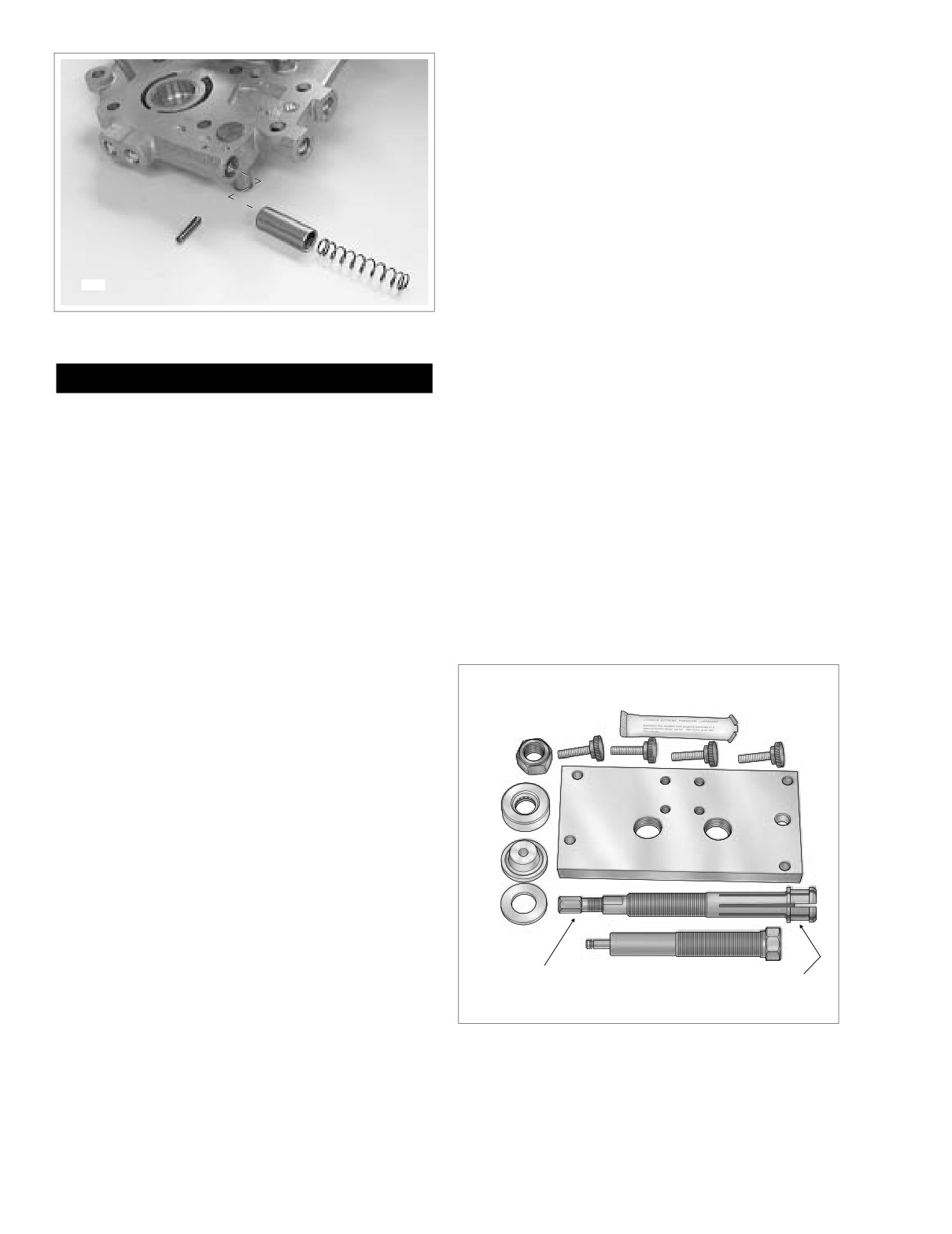
3. Slide spring into bypass port until seated in open side of
piston.
4. Start new roll pin into hole in cam support plate. Com-
press spring using the blade of a small screwdriver.
5. Holding spring compressed, tap roll pin into cam support
plate until it approaches pin hole on opposite side.
6. Remove screwdriver to release spring. Verify that spring
is straight and square in bore.
7. Using a 1/8 inch punch with a small hammer, carefully
tap roll pin until flush with casting.
6908
8. Install primary cam chain tensioner assembly. See CAM
CHAIN TENSIONERS, INSTALLATION, in this section.
Figure 3-116. Oil Pressure Relief Valve Assembly
Cam Needle Bearings
1WARNING
Removal
Always wear proper eye protection when installing re-
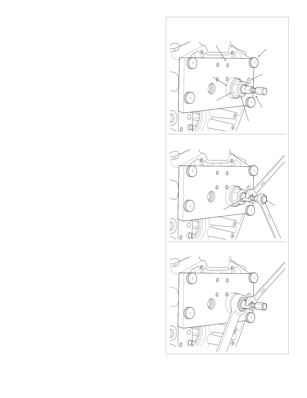
1. Obtain the CAMSHAFT NEEDLE BEARING RE-
taining rings. Use the correct retaining ring pliers. Verify
MOVER/INSTALLER (HD-42325).
that the tips of the pliers are not damaged or excessively
worn. Slippage may propel the ring with enough force to
2. Remove four button fasteners from threaded holes in
support plate, if installed. See Figure 3-117.
cause eye injury.
2. With the sharp edge out, install new retaining ring in
3. Sparingly apply graphite lubricant to threads of collet to
groove of post. Verify that the ring is fully seated in the
prolong service life and ensure smooth operation.
groove.
4. Slide collet through support plate so that threaded end
3. If retracted prior to disassembly, place cup of CAM
exits stamped side of plate.
CHAIN TENSIONER UNLOADER
(HD-42313) over
5. Aligning two large holes in support plate with needle
spring coil of cam chain tensioner assembly. Retract the
bearing bores, hang right side of plate on ring dowel in
tensioner inserting a retention pin through hole in boss
crankcase flange.
on the primary cam chain side of cam support plate.
Oil Pressure Relief Valve
f1303x2x
Graphite
Lubricant
Removal
Button
1. Before removal, see CLEANING AND INSPECTION in
Hex Nut
Fastener (4)
this section.
Nice
2. Remove primary cam chain tensioner assembly. See
Bearing
CAM CHAIN TENSIONERS, REMOVAL.
Support
Plate
3. Secure the cam support plate in a vise with access to
the roll pin. Be sure to install a pair of brass jaw inserts in
the vise to avoid damage to the casting.
Pilot
4. Using a 1/8 inch punch with a small hammer, carefully
tap roll pin from pin hole in cam support plate. Discard
roll pin.
5. Remove spring and piston from bypass port.
Flat
Washer
Installation
Installer
Collet
1.
Secure the cam support plate in a vise. Install a pair of
Shaft
Collet
Threaded End
Expandable End
brass jaw inserts to avoid damage to the casting.
2.
Lubricate piston with clean H-D 20W50 engine oil. Slide
piston into bypass port with the open side facing out-
Figure 3-117. Camshaft Needle Bearing Remover/Installer
(HD-42325)
ward.
3-96
2005 Touring: Engine
HOME
6.
Align four holes at corners of support plate with threaded
Install support plate with collet.
holes in crankcase flange. Install button fasteners in
Install Nice bearing, flat washer and hex nut.
these holes to secure support plate to crankcase. See
upper frame of Figure 3-118.
Support
Button
7.
Center expandable end of collet in bearing bore and
Plate
Fastener
slide Nice bearing and flat washer on threaded end.
Start hex nut on threaded end.
8.
Push expandable end of collet through bearing bore into
flywheel compartment. Feel for inside edge of needle
Nice
Ring Dowel
bearing using end of collet and then back off slightly.
Bearing
Hole
9.
Holding collet to prevent lateral movement, finger tighten
hex nut until Nice bearing contacts support plate.
10.
Using a 7/16 inch open end wrench, hold flat on collet to
prevent rotation. Using a second 7/16 inch open end
Flat
wrench, expand collet by turning hex at end of shaft in a
Washer
clockwise direction. See center frame of Figure 3-118.
Collet
Expandable end of collet makes contact with needle
Threaded End
bearing ID.
Hex
11.
Using a 15/16 inch open end wrench, turn hex nut in a
Nut
f1586x3x
clockwise direction until bearing is free. If necessary,
hold flat on collet to prevent rotation. See lower frame of
Holding flat, turn hex in a
f1587x3x
Figure 3-118.
clockwise direction to expand collet.
12.
Remove four button fasteners and pull support plate
from crankcase.
13.
Holding flat on collet, turn hex at end of shaft in a coun-
terclockwise direction to close collet. Remove and dis-
card needle bearing.
14.
Remove hex nut, flat washer and Nice bearing from
threaded end of collet. Pull collet from support plate.
15.
Return to step 1 to remove second needle bearing.
Installation
Hex
Flat
1.
Obtain the CAMSHAFT NEEDLE BEARING RE-
MOVER/INSTALLER (HD-42325).
2.
Sparingly apply graphite lubricant to threads of installer
shaft to prolong service life and ensure smooth opera-
tion.
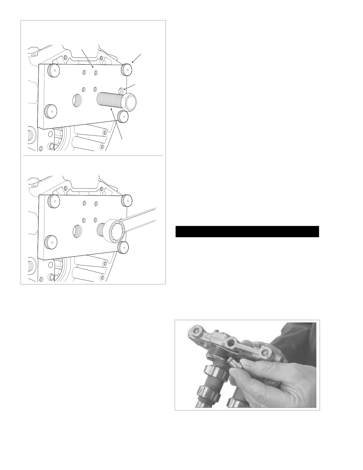
3.
Thread installer shaft into stamped side of support plate
Turn hex nut in a clockwise direction
to remove bearing.
until threads begin to emerge from opposite side.
4.
Install pilot at end of installer shaft.
5.
Place new needle bearing on pilot with lettered side fac-
ing shoulder.
6.
Aligning two large holes in support plate with needle
bearing bores, hang right side of plate on ring dowel in
crankcase flange.
7.
Align four holes at corners of support plate with threaded
holes in crankcase flange. Install button fasteners in
these holes to secure support plate to crankcase. See
upper frame of Figure 3-119.
8.
Using 15/16 inch open end wrench, turn hex at end of
installer shaft in a clockwise direction until resistance is
felt. See lower frame of Figure 3-119.
9.
Turn end of installer shaft in a counterclockwise direction
until pilot is free of needle bearing bore.
f1588x3x
Figure 3-118. Remove Cam Needle Bearing
2005 Touring: Engine
3-97
HOME
a. Measure distance from edge of cam support plate
Install support plate with installer shaft (and pilot).
to inboard side of piston. Insert straight stiff wire into
unplugged hole outboard of roll pin until it bottoms,
Support
and then mark and measure wire. With piston fully
Plate
Button
seated in the bore, depth should be approximately
Fastener
2.25 inches (57.15 mm). If it is not, continue with
step 1(b).
b. Remove oil pressure relief valve. See OIL PRES-
SURE RELIEF VALVE, REMOVAL, in this section.
Ring Dowel
c. Inspect spring for stretching, kinking or distortion.
Hole
d. Inspect piston and bore for burrs, scoring or other
damage. Look for steel particles or aluminum chips.
Replace cam support plate and piston if any of
these conditions are found.
e. Install piston in bore and measure running clear-
ance. If running clearance exceeds
0.003 inch
(0.076 mm), install new piston and remeasure.
Replace cam support plate if running clearance still
Installer
exceeds specification.
Shaft
f1589x3x
2.
Clean cam support plate as follows:
Turn hex on installer shaft in a clockwise direction
to install bearing.
a. Using a small screwdriver, carefully pry cleaning
plug from cam support plate. See Figure 3-120.
b. Thoroughly flush cam support plate with a non-vola-
tile cleaning solution or solvent and then blow dry
with low pressure compressed air.
c. Reinstall cleaning plug replacing O-ring if damaged
or deteriorated.
d. Verify that all oil holes are clean and open.
CAUTION
Exercise caution to avoid enlarging the oil holes or oil
pressure will be adversely affected.
Installation
f1590x3x
1.
See Section 3.10 BOTTOM END OVERHAUL, ASSEM-
BLY, steps 12-29.
Figure 3-119. Install Cam Needle Bearing
2.
Remove wireforms to release hydraulic lifters.
3.
See Section 3.9 TOP END OVERHAUL, ASSEMBLY,
steps 29-39.
10.
Remove four button fasteners and pull support plate and
installer shaft from crankcase.
11.
Remove pilot from installer shaft. Unthread installer
shaft from support plate.
12.
Return to step 1 to install second needle bearing.
13.
Thread four button fasteners into threaded holes in sup-
port plate to prevent loss.
Cleaning and Inspection
1.
Inspect oil pressure relief valve as follows:
NOTE
If diagnosing low oil pressure, start with step 1(a). If diagnos-
6891
ing high oil pressure, then begin with step 1(b).
Figure 3-120. Remove Cleaning Plug
3-98
2005 Touring: Engine
HOME
OIL PUMP
Inner Gerotor
Outer Gerotor
Removal
1. See Section 3.9 TOP END OVERHAUL, DISASSEM-
BLY, steps 1-11.
NOTE
When removing the cam support plate, it is not necessary to
disturb the lifter assemblies if a method is devised to prevent
the hydraulic lifters from dropping into the cam compartment.
Wear
One such method is provided in the following step. Leaving
Limit
the lifter assemblies intact simplifies the procedure, since the
lifter cover, gasket, anti-rotation pin and hydraulic lifters can
be left in place.
f1563x3x
2. Fashion lifter holding tool as follows:
a. Obtain a large binder clip (available at any office
Figure 3-122. Measure Gerotor Sets for Wear
supply store). Squeeze wireforms to remove from
binder clip. See upper frame of Figure 3-101.
b. Compress wireform slightly and insert free ends into
2.
Thoroughly dry all parts with low pressure compressed
outer and inner lifter cover bores so that legs
air. Verify that all oil passages are clean and open.
engage walls of both hydraulic lifter sockets. See
3.
Look for scoring, gouging or cracking caused by foreign
lower frame of Figure 3-101.
material that may have passed through the oil pump.
3. See Section 3.10 BOTTOM END OVERHAUL, DISAS-
4.
Look for grooves or scratches on the cam support plate,
SEMBLY, steps 1-15.
which serves as the outboard side of the oil pump.
5.
Check for excessive wear or damage on lobes of outer
Cleaning and Inspection
gerotors and between lobes on inner gerotor.
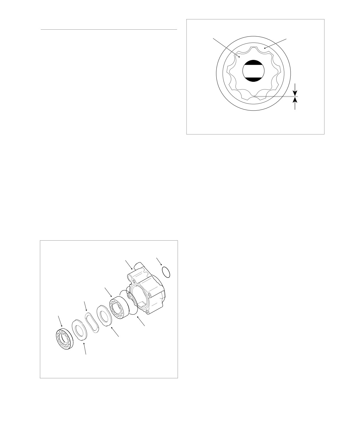
6.
Mesh pieces of one gerotor set together as shown in
1. Clean all parts in a non-volatile cleaning solution or sol-
Figure 3-122. Use a feeler gauge to determine clear-
vent.
ance between tips of lobes on inner and outer gerotors.
The maximum allowable clearance is
0.004 inch
(0.10 mm). Replace gerotor set if clearance exceeds
specification. Inspect second gerotor set in the same
Oil Pump
O-Ring
manner.
Housing
7.
Measure thickness of inner gerotor of one set with a
micrometer. Measure the outer gerotor of the same set.
Wide
Replace the gerotor set if the difference exceeds 0.001
Gerotor Set
inch (0.025 mm). Inspect second gerotor set in the same
(Scavenge)
manner.
Wave
8.
Assemble the oil pump. Verify that feed gerotors stand
Washer
Narrow
proud of the oil pump surface
0.0215-0.0305 inch
Gerotor Set
(0.546-0.775 mm). If measurement is less than 0.0215
(Feed)
inch (0.546 mm), remove feed gerotor set and reassem-
ble using new wave washer. Repeat measurement and
replace oil pump body if still not within specification.
O-Ring
Separator
Plate
Installation
1.
See Section 3.10 BOTTOM END OVERHAUL, ASSEM-
Separator
BLY, steps 11-29.
Plate
f1530b3x
2.
Remove wireforms to release hydraulic lifters.
3.
See Section 3.9 TOP END OVERHAUL, ASSEMBLY,
Figure 3-121. Oil Pump Assembly
steps 29-39.
2005 Touring: Engine
3-99
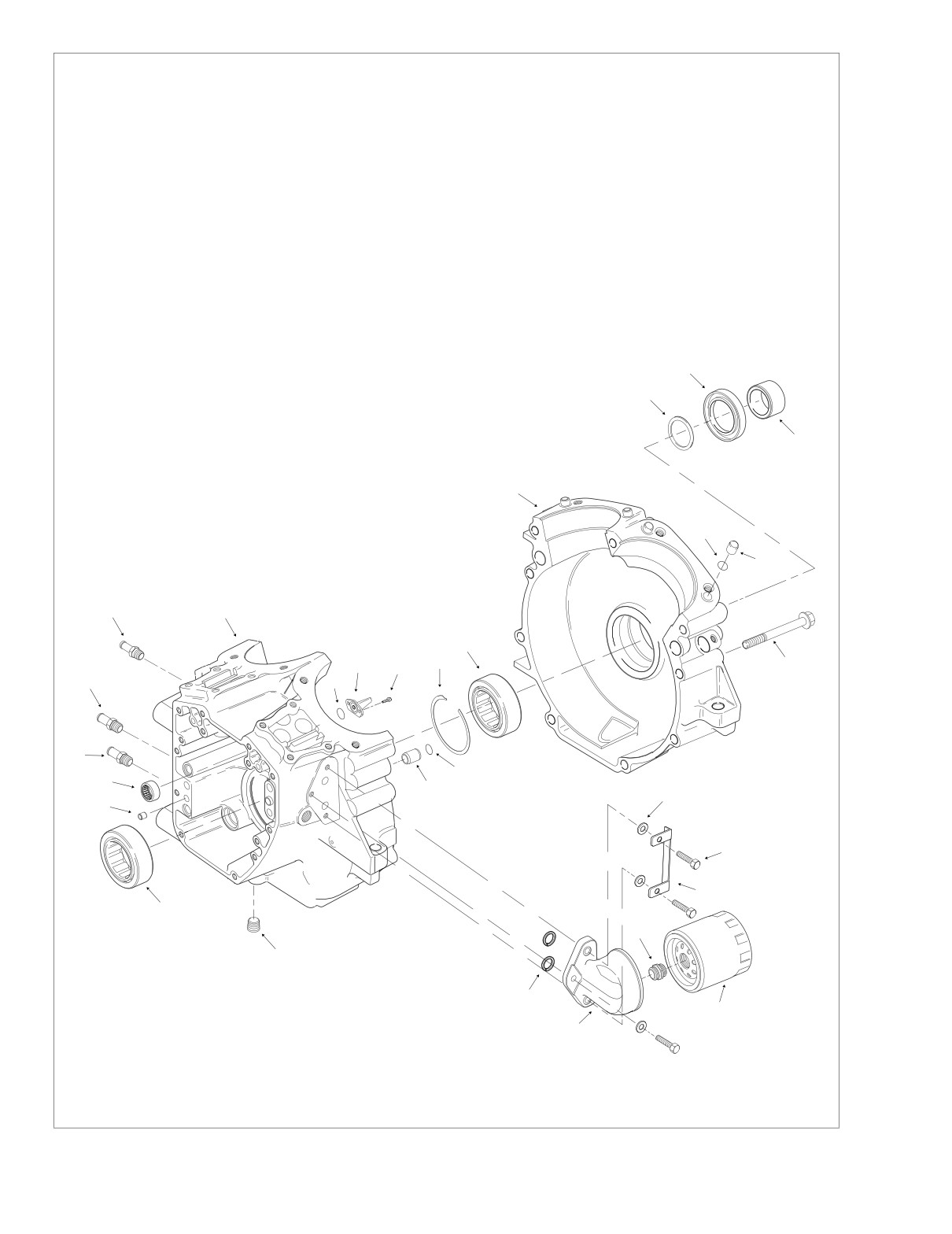
HOME
Legend:
f2070x3x
1.
Crankshaft Bearing
2.
Ring Dowel
3.
Cam Needle Bearing
4.
Oil Inlet Fitting
5.
Oil Outlet Fitting
6.
Crankcase Breather Fitting
7.
Right Crankcase Half
8.
O-Ring
9.
Piston Jet
10.
T20 TORX Screw
11.
Lock Ring
12.
Sprocket Shaft Bearing
13.
O-Ring
14.
Ring Dowel
15.
Plug
16.
O-Ring
17.
Oil Filter Mount
18.
Oil Filter Adapter
19.
Flat Washer
20.
Bolt
28
21.
Lockplate
22.
Oil Filter
27
23.
Crankcase Bolt
24.
Ring Dowel
25.
O-Ring
26.
Left Crankcase Half
29
27.
Thrust Washer
28.
Oil Seal
29.
Sprocket Shaft Spacer
26
25
24
6
7
12
11
23
9
10
5
8
4
13
3
14
19
2
20
21
1
18
15
16
22
17
Figure 3-123. Crankcase Assembly (Exploded View)
3-100
2005 Touring: Engine
HOME
CRANKCASE
3
1.
Ram
2.
Pilot/Driver
Removal
3.
Support Tube
1. See Section 3.9 TOP END OVERHAUL, DISASSEM-
BLY, steps 1-29.
“A”
End Up
2. See Section 3.10 BOTTOM END OVERHAUL, DISAS-
SEMBLY, steps 1-18.
1
f2126x3x
Disassembly/Assembly
2
RIGHT CRANKCASE HALF
Crankshaft Bearing
Removal
1CAUTION
Never move or lift the crankcase by grasping the cylin-
der studs. The crankcase is too heavy to be carried in
this manner and may be dropped. Dropping the crank-
case may result in parts damage and minor or moderate
injury.
1.
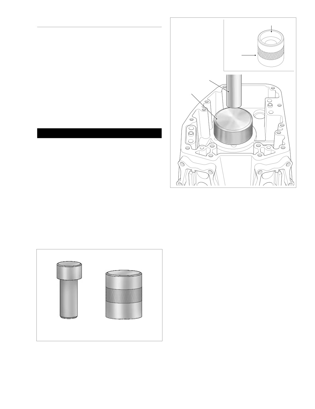
See Figure 3-124. Obtain CRANKSHAFT/SPROCKET
SHAFT BEARING REMOVER/INSTALLER PILOT/
DRIVER
(B-45655) and CRANKSHAFT/SPROCKET
SHAFT BEARING REMOVER/INSTALLER SUPPORT
Figure 3-125. Remove Crankshaft Bearing
TUBE (HD-42720-5).
2.
Place support tube on hydraulic press table with the “A”
4.
Slide pilot/driver through bearing into support tube.
end up. The ends of the support tube are stamped “A”
and “B” to ensure proper orientation.
5.
Center pilot/driver under ram of press. Apply pressure to
3.
With the outboard side of the right crankcase half facing
pilot/driver until bearing is free. See Figure 3-125.
upward, position crankshaft bearing bore over support
6.
Remove right crankcase half, pilot/driver and bearing
tube.
from support tube. Discard bearing.
Support Tube
Installation
Part No. HD-42720-5
1.
See Figure 3-124. Obtain CRANKSHAFT/SPROCKET
SHAFT BEARING REMOVER/INSTALLER PILOT/
DRIVER
(B-45655) and CRANKSHAFT/SPROCKET
SHAFT BEARING REMOVER/INSTALLER SUPPORT
TUBE (HD-42720-5).
2.
Turn support tube over so that the “B” end is up. The
ends of the support tube are stamped “A” and “B” to
ensure proper orientation.
3.
With the outboard side of the right crankcase half facing
Pilot/Driver
upward, position crankshaft bearing bore over support
Part No. B-45655
d0687x3x
tube.
4.
Obtain new crankshaft bearing and apply a thin film of
Figure 3-124. Crankshaft/Sprocket Shaft Bearing
clean engine oil to O.D.
Pilot/Driver and Support Tube
2005 Touring: Engine
3-101
HOME
Installation
3
1. Ram
2. Pilot/Driver
CAUTION
3. Support Tube
4. Crankshaft Bearing
O-rings that are missing, distorted, pinched or otherwise
“B”
damaged will result in either oil leakage or low oil pres-
End Up
sure. Use of the wrong O-ring will have the same results.
Since many O-rings are similar in size and appearance,
always use new O-rings keeping them packaged until
1
use to avoid confusion.
f2127x3x
2
1.
Install new O-ring in groove of jet mounting flange. Apply
a very thin film of clean H-D 20W50 engine oil to O-ring
before installation.
4
2.
Apply Loctite Low Strength Threadlocker 222 (purple) to
threads of two T20 TORX screws.
3.
With the jet pointed upward, install TORX screws to
secure piston jet to crankcase. Tighten screws to 25-35
in-lbs (2.8-4.0 Nm).
LEFT CRANKCASE HALF
Sprocket Shaft Bearing
Removal
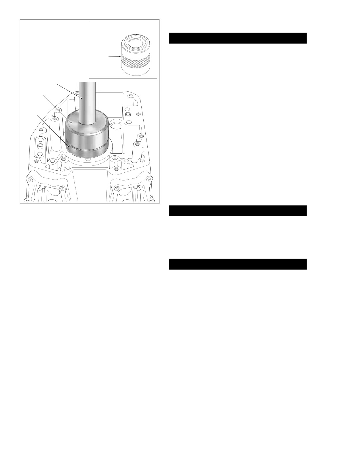
Figure 3-126. Install Crankshaft Bearing
1CAUTION
Never move or lift the crankcase by grasping the cylin-
der studs. The crankcase is too heavy to be carried in
5.
Start crankshaft bearing into bore with the lettered side
this manner and may be dropped. Dropping the crank-
up. Lubricate leading edge of bearing before placement.
case may result in parts damage and minor or moderate
6.
Slide pilot/driver through bearing into support tube.
injury.
7.
Center pilot/driver under ram of press. Apply pressure to
pilot/driver until resistance is felt and bearing bottoms in
1WARNING
support tube. See Figure 3-126.
Do NOT rotate left crankcase half in the engine stand so
8.
Remove pilot/driver and right crankcase half from sup-
the stator mount flange (sprocket shaft side) is facing up
port tube.
or the flywheel assembly will drop to the floor. Dropping
the flywheel assembly may result in parts damage and
minor or moderate injury.
1.
Holding flywheel assembly so that it does not drop out of
Piston Jets
left crankcase half, rotate cradle so that engine is upright
and crankshaft and sprocket shaft are horizontal.
Removal
2.
Carefully slide flywheel assembly out of left crankcase
1.
Remove two T20 TORX screws to free piston jet from
half.
crankcase.
3.
Remove left crankcase half from engine stand and move
2.
Remove O-ring from groove in mounting flange of jet.
to bench area. Remove thrust washer from outboard
Discard O-ring.
side of crankcase by pulling it past the oil seal. Set thrust
washer aside for inspection or reuse.
4.
Using a suitable drift, tap oil seal from bearing bore. Dis-
card oil seal.
3-102
2005 Touring: Engine
HOME
f2136x3x
1
f2132x3x
2
1
2
4
3
3
f2129x3x
f2129x3x
1.
Ram
1. Ram
3
2.
Pilot/Driver
3
2. Pilot/Driver
3.
Support Tube (“A” end up)
3. Support Tube (“A” end up)
4.
Sprocket Shaft Bearing
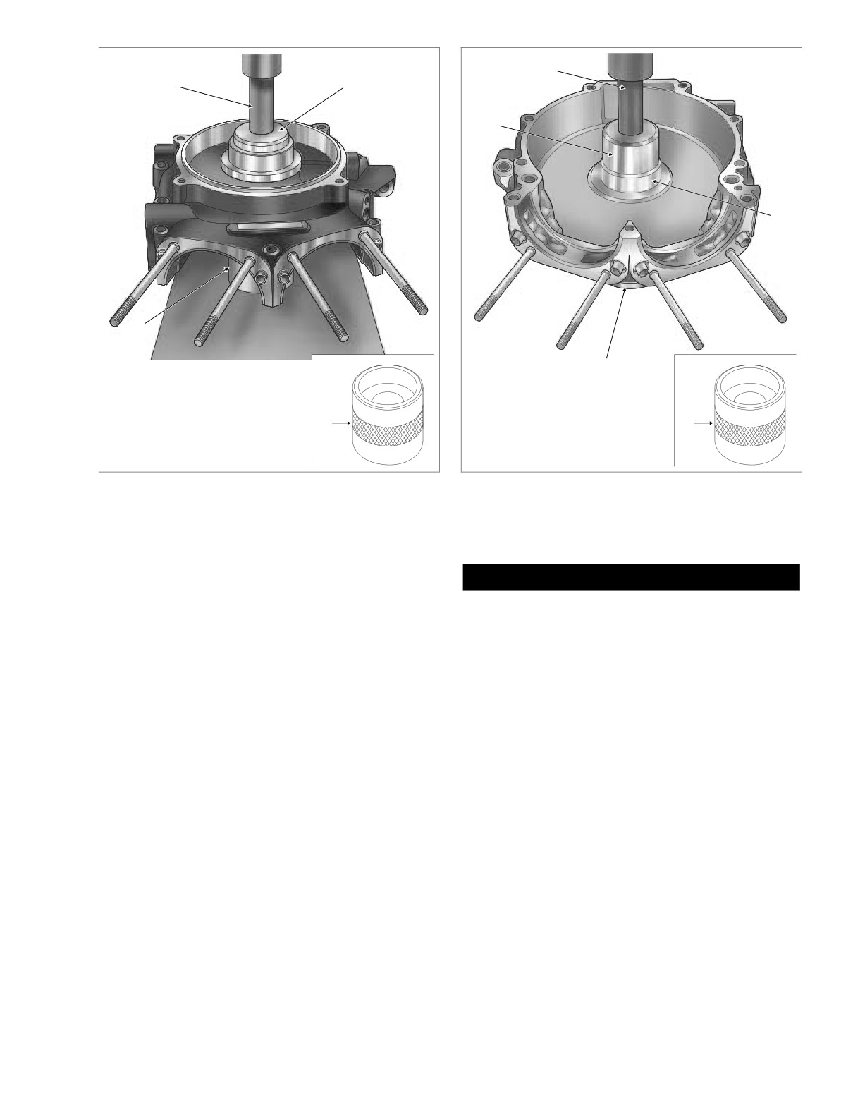
Figure 3-127. Remove Sprocket Shaft Bearing
Figure 3-128. Install Sprocket Shaft Bearing
5.
See Figure 3-124. Obtain CRANKSHAFT/SPROCKET
Installation
SHAFT BEARING REMOVER/INSTALLER SUPPORT
TUBE (HD-42720-5) and CRANKSHAFT/SPROCKET
1CAUTION
SHAFT BEARING REMOVER/INSTALLER PILOT/
DRIVER (B-45655).
Never move or lift the crankcase by grasping the cylin-
der studs. The crankcase is too heavy to be carried in
6.
Place left crankcase half on work bench with inboard
this manner and may be dropped. Dropping the crank-
side of facing upward.
case may result in parts damage and minor or moderate
7.
Using the tip of a flat blade screwdriver, carefully lift end
injury.
of lock ring out of groove in bearing bore. Working the
1.
See Figure 3-124. Obtain CRANKSHAFT/SPROCKET
screwdriver around the edge, lift the lock ring up and out
SHAFT BEARING REMOVER/INSTALLER SUPPORT
of the groove. Be careful not to damage the lip of the
TUBE (HD-42720-5) and CRANKSHAFT/SPROCKET
groove during removal.
SHAFT BEARING REMOVER/INSTALLER PILOT/
8.
Place support tube on hydraulic press table with the “A”
DRIVER (B-45655).
end up. The ends of the support tube are stamped “A”
2.
Place support tube on hydraulic press table with the “A”
and “B” to ensure proper orientation.
end up. The ends of the support tube are stamped “A”
9.
With the outboard side of the left crankcase half facing
and “B” to ensure proper orientation.
upward, position sprocket shaft bearing bore over sup-
3.
With inboard side of the left crankcase half facing
port tube. See Figure 3-127.
upward, position sprocket shaft bearing bore over sup-
port tube.
10.
Slide pilot/driver through bearing into support tube.
4.
See Figure 3-128. Obtain new sprocket shaft bearing
11.
Center pilot/driver under ram of press. Apply pressure to
and apply a thin film of clean engine oil to O.D.
pilot/driver until bearing is free.
5.
Start sprocket shaft bearing into bearing bore with the
12.
Remove left crankcase half, pilot/driver and bearing from
lettered side down. Lubricate leading edge of bearing
support tube. Discard bearing.
before placement.
2005 Touring: Engine
3-103
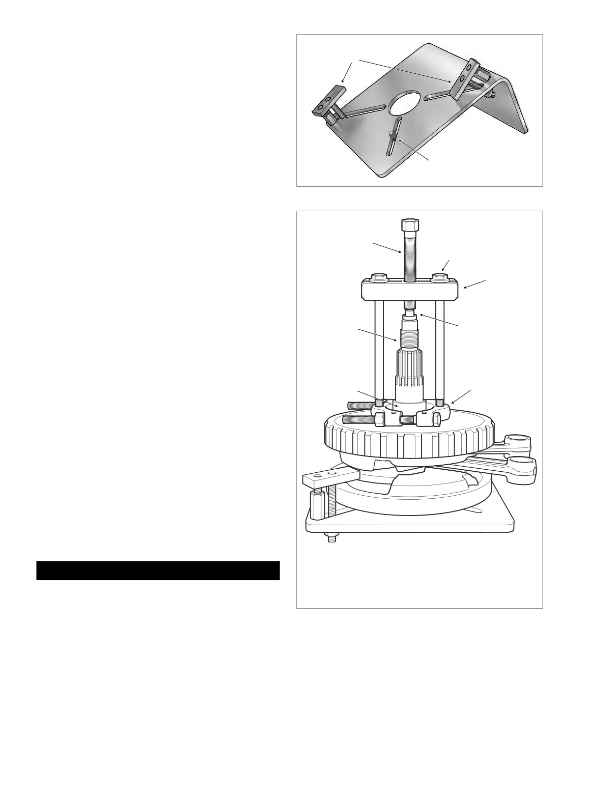
HOME
6.
Slide pilot/driver through bearing into support tube.
Hold-Down
7.
Center pilot/driver under ram of press. Apply pressure to
Clamp
pilot/driver until bearing lightly bottoms in the bore.
8.
Remove left crankcase half and pilot/driver from support
tube.
9.
Place left crankcase half on work bench with inboard
side of facing upward.
10. Obtain new lock ring and work into groove in bearing
bore. Be careful not to damage the lip of the groove dur-
ing installation. Verify that lock ring is fully seated in the
groove.
Locating Pin
NOTE
If lock ring will not fit into groove, bearing bore may not have
Figure 3-129. Flywheel Fixture (Part No. HD-44358)
been properly cleaned and/or bearing may not be fully
seated in the bore.
f2154x3x
1
Sprocket Shaft Bearing Inner Race
2
Removal
3
1.
If reusing flywheel, remove bearing inner race and thrust
washer as follows:
a. Obtain FLYWHEEL SUPPORT FIXTURE
(HD-
44358). See Figure 3-129. Install brass jaws or
shop towels around teeth of vise to prevent damage
7
4
to tool. Clamp tool in vise with the round hole top-
side.
b. Insert crankshaft end through hole resting flywheel
assembly on fixture. Slide knurled locating pin down
slot in tool to engage crank pin hole. Hand tighten
6
5
locating pin.
c. Slide hold-down clamp down slot to engage inboard
side of right flywheel half, and then hand tighten
knurled nut at bottom to secure. Repeat step to
secure hold-down clamp on opposite side of fly-
wheel.
NOTE
For proper clamping force, hold-down clamp must not be
tilted. Rotate hex on outboard stud until clamp is level.
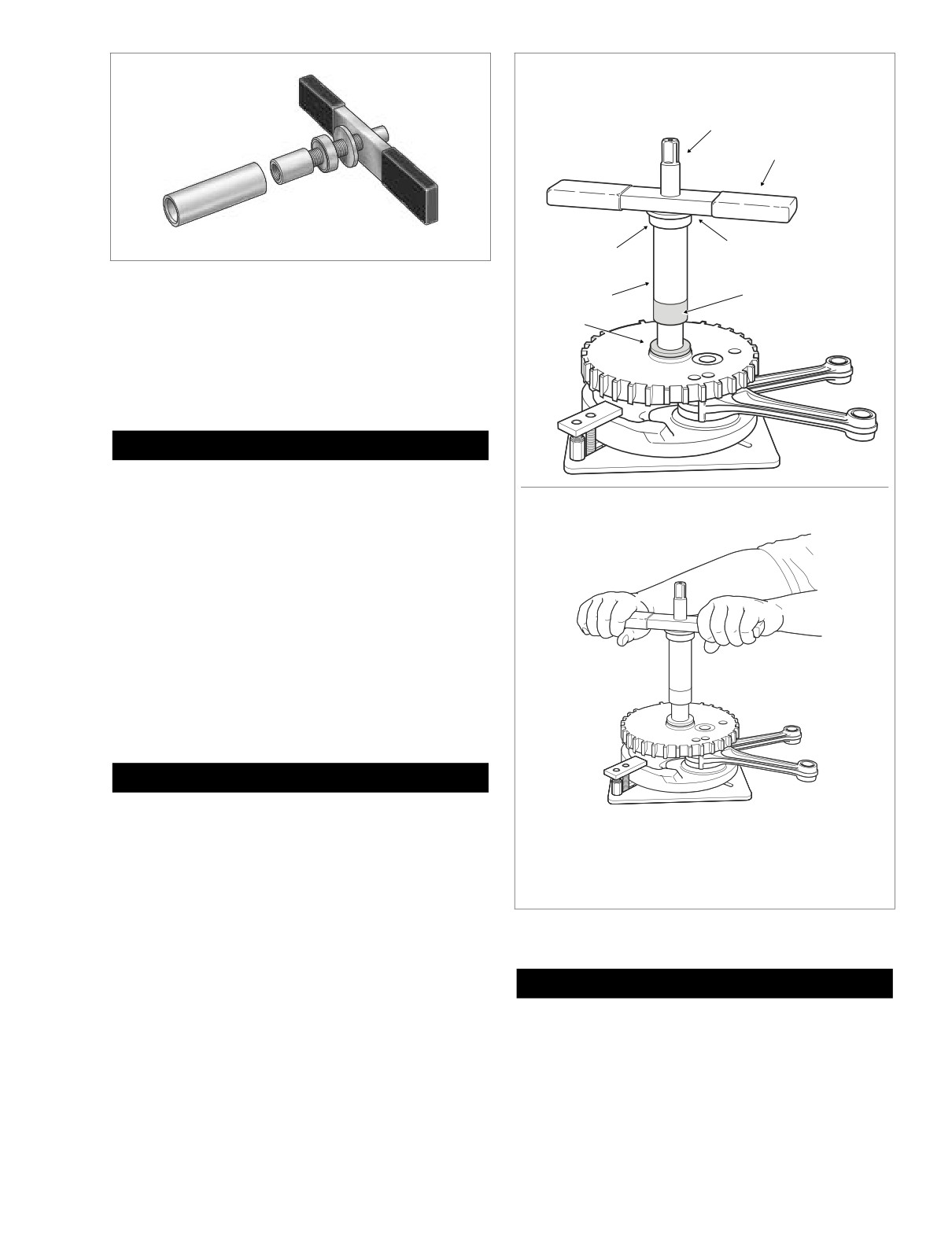
d. Position WEDGE ATTACHMENT (HD-95637-46A)
on inboard side of thrust washer and turn hex nuts
an equal number of turns to draw halves of wedge
together.
1.
Forcing Screw
4.
Hardened Plug
2.
3/8-16 Inch Bolt
5.
Wedge Attachment
CAUTION
with Flat Washer
6.
Bearing Inner Race
Install wedge attachment only so far as necessary to
3.
Bridge
7.
Sprocket Shaft
ensure positive contact with thrust washer. Installing
tool with more contact than absolutely necessary will
Figure 3-130. Remove Inner Race From Sprocket Shaft
result in damage to flywheel.
e. Obtain two 3/8-16 inch bolts 6-1/2 inches long (with
flat washers). Install flat washers on bolts. Obtain
f.
Slide one bolt into channel on each side of bridge
bridge, forcing screw and hardened plug from
so that flat washer is between bridge and bolt head.
MAINSHAFT BEARING INNER RACE PULLER/
Thread bolts into wedge attachment an equal num-
INSTALLER (HD-34902B).
ber of turns.
3-104
2005 Touring: Engine
HOME
f2265x3x
1. Install Thrust Washer and Bearing Inner Race On
Sprocket Shaft. Assemble Tool.
1
2
3
4
Figure 3-131. Sprocket Shaft Timken Bearing
Cone Installer (Part No. HD-97225-55B)
6
5
7
g. Sparingly apply graphite lubricant to threads of forc-
ing screw to prolong service life and ensure smooth
operation. Start forcing screw into center hole of
bridge.
CAUTION
f2152x3x
Failure to use hardened plug may result in damage to
forcing screw and/or sprocket shaft.
2. Press Bearing Inner Race Onto Sprocket Shaft.
h. Place cupped side of hardened plug against end of
sprocket shaft. Thread forcing screw into bridge until
f2153x3x
the steel ball at the end of the screw makes firm
contact with hardened plug.
i.
Using the Robinair Heat Gun (HD-25070), uniformly
heat the bearing inner race for about 30 seconds
using a circular motion.
NOTE
To faciliate removal without heat, apply a light penetrating oil
to shaft and leading edge of bearing inner race.
1WARNING
Never use both heat and penetrating oil. Use only one or
the other. Excessive heat can cause the penetrating oil
1. Pilot Shaft
5.
Sleeve
to ignite resulting in flames or fire. Inadequate safety
2. Handle
6.
Inner Race
precautions can result in death or serious injury.
3. Flat Washer
7.
Thrust Washer
4. Nice Bearing
j.
Turn forcing screw until thrust washer and bearing
inner race move approximately 1/8 inch (3.2 mm).
Figure 3-132. Press Inner Race Onto Sprocket Shaft
k. Turn hex nuts an equal number of turns to separate
halves of WEDGE ATTACHMENT.
CAUTION
l.
After bottoming thrust washer on shaft, reposition
WEDGE ATTACHMENT
(HD-95637-46A) on
Install wedge attachment only so far as necessary to
inboard side of bearing inner race. Turn hex nuts an
ensure positive contact with bearing inner race. Install-
equal number of turns to draw halves of wedge
ing tool with more contact than absolutely necessary
together.
will result in damage to flywheel.
2005 Touring: Engine
3-105
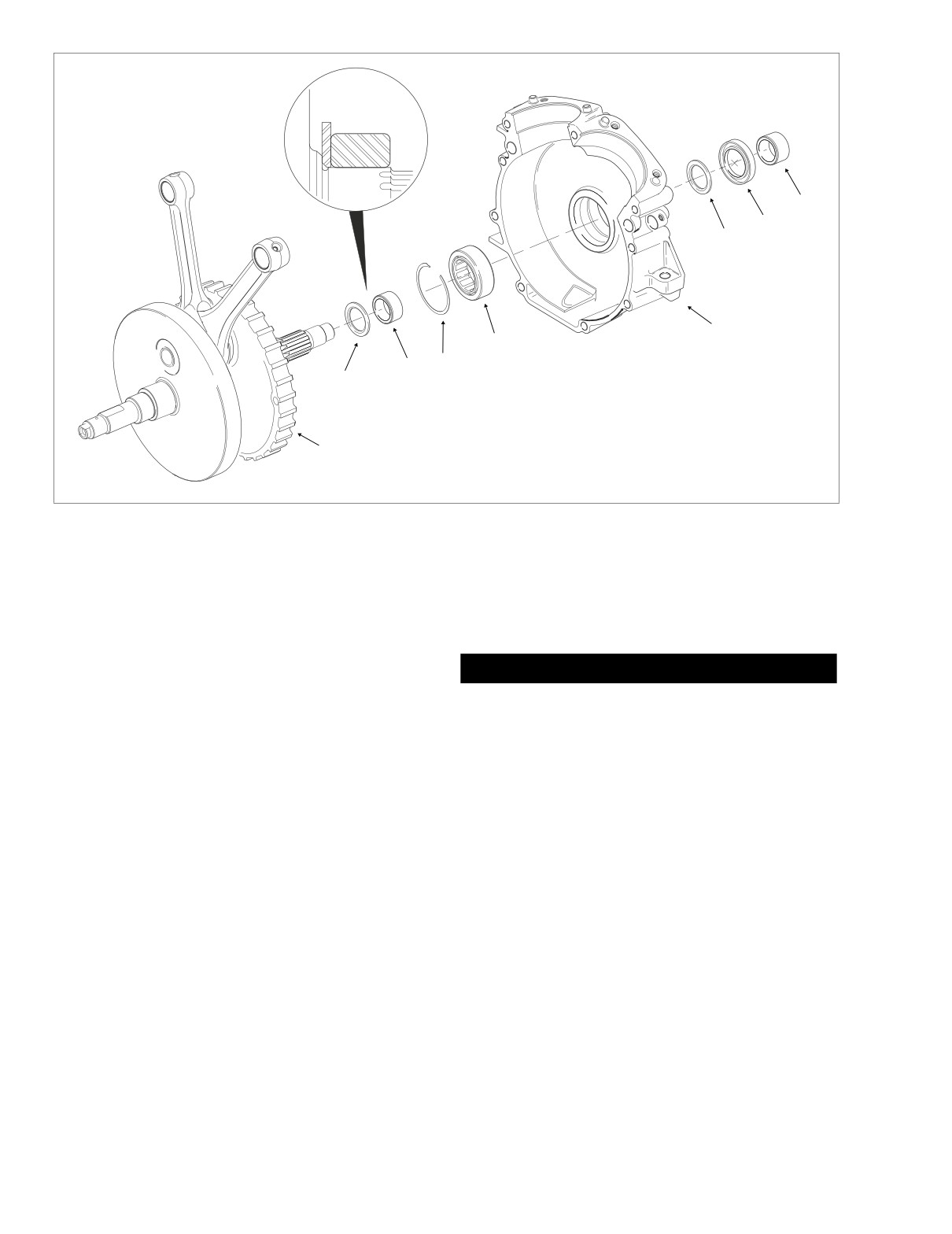
HOME
f2266x3x
9
8
7
6
5
3
4
2
5.
Bearing
1. Flywheel Assembly
6.
Left Crankcase Half
2. Thrust Washer
7.
Thrust Washer
3. Inner Race
8.
Oil Seal
1
4. Lock Ring
9.
Spacer
Figure 3-133. Sprocket Shaft Bearing Assembly
m. Verify that the tool assembly is square, so that the
NOTE
bearing inner race is not cocked during removal.
To faciliate installation without heat, apply a light penetrating
See Figure 3-130.
oil to shaft and leading edge of bearing inner race.
n. Using the Robinair Heat Gun (HD-25070), uniformly
heat the bearing inner race for about 30 seconds
using a circular motion.
1WARNING
Never use both heat and penetrating oil. Use only one or
NOTE
the other. Excessive heat can cause the penetrating oil
To faciliate removal without heat, apply a light penetrating oil
to ignite resulting in flames or fire. Inadequate safety
to shaft and leading edge of bearing inner race.
precautions can result in death or serious injury.
o. Turn forcing screw until bearing inner race is pulled
4.
Obtain the SPROCKET SHAFT TIMKEN BEARING
free of sprocket shaft.
CONE INSTALLER (HD-97225-55B). See Figure 3-131.
p. Remove thrust washer from sprocket shaft.
Assemble tool as described below.
a. Thread pilot onto sprocket shaft until contact is
2.
Discard thrust washer and bearing inner race.
made with shoulder.
b. Sparingly apply graphite lubricant to threads of pilot
Installation
shaft to prolong service life and ensure smooth
1.
Place new thrust washer over sprocket shaft with the ink
operation.
stamp facing outside
(and the chamfer on the ID
c. Slide sleeve over pilot until it contacts bearing inner
inboard).
race.
2.
Place new bearing inner race on bench top. Using the
Robinair Heat Gun (HD-25070), uniformly heat bearing
d. Slide Nice bearing and large flat washer over pilot
inner race for about 60 seconds using a circular motion.
until contact is made with sleeve.
3.
Wearing suitable gloves to protect hands from burns,
e. Thread handle onto pilot shaft. See upper frame of
place heated bearing inner race over sprocket shaft.
Figure 3-132.
3-106
2005 Touring: Engine
HOME
5. Rotate handle of tool in a clockwise direction until bear-
5.
Check ring dowels for looseness, wear or damage.
ing inner race bottoms against thrust washer. See lower
Replace as necessary.
frame of Figure 3-132.
6.
Use a file to carefully remove any nicks or burrs from
6. Remove handle, flat washer, Nice bearing, sleeve and
machined surfaces.
pilot from sprocket shaft.
7.
Clean out tapped holes and clean up damaged threads.
8.
Check the top of the crankcase for flatness with a
Cylinder Studs
straightedge and feeler gauge. Replace if warped.
Removal
1. Thread a 3/8”-16 nut onto cylinder stud.
Installation
2. Thread a second nut onto stud until it contacts the first.
1.
See Section 3.10 BOTTOM END OVERHAUL, ASSEM-
3. Placing wrench on first nut installed, remove stud from
BLY, steps 1-29.
cylinder deck.
2.
See Section 3.9 TOP END OVERHAUL, ASSEMBLY,
Installation
steps 1-39.
1. Hand start stud in cylinder deck with the collar side
down.
2. Install steel ball bearing into unused cylinder head bolt.
Position head bolt on end of stud.
3. Using an air gun, tighten stud until collar almost contacts
cylinder deck.
4. Leaving cylinder head bolt installed, hand tighten stud to
10-20 ft-lbs (14-27 Nm).
Pipe Plug and Oil Fittings
Removal
1. Turn hex on oil fittings in a counterclockwise direction
until free.
2. Turn pipe plug in a counterclockwise direction until free.
Installation
1. Apply Loctite Pipe Sealant with Teflon 565 to threads.
2. Turn hex on oil fittings in a clockwise direction until snug.
Tighten fittings to 120-168 in-lbs (13.6-18.9 Nm).
3. Install pipe plug. Tighten pipe plug to 120-168 in-lbs
(13.6-18.9 Nm).
Cleaning and Inspection
1. Scrape old gasket material from the crankcase flanges.
Old gasket material left on mating surfaces will cause
leaks.
2. Clean all parts in a non-volatile cleaning solution or sol-
vent.
3. Thoroughly dry all parts with low pressure compressed
air.
4. Verify that all oil holes and passageways are clean and
open.
2005 Touring: Engine
3-107
HOME
FLYWHEEL/CONNECTING ROD
ASSEMBLY
Removal
1.
See Section 3.9 TOP END OVERHAUL, DISASSEM-
BLY, steps 1-29.
2.
See Section 3.10 BOTTOM END OVERHAUL, DISAS-
SEMBLY, steps 1-18.
3.
See Section
3.11 SUBASSEMBLY SERVICE AND
REPAIR, CRANKCASE, LEFT CRANKCASE HALF,
SPROCKET SHAFT BEARING, REMOVAL.
f1690x3x
Inspection
1.
Replace the flywheel/connecting rod assembly if any of
Figure 3-135. Check Connecting Rod Side Play
the following conditions are noted:
● The crankshaft/sprocket shaft bearing inner races
CAUTION
are brinelled, burnt, scored, blued or damaged.
Do not attempt to straighten connecting rods. Straight-
ening rods will damage both the upper bushing and
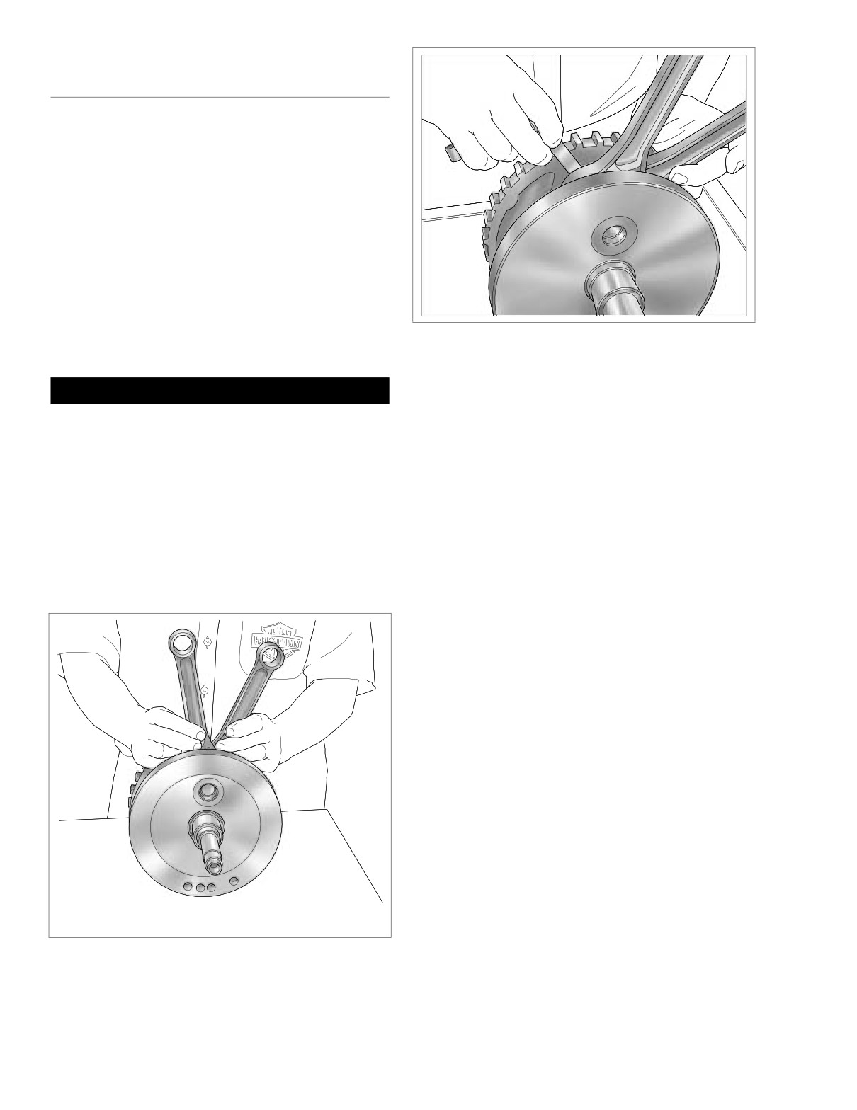
2. Orient the assembly as shown in Figure 3-134. Holding
lower bearing.
the shank of each rod just above the bearing bore, pull
up and down on the connecting rods. Any discernable
● Connecting rods are bent or twisted.
up and down movement indicates excessive lower
● Connecting rods do not fall under their own weight
bearing clearance. Replace the flywheel/connecting rod
or are in a bind.
assembly.
NOTE
3. Insert a feeler gauge between the thrust washer and the
Bluing on connecting rods is from induction hardening and is
outboard side of the connecting rod. See Figure 3-135.
considered a normal condition.
Replace the assembly if rod side play exceeds 0.020
inch (0.51 mm).
NOTE
If the flywheel, connecting rods or right side bearing inner
race need to be replaced, then replace the entire flywheel
assembly.
Installation
1.
See Section
3.11 SUBASSEMBLY SERVICE AND
REPAIR, CRANKCASE, LEFT CRANKCASE HALF,
SPROCKET SHAFT BEARING, INSTALLATION.
2.
See Section 3.10 BOTTOM END OVERHAUL, ASSEM-
BLY, steps 1-29.
3.
See Section 3.9 TOP END OVERHAUL, ASSEMBLY,
steps 1-39.
f1689x3x
Figure 3-134. Check Connecting Rod Bearing Clearance
3-108
2005 Touring: Engine
Table Of Contents
FUEL SYSTEM
4
SUBJECT
PAGE NO.
4.1 Specifications
4-1
4.2 Fuel System Troubleshooting
4-2
4.3 Enrichener
4-5
4.4 Carburetor
4-9
4.5 Air Cleaner
4-16
4.6 Vacuum Operated Fuel Valve
4-18
4.7 Fuel Tank
4-21
4.8 Evaporative Emissions Control System
4-27
HOME
SPECIFICATIONS
4.1
CVH CARBURETOR JET SIZES
TORQUE VALUES
Main Fuel
Slow Fuel
Model
Item
ft/in-lbs
Nm
Jet No.
Jet No.
Enrichener cable
49 state
190
45
20-35 in-lbs
2.3-4.0 Nm
mounting bracket hex nut
HDI
195
45
Cylinder head breather
120-144 in-lbs
13.6-16.3 Nm
bolts
California
185
45
Air cleaner cover bracket
20-40 in-lbs
2.3-4.5 Nm
screws
Air cleaner cover screw
36-60 in-lbs
4.1-6.8 Nm
FUEL TANK CAPACITY
Fuel valve hex jam nut
15-20 ft-lbs
20-27 Nm
Fuel tank adapter
22-26 ft-lbs
30-35 Nm
Capacity
English
Metric
Fuel tank rear mounting
15-20 ft-lbs
20-27 Nm
bolt
Total
5.0 Gallons
18.9 liters
Fuel tank front mounting
Reserve
0.9 Gallons
3.4 liters
15-20 ft-lbs
20-27 Nm
bolts
Battery hold-down clamp
15-20 ft-lbs
20-27 Nm
bolt
Console mounting bolt
50-90 in-lbs
5.7-10.2 Nm
acorn nut
2005 Touring: Fuel
4-1

HOME
FUEL SYSTEM TROUBLESHOOTING (CARBURETED)
4.2
\
CARBURETOR TROUBLESHOOTING
OVERFLOW
Check for:
Remedy:
1.
Restricted fuel tank vent system.
1.
Correct restricted hose. Replace vapor valve.
2.
Loose float bowl screws.
2.
Tighten screws.
3.
Damaged float bowl O-ring.
3.
Replace O-ring.
4.
Improper fuel level in float bowl.
4.
Adjust float tab for correct fuel level.
5.
Damaged or leaking float assembly.
5.
Replace float assembly.
6.
Particle contamination in fuel inlet fitting cavity.
6.
Clean and clear cavity and fuel supply tract.
7.
Worn or dirty inlet valve or seat.
7.
Clean or replace valve and clean seat.
POOR IDLING
Check for:
Remedy:
1.
Idle speed improperly adjusted.
1.
Adjust operating idle speed.
2.
Inlet system air leak (faster idling).
2.
Correct as required.
3.
Loose low speed jet.
3.
Tighten jet.
4.
Contaminated or plugged low speed system.
4.
Clean contaminants and clear passages.
5.
Enrichener valve not seated or leaking.
5.
Adjust, clean or replace.
6.
Leaking accelerator pump.
6.
Repair.
POOR FUEL ECONOMY
Check for:
Remedy:
1.
High speed riding style.
1.
Modify riding habits.
2.
Excessive use of enrichener system.
2.
Limit system use.
3.
Fuel level too high.
3.
Adjust float level.
4.
Restricted fuel tank vent system.
4.
Correct restricted hose. Replace vapor valve.
5.
Dirty air cleaner element.
5.
Clean or replace as required.
6.
Excessive accelerator pump output.
6.
Check and clean accelerator pump bypass orifice.
7.
Plugged or restricted bowl vent.
7.
Clean and clear passages.
8.
Vacuum piston assembly malfunction.
8.
See Vacuum Piston Troubleshooting.
9.
Loose jets.
9.
Tighten jets.
10. Worn or damaged needle or needle jet.
10. Replace needle or needle jet.
11. Plugged air jets or passages.
11. Clean and clear passages.
12. Enrichener valve not seated or leaking.
12. Adjust, clean or replace.
13. Idle speed improperly adjusted.
13. Adjust operating idle speed.
POOR ACCELERATION
Check for:
Remedy:
1. Throttle cables misadjusted.
1.
Adjust throttle cables.
2. Inlet system air leak.
2.
Correct as required.
3. Restricted fuel tank vent system.
3.
Correct restricted hose. Replace vapor valve.
4. Restricted fuel supply passages.
4.
Correct and clear restriction.
5. Plugged bowl vent or overflow.
5.
Clean and clear passages.
6. Enrichener valve not seated or leaking.
6.
Adjust, clean or replace.
7. Worn or damaged needle or needle jet.
7.
Replace assembly.
8. Vacuum piston malfunction.
8.
See Vacuum Piston Troubleshooting.
9. Plugged jets or passages.
9.
Clean and clear as required.
10. Fuel level (float chamber) too low.
10. Adjust float level.
11. Accelerator pump leaking or no output.
11. Repair as necessary.
4-2
2005 Touring: Fuel

HOME
HARD STARTING
Check for:
Remedy:
1. Enrichener system plugged, not properly functioning
1. Clean, adjust, or replace; or read Owner’s Manual.
or improperly operated.
2. Correct as required.
2. Inlet system air leak.
3. Check fuel supply and/or passages. Verify that vacuum
3. Restricted fuel supply.
operated fuel valve is functional.
4. Fuel overflow.
4. See Overflow Troubleshooting.
5. Plugged slow jet or passages.
5. Clean and clear jet or passages.
POOR PERFORMANCE ON ROAD
Check for:
Remedy:
1. Inlet system air leak.
1. Correct as required.
2. Restricted fuel tank vent system.
2. Correct restricted hose. Replace vapor valve.
3. Dirty or damaged air cleaner element.
3. Clean or replace.
4. Accelerator pump inoperative.
4. Repair as required.
5. Plugged bowl vent or overflow.
5. Clean and clear passages.
6. Vacuum piston assembly malfunction.
6. See Vacuum Piston Troubleshooting.
7. Loose or plugged fuel and air jets or passages.
7. Clean, clear and correct as required.
8. Worn or damaged needle or needle jet.
8. Replace assembly.
9. Restricted fuel supply tract.
9. Correct and clear restriction.
10. Enrichener valve not seated or leaking.
10. Adjust, clean or replace.
11. Idle speed improperly adjusted.
11. Adjust operating idle speed.
POOR HIGH SPEED PERFORMANCE
Check for:
Remedy:
1.
Inlet system air leak.
1.
Clean or replace.
2.
Restricted fuel tank vent system.
2.
Correct restricted hose. Replace vapor valve.
3.
Dirty or damaged air cleaner element.
3.
Clean or replace.
4.
Accelerator pump inoperative.
4.
Repair as required.
5.
Plugged bowl, vent or overflow.
5.
Clean and clear passages.
6.
Vacuum piston assembly malfunction.
6.
See Vacuum Piston Troubleshooting.
7.
Restricted fuel supply tract.
7.
Correct and clean restriction.
8.
Loose or plugged main jets or passages.
8.
Tighten, clean, clear as required.
9.
Improper fuel level.
9.
Adjust float level.
10. Worn or damaged needle or needle jet.
10. Replace assembly.
11. Enrichener valve not seated or leaking.
11. Adjust, clean or replace.
2005 Touring: Fuel
4-3

HOME
VACUUM PISTON ASSEMBLY TROUBLESHOOTING
PISTON DOES NOT RAISE PROPERLY
Check for:
Remedy:
1. Diaphragm cap loose, damaged or leaking.
1.
Tighten or replace cap.
2. Diaphragm pinched at lip groove.
2.
Reposition diaphragm lip.
3. Piston atmosphere vent blocked.
3.
Clear vent.
4. Piston vacuum passage plugged.
4.
Clean and clear passage.
5. Torn diaphragm.
5.
Replace piston diaphragm assembly.
6. Piston binding.
6.
Clean piston slides and body or replace piston.
7. Spring binding.
7.
Correct or replace spring.
8. Enrichener valve open, not seated or leaking.
8.
Adjust, clean or replace.
PISTON DOES NOT CLOSE PROPERLY
Check for:
Remedy:
1. Piston diaphragm ring dirty or damaged.
1.
Clean or replace piston.
2. Piston binding.
2.
Clean piston slides and body or replace piston.
3. Spring damaged.
3.
Replace spring.
4-4
2005 Touring: Fuel
HOME
ENRICHENER (CARBURETED)
4.3
GENERAL
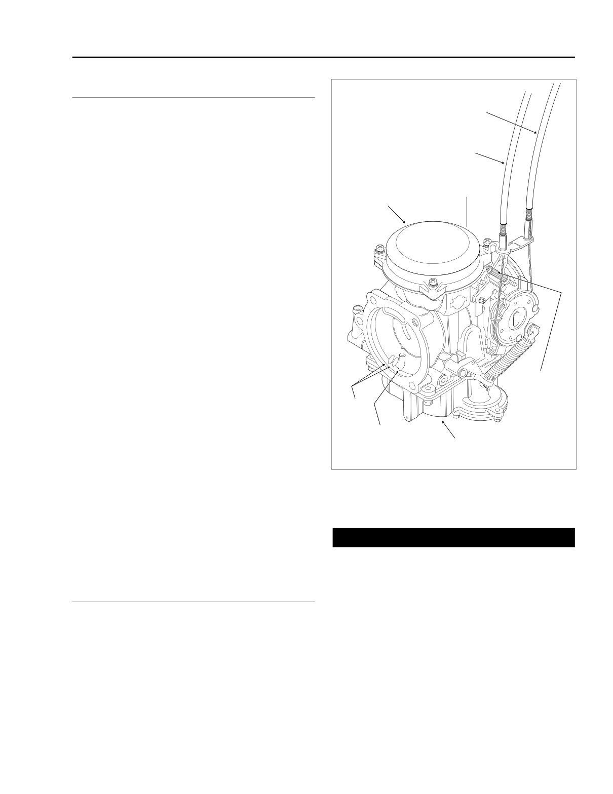
f1381b2x
Idle Control
Cable
The carburetor is a constant velocity, gravity fed type with a
float operated inlet valve, a variable venturi, a throttle stop
screw for idle speed adjustment and a fuel enrichment sys-
Throttle Control
tem for starting. See Figure 4-1.
Cable
The fuel enrichment circuit will cause engine idle speed to
increase to approximately 2000 rpm with enrichener knob
Vacuum Fitting
pulled out fully and engine running at normal operating tem-
Vacuum Piston
(At Back)
perature. With enrichener knob pulled out partially and
Chamber
engine running at normal operating temperature, engine idle
speed will also increase above normal idle speed. The
increase in idle speed is intended to alert the rider that
engine is warmed up, and that enrichener knob should be
pushed in all the way. Continued use of enrichener after
engine is warmed up may cause fouled spark plugs.
Idle and transfer ports provide a balanced fuel mixture during
the transition period from stop to mid-range. A vacuum piston
controls venturi opening.
The carburetor is specifically designed to control exhaust
emissions. All jets are fixed. The idle mixture has been pre-
set at the factory.
The idle mixture screw is recessed in the carburetor casting.
The opening is sealed with a plug because it is intended that
Idle Speed
the idle mixture be non-adjustable.
Set Screw
NOTE
Air
Jets
Adjusting mixture setting by procedures other than specified
in this section may be in violation of Federal or State regula-
Accelerator
tions.
Pump Nozzle
Float Chamber
This system partially compensates for changes in the mixture
that are normally caused by changes in altitude. Because
Figure 4-1. CVH Carburetor
atmospheric pressure decreases as altitude increases, the
pressure difference in the upper and lower chambers is
reduced, which provides less fuel to the engine.
The carburetor is equipped with an accelerator pump. The
accelerator pump system uses sudden throttle openings
CAUTION
(rapid accelerations) to quickly inject fuel into carburetor ven-
turi to provide extra fuel for smooth acceleration.
Never accelerate the engine above 2500 RPM immedi-
ately after a cold start. Allow the engine to run slowly for
15-30 seconds. This will allow the engine to warm up and
OPERATION
let oil reach all surfaces needing lubrication. Extended
idling with enrichener in the full out position for a period
longer than 30 seconds is not recommended.
Enrichener
NOTE
The enrichener knob, located under the left side of the fuel
● H-D CV carburetors have an enrichener circuit that will
tank, controls opening and closing of the enrichener circuit in
cause the engine to idle at approximately 2000 rpm with
the carburetor. The enrichener knob can be adjusted to any
the engine at normal operating temperature and the
position, from full-in to full-out.
enrichener knob pulled fully out.
2005 Touring: Fuel
4-5