Harley Davidson 2013 Sportster Models. Service Manual - page 22
 

  Главная      Harley Davidson     Harley Davidson 2013 Sportster Models. Service Manual


Search            copyright infringement  


Content      ..     20      21      22      23     ..


Harley Davidson 2013 Sportster Models. Service Manual - page 22


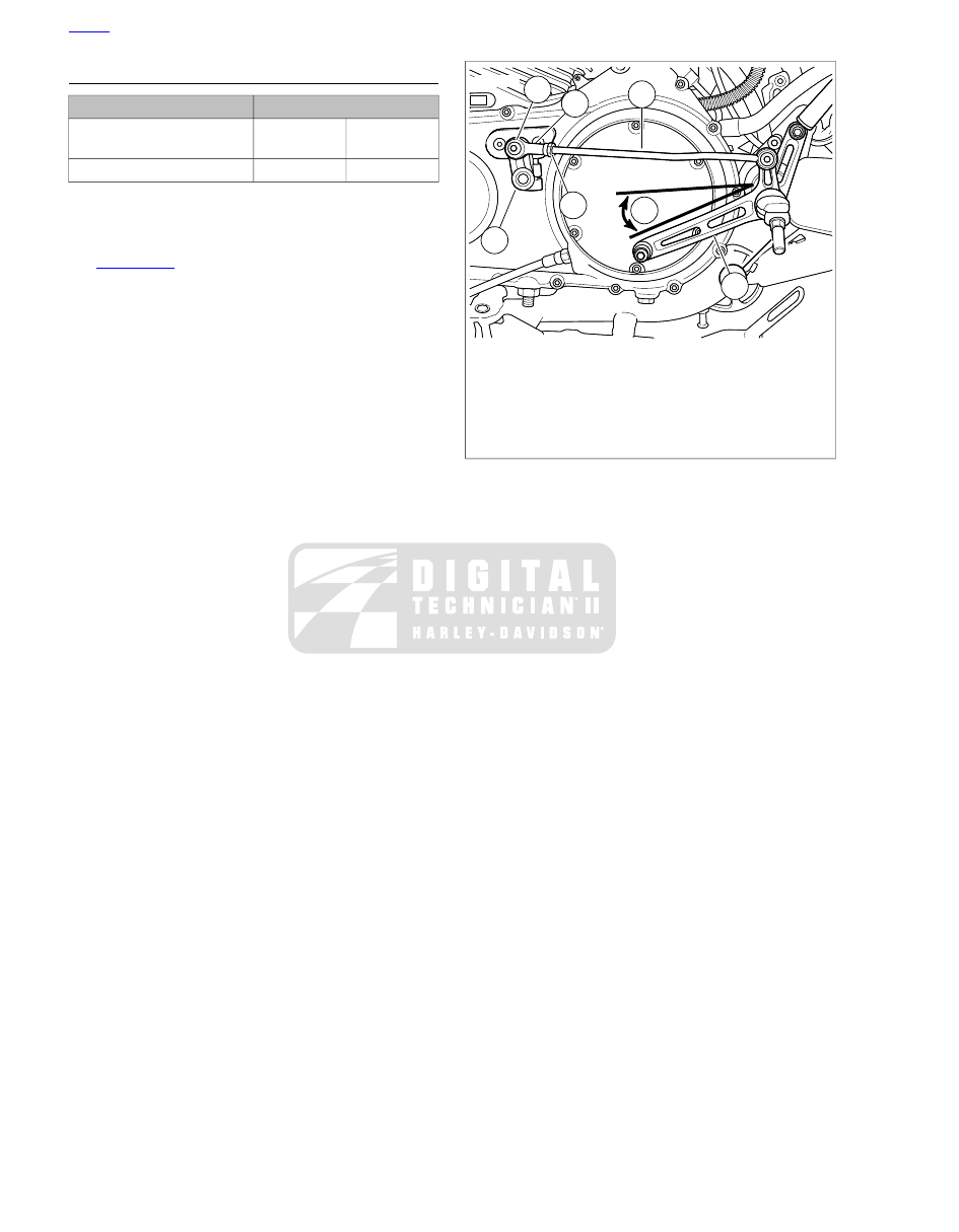
ADJUSTING SHIFT LEVER

TORQUE VALUE

FASTENER

13.6-20.4 Nm

120-180

in-lbs

Shift rod screw

9.5-14.9 Nm

84-132

in-lbs

Shift rod jamnuts

The foot shift linkage is set at the factory and normally should
need no adjustment. However, the shift linkage can be adjusted
for rider preference.

See

Figure 2-237

. Adjust shifter rod assembly (4) length until

shifter lever (5) is at approximately 20 degrees from horizontal
as shown in the figure.

1.

Loosen jamnut (3) on front end of shifter rod.

2.

Remove screw (1) securing ball joint (2) to shifter arm (6).

3.

Turn ball joint in one direction or the other to adjust rod
length as necessary. Temporarily attach ball joint to shifter
arm and check angle.

4.

When angle of shift lever assembly is at 20 degrees, install
screw (1). Tighten to 120-180

in-lbs

(13.6-20.4 Nm).

5.

Holding ball joint with a wrench on the flats, tighten the
jamnuts to 84-132

in-lbs

(9.5-14.9 Nm).

2

4

7

2

1

6

3

5

sm06933a

1. Screw
2. Ball joint
3. Jamnut
4. Shifter rod
5. Shifter lever assembly
6. Shifter arm
7. 20 degrees

Figure 2-237. Adjusting Shift Pedal: XR 1200X

HOME

2-168 2013 Sportster Service: Chassis

2.43

PASSENGER FOOTRESTS

XL MODELS

TORQUE VALUE

FASTENER

61-68 Nm

45-50 ft-lbs

Passenger footrest support
bracket fastener: XL Models

Removal

1.

See

Figure 2-238

. Remove retaining ring (1), clevis pin

(2), footrest (3) and spring washer (4). Discard retaining
ring.

2.

Remove two screws (5) and footrest support bracket (6)
from frame (7).

Installation

NOTE

See

Figure 2-238

. Position clamp (8) between the left footrest

support bracket (6) and the lower support bracket hole in the
frame.

1.

See

Figure 2-238

Attach footrest support bracket (6) to

frame (7) with two fasteners (5). Tighten to 45-50 ft-lbs
(61-68 Nm).

2.

Install footrest (3) on footrest support bracket with spring
washer (4). Make sure spring washer is positioned inside
support bracket mounting boss with the square edge
toward the inside.

3.

Align holes and push clevis pin (2) from top down through
hole in support bracket. Secure with

new

retaining ring

(1).

7

8

6

5

4

2

3

1

sm02209b

1. Retaining ring
2. Clevis pin
3. Footrest
4. Spring washer
5. Fastener (2)
6. Footrest support bracket
7. Frame
8. Clamp (left side only)

Figure 2-238. Passenger Footrest Assembly (optional on

some models)

HOME

2013 Sportster Service: Chassis 2-169

XR 1200X

TORQUE VALUE

FASTENER

61-68 Nm

45-50 ft-lbs

Passenger footrest support
bracket fastener: XR 1200X

20.4-25.8 Nm

15-19 ft-lbs

Muffler bracket to footrest
bracket screw: XR 1200X

Removal

1.

See

Figure 2-239

. Remove retaining ring (4), clevis pin

(2), footrest and spring washer (3). Discard retaining ring.

2.

On right side of vehicle, remove screw securing muffler
bracket to footrest support bracket.

3.

Remove two fasteners (6), washers (5) and footrest sup-
port (7, 8) from frame.

Installation

1.

See

Figure 2-239

. Attach left and right footrest support (7,

8) to frame with two fasteners (6) and washers (5). Tighten
to 45-50 ft-lbs (61-68 Nm).

2.

Attach muffler bracket to footrest support bracket with
screw. Tighten to 15-19 ft-lbs (20.4-25.8 Nm).

3.

Install footrests on footrest support with spring washer (3).
Make sure spring washer is positioned inside support
bracket mounting boss with the square edge toward the
inside.

4.

Align holes in footrest and support bracket and push clevis
pin (2) from top down through hole in support bracket.
Secure with

new

retaining ring (4).

9

1

5

7

3

3

4

2

8

2

4

1

6

6

5

10

sm06945

1. Plug
2. Clevis pin
3. Spring washer
4. Retaining ring
5. Washer
6. Fastener
7. RH support
8. LH support
9. Heel rest
10. Fastener

Figure 2-239. Left and Right Passenger Footrests

HOME

2-170 2013 Sportster Service: Chassis

2.44

FORK LOCK

REMOVAL

To prevent spray of fuel, purge system of high-pressure
fuel before supply line is disconnected. Gasoline is
extremely flammable and highly explosive, which could
result in death or serious injury. (00275a)

1.

Purge the fuel supply hose of high pressure gasoline.
Disconnect fuel supply hose from fuel pump module. See

4.4 FUEL TANK: XL MODELS

or

4.5 FUEL TANK: XR

1200X

.

To prevent accidental vehicle start-up, which could cause
death or serious injury, remove main fuse before pro-
ceeding. (00251b)

2.

Remove main fuse.

3.

Remove fuel tank. See

4.4 FUEL TANK: XL MODELS

or

4.5 FUEL TANK: XR 1200X

.

4.

Turn front forks full left lock.

5.

See

Figure 2-240

. See

Figure 2-241

Using a 5/64 drill bit,

carefully drill a hole in the center of the lock pin.

NOTE

Take time to carefully orient drill bit to center of lock pin. If drill
bit slides off-center, removal of lock pin will be difficult.

6.

See

Figure 2-242

To remove lock pin, insert a screw

extractor into the drilled hole. Hold body of screw extractor
with a pliers or tap handle and using a small hammer
gently "tap" on the pliers or tap handle to remove lock pin.

7.

Remove lock assembly.

sm01230

Figure 2-240. Fork Lock Pin

sm01231

Figure 2-241. Drilling Lock Pin

sm01232

Figure 2-242. Removing Lock Pin

HOME

2013 Sportster Service: Chassis 2-171

INSTALLATION

1.

Insert

new

lock assembly in frame lock housing.

2.

Align lock pin hole in

new

lock assembly with hole in the

frame lock housing.

3.

Drive

new

lock pin in position (flush with frame lock

housing).

4.

Install fuel tank. See

4.4 FUEL TANK: XL MODELS

or

4.5 FUEL TANK: XR 1200X

.

5.

Verify proper operation of fork lock.

a.

Turn front forks fully to the left.

b.

Insert key into fork lock. Turn key 90 degrees clock-
wise.

c.

Verify that front forks are locked and cannot be turned.

d.

Turn key 90 degrees counterclockwise and remove
from fork lock.

e.

Verify that front forks are now free to fully turn right
and left.

6.

Install main fuse.

HOME

2-172 2013 Sportster Service: Chassis

2.45

MEDALLIONS, SERIALIZED BADGES AND TANK
EMBLEMS

REMOVAL

1.

Mark location of emblem with masking tape.

NOTE

Wear protective gloves.

2.

Saw behind emblem with mono-filament fishing line or
waxed dental floss to remove emblem.

3.

Use 3M GENERAL PURPOSE ADHESIVE REMOVER to
remove remaining foam backing tape and adhesive from
mounting surface.

NOTE

For maximum bond, the surface must be clean and dry.

4.

Clean with a mixture of 50 percent isopropyl alcohol and
50 percent distilled water.

NOTE

Apply medallion within minutes of cleaning.

5.

Allow surface to dry.

INSTALLATION

NOTES

Apply in ambient temperatures between 70-100 °F (21-38
°C).

Do not remove protective film from adhesive until ready
to apply.

Do not bend emblem to fit contour of mounting surface.

1.

Test fit medallion in intended location

a.

Check medallion against curve of mounting surface.

b.

Match left and right sides of fuel tank.

NOTES

Protect adhesive from grease, oil, dust, dirt and finger
prints.

Once applied, do not shift the medallion.

The adhesive bonds in 72 hours at room temperature.

2.

Remove protective film from back of medallion.

3.

Apply even pressure across the entire surface with palms
and fingers of both hands. Hold in place for 15 seconds.

4.

Wait 20 minutes before touching medallion.

5.

Wait 24 hours before washing.

HOME

2013 Sportster Service: Chassis 2-173

TABLE OF CONTENTS

SUBJECT

............................................................................................................................

PAGE NO.

3.1 FASTENER TORQUE VALUES.................................................................................................3-1
3.2 SPECIFICATIONS.....................................................................................................................3-5
3.3 OIL PRESSURE......................................................................................................................3-10
3.4 CRANKCASE BREATHING SYSTEM.....................................................................................3-13
3.5 TROUBLESHOOTING.............................................................................................................3-14
3.6 ENGINE LUBRICATION SYSTEM..........................................................................................3-16
3.7 HOW TO USE THIS SECTION................................................................................................3-25
3.8 TOP END SERVICE................................................................................................................3-26
3.9 BOTTOM END SERVICE........................................................................................................3-28
3.10 REMOVING ENGINE FROM CHASSIS................................................................................3-30
3.11 INSTALLING ENGINE IN CHASSIS......................................................................................3-38
3.12 PRECISION COOLING SYSTEM: XR 1200X.......................................................................3-44
3.13 TOP END OVERHAUL: DISASSEMBLY...............................................................................3-50
3.14 CYLINDER HEAD..................................................................................................................3-56
3.15 CYLINDER AND PISTON......................................................................................................3-68
3.16 TOP END OVERHAUL: ASSEMBLY.....................................................................................3-76
3.17 BOTTOM END OVERHAUL: DISASSEMBLY.......................................................................3-84
3.18 GEARCASE: XL MODELS....................................................................................................3-89
3.19 CRANKCASE.........................................................................................................................3-93
3.20 OIL PUMP: XL MODELS.....................................................................................................3-100
3.21 OIL PUMP: XR 1200X.........................................................................................................3-103
3.22 BOTTOM END OVERHAUL: ASSEMBLY...........................................................................3-108
3.23 OIL FILTER MOUNT............................................................................................................3-120
3.24 OIL TANK.............................................................................................................................3-121

ENGINE

3.1

FASTENER TORQUE VALUES

FASTENER TORQUE VALUES IN THIS
CHAPTER

The table below lists torque values for all fasteners presented
in this chapter.

NOTES

TORQUE VALUE

FASTENER

3.11 INSTALLING ENGINE IN CHASSIS, Pro-
cedure: XL Models

129-142 Nm

95-105 ft-lbs

Axle, rear, nut

3.11 INSTALLING ENGINE IN CHASSIS, Pro-
cedure: XR 1200X

129-142 Nm

95-105 ft-lbs

Axle, rear, nut

3.11 INSTALLING ENGINE IN CHASSIS, Pro-
cedure: XL Models

3.4-4.5 Nm

30-40

in-lbs

Brake hose clamp to frame, rear, screw

3.11 INSTALLING ENGINE IN CHASSIS, Pro-
cedure: XL Models

2.3-2.8 Nm

20-25

in-lbs

Brake master cylinder reservoir, rear,
mounting screw

3.16 TOP END OVERHAUL: ASSEMBLY, Rocker
Covers

4.0-6.2 Nm

35-55

in-lbs

Breather screw: XL Models

3.12 PRECISION COOLING SYSTEM: XR
1200X, Cylinder Head Oil Feed Assembly

10.3-13.6 Nm

90-120

in-lbs

Check valve housing fastener: XR 1200X

3.22 BOTTOM END OVERHAUL:
ASSEMBLY, Cam Gears and Gearcase Cover: XR
1200X

10.3-13.6 Nm

90-120

in-lbs

Check valve housing fastener: XR 1200X

3.12 PRECISION COOLING SYSTEM: XR
1200X, Cylinder Head Oil Feed Assembly

20.3-28.5 Nm

15-21 ft-lbs

Check valve plug fitting: XR 1200X

3.22 BOTTOM END OVERHAUL:
ASSEMBLY, Crankcase

20.3-25.8 Nm

15-19 ft-lbs

Crankcase fastener

3.16 TOP END OVERHAUL: ASSEMBLY, Cylinder
Head/See procedure

11-14 Nm

96-120

in-lbs

Cylinder headbolts, 1st torque

3.16 TOP END OVERHAUL: ASSEMBLY, Cylinder
Head/See procedure

11-14 Nm

96-120

in-lbs

Cylinder headbolts, 1st torque

3.16 TOP END OVERHAUL: ASSEMBLY, Cylinder
Head/Plus 90 degrees. See procedure

18-20 Nm

13-15 ft-lbs

Cylinder headbolts, final torque

3.16 TOP END OVERHAUL: ASSEMBLY, Cylinder
Head/Plus 90 degrees. See procedure

18-20 Nm

13-15 ft-lbs

Cylinder headbolts, final torque

3.12 PRECISION COOLING SYSTEM: XR
1200X, Cylinder Head Oil Feed Assembly/Apply
LOCTITE 243 MEDIUM STRENGTH THREAD-
LOCKER AND SEALANT (blue)

29.8-35.3 Nm

22-26 ft-lbs

Cylinder head oil feed flare fitting: XR
1200X

3.12 PRECISION COOLING SYSTEM: XR
1200X, Cylinder Head Oil Feed Assembly

18-23 Nm

13-17 ft-lbs

Cylinder head oil feed line flare nut: XR
1200X

3.22 BOTTOM END OVERHAUL:
ASSEMBLY, Crankcase

13.6-27.1 Nm

120-240

in-lbs

Cylinder stud

3.11 INSTALLING ENGINE IN CHASSIS, Pro-
cedure: XL Models

129-142 Nm

95-105 ft-lbs

Engine mount, front, bolt

3.11 INSTALLING ENGINE IN CHASSIS, Pro-
cedure: XR 1200X

129 -142 Nm

95-105 ft-lbs

Engine mount, front, bolt

3.11 INSTALLING ENGINE IN CHASSIS, Pro-
cedure: XL Models

40.7-44.8 Nm

30-33 ft-lbs

Exhaust pipe clamp bracket screw

3.11 INSTALLING ENGINE IN CHASSIS, Pro-
cedure: XL Models

61.0-67.8 Nm

45-50 ft-lbs

Footrest mount fastener

3.11 INSTALLING ENGINE IN CHASSIS, Pro-
cedure: XR 1200X

61.0-67.8 Nm

45-50 ft-lbs

Footrest mount fastener

HOME

2013 Sportster Service: Engine 3-1

NOTES

TORQUE VALUE

FASTENER

3.11 INSTALLING ENGINE IN CHASSIS, Pro-
cedure: XR 1200X

61.0-67.8 Nm

45-50 ft-lbs

Footrest mount fastener

3.11 INSTALLING ENGINE IN CHASSIS, Pro-
cedure: XL Models

81.4-95.0 Nm

60-70 ft-lbs

Fork, rear, pivot/engine mount bolt

3.11 INSTALLING ENGINE IN CHASSIS, Pro-
cedure: XR 1200X

81.4-95.0 Nm

60-70 ft-lbs

Fork, rear, pivot/engine mount bolt

3.11 INSTALLING ENGINE IN CHASSIS, Pro-
cedure: XL Models

20.4-27.1 Nm

15-20 ft-lbs

Fuel tank mounting screw

3.11 INSTALLING ENGINE IN CHASSIS, Pro-
cedure: XR 1200X

20.4-27.1 Nm

15-20 ft-lbs

Fuel tank mounting screw

3.16 TOP END OVERHAUL:
ASSEMBLY, Assembling Motorcycle After Top End
Repair

20.4-27.1 Nm

15-20 ft-lbs

Fuel tank mounting screw

3.21 OIL PUMP: XR 1200X, Assembly

10.2-13.6 Nm

90-120

in-lbs

Gearcase cover fastener

3.22 BOTTOM END OVERHAUL:
ASSEMBLY, Cam Gears and Gearcase Cover: XL
Models

10.2-13.6 Nm

90-120

in-lbs

Gearcase cover fastener

3.22 BOTTOM END OVERHAUL:
ASSEMBLY, Cam Gears and Gearcase Cover: XR
1200X

10.2-13.6 Nm

90-120

in-lbs

Gearcase cover fastener

3.22 BOTTOM END OVERHAUL:
ASSEMBLY, Cam Gears and Gearcase Cover: XR
1200X

10.2-13.6 Nm

90-120

in-lbs

Gearcase cover fastener

3.21 OIL PUMP: XR 1200X, Assembly

12.2-17.6 Nm

108-156

in-lbs

Gearcase housing plug

3.11 INSTALLING ENGINE IN CHASSIS, Pro-
cedure: XL Models

4.0-5.1 Nm

34-45

in-lbs

Ignition switch mounting screw

3.11 INSTALLING ENGINE IN CHASSIS, Pro-
cedure: XR 1200X

4.0-5.1 Nm

34-45

in-lbs

Ignition switch mounting screw

3.11 INSTALLING ENGINE IN CHASSIS, Pro-
cedure: XR 1200X

27.1-32.5 Nm

20-24 ft-lbs

Induction module cover to cylinder head
fastener: XR 1200X

3.11 INSTALLING ENGINE IN CHASSIS, Pro-
cedure: XR 1200X

9.5-12.2 Nm

84-108

in-lbs

Induction module cover to induction
module fastener: XR 1200X

3.11 INSTALLING ENGINE IN CHASSIS, Pro-
cedure: XR 1200X

9.5-12.2 Nm

84-108

in-lbs

Induction module cover to wire form
fastener: XR 1200X

3.11 INSTALLING ENGINE IN CHASSIS, Pro-
cedure: XL Models

33.9-47.5 Nm

25-35 ft-lbs

Isolator mount, front, screw

3.11 INSTALLING ENGINE IN CHASSIS, Pro-
cedure: XR 1200X

33.9-47.5 Nm

25-35 ft-lbs

Isolator mount, front, screw

3.11 INSTALLING ENGINE IN CHASSIS, Pro-
cedure: XL Models

33.9-47.5 Nm

25-35 ft-lbs

Isolator mount, rear, screw

3.11 INSTALLING ENGINE IN CHASSIS, Pro-
cedure: XR 1200X

33.9-47.5 Nm

25-35 ft-lbs

Isolator mount, rear, screw

3.11 INSTALLING ENGINE IN CHASSIS, Pro-
cedure: XR 1200X/Apply LOCTITE 243 MEDIUM
STRENGTH THREADLOCKER AND SEALANT
(blue)

4.1-6.8 Nm

36-60

in-lbs

Oil cooler fastener: XR 1200X

3.12 PRECISION COOLING SYSTEM: XR
1200X, Oil Cooler/Apply LOCTITE 243 MEDIUM
STRENGHT THREADLOCKER AND SEALANT
(blue)

4.1-6.8 Nm

36-60

in-lbs

Oil cooler fastener: XR 1200X

3.22 BOTTOM END OVERHAUL:
ASSEMBLY, Crankcase

4.3-5.4 Nm

38-48

in-lbs

Oil deflector plate screw: XR 1200X

3.23 OIL FILTER MOUNT, Assembly

24.4-29.8 Nm

18-22 ft-lbs

Oil filter adapter

HOME

3-2 2013 Sportster Service: Engine

NOTES

TORQUE VALUE

FASTENER

3.12 PRECISION COOLING SYSTEM: XR
1200X, Cylinder Head Oil Return Lines

12.2-17.6 Nm

108-156

in-lbs

Oil line quick connect fitting, cylinder
head return: XR 1200X

3.12 PRECISION COOLING SYSTEM: XR
1200X, Cylinder Head Oil Return Lines

9.5-12.2 Nm

84-108

in-lbs

Oil line retainer, front, nut: XR 1200X

3.20 OIL PUMP: XL MODELS, Assembly

7.9-9.0 Nm

70-80

in-lbs

Oil pump cover screws

3.20 OIL PUMP: XL MODELS, Installation

11.3-13.6 Nm

100-120

in-lbs

Oil pump feed fitting

3.20 OIL PUMP: XL MODELS, Installation

9.6-11.8 Nm

85-105

in-lbs

Oil pump high pressure feed hose fitting
nut

3.20 OIL PUMP: XL MODELS, Installation

6.8-10.2 Nm

60-90

in-lbs

Oil pump high pressure feed hose to
crankcase fitting

3.12 PRECISION COOLING SYSTEM: XR
1200X, Oil Pump Lines

12.2-17.6 Nm

108-156

in-lbs

Oil pump quick connect fitting: XR 1200X

3.21 OIL PUMP: XR 1200X, Assembly

10.2-13.6 Nm

90-120

in-lbs

Oil pump rotor cover screw: XR 1200X

3.22 BOTTOM END OVERHAUL:
ASSEMBLY, Cam Gears and Gearcase Cover: XR
1200X

10.2-13.6 Nm

90-120

in-lbs

Oil pump rotor cover screw: XR 1200X

3.20 OIL PUMP: XL MODELS, Installation

14.1-16.9 Nm

125-150

in-lbs

Oil pump to crankcase screw

3.12 PRECISION COOLING SYSTEM: XR
1200X, Cylinder Head Oil Return Lines

9.5-12.2 Nm

84-108

in-lbs

Oil rigid line retainer, rear, screw: XR
1200X

3.12 PRECISION COOLING SYSTEM: XR
1200X, Oil Pump Lines

10.2-13.6 Nm

90-120

in-lbs

Oil rigid line retainer, rear, screw: XR
1200X

3.24 OIL TANK, Installation

4.1-6.8 Nm

36-60

in-lbs

Oil tank mounting screw

3.22 BOTTOM END OVERHAUL:
ASSEMBLY, Cam Gears and Gearcase Cover: XL
Models/ plus an additional 15-19 degrees of rota-
tion

26-29 Nm

19-21 ft-lbs

Pinion shaft locking nut: XR 1200X

3.22 BOTTOM END OVERHAUL:
ASSEMBLY, Cam Gears and Gearcase Cover: XR
1200X/ plus 15-19 degrees of rotation

26-29 Nm

19-21 ft-lbs

Pinion shaft locking nut: XR 1200X

3.22 BOTTOM END OVERHAUL:
ASSEMBLY, Crankcase

4.3-5.4 Nm

38-48

in-lbs

Piston oil jet screw

3.11 INSTALLING ENGINE IN CHASSIS, Pro-
cedure: XR 1200X

61.0-67.8 Nm

45-50 ft-lbs

Retainer plate, lower front, fastener

3.12 PRECISION COOLING SYSTEM: XR
1200X, Return Oil Manifold

9.5-12.2 Nm

84-108

in-lbs

Return oil manifold screw: XR 1200X

3.16 TOP END OVERHAUL: ASSEMBLY, Rocker
Covers

24.4-29.8 Nm

18-22 ft-lbs

Rocker cover, inner, large bolt

3.16 TOP END OVERHAUL: ASSEMBLY, Rocker
Covers

15.3-17.5 Nm

135-155

in-lbs

Rocker cover, inner, screw

3.16 TOP END OVERHAUL: ASSEMBLY, Rocker
Covers

15.3-17.5 Nm

135-155

in-lbs

Rocker cover, inner, small bolt

3.16 TOP END OVERHAUL: ASSEMBLY, Rocker
Covers

13.5-19.0 Nm

120-168

in-lbs

Rocker cover, outer, screw

3.11 INSTALLING ENGINE IN CHASSIS, Pro-
cedure: XR 1200X

13.6-20.3 Nm

120-180

in-lbs

Shift linkage pivot bolt

3.11 INSTALLING ENGINE IN CHASSIS, Pro-
cedure: XR 1200X

61.0-67.8 Nm

45-50 ft-lbs

Shock absorber mounting bolt

3.11 INSTALLING ENGINE IN CHASSIS, Pro-
cedure: XR 1200X

23.0-29.8 Nm

17-22 ft-lbs

Siren/canister bracket rear brake line
fastener

3.11 INSTALLING ENGINE IN CHASSIS, Pro-
cedure: XL Models

9.0-13.6 Nm

80-120

in-lbs

Sprocket cover, forward and lower
screws

HOME

2013 Sportster Service: Engine 3-3

NOTES

TORQUE VALUE

FASTENER

3.11 INSTALLING ENGINE IN CHASSIS, Pro-
cedure: XR 1200X

9.0-13.6 Nm

80-120

in-lbs

Sprocket cover, forward and lower
screws

3.11 INSTALLING ENGINE IN CHASSIS, Pro-
cedure: XR 1200X

40.7-44.8 Nm

30-33 ft-lbs

Sprocket cover, rear screw

3.11 INSTALLING ENGINE IN CHASSIS, Pro-
cedure: XR 1200X

33.9-47.5 Nm

25-35 ft-lbs

Stabilizer link, lower, frame bracket,
front, mounting screw

3.11 INSTALLING ENGINE IN CHASSIS, Pro-
cedure: XL Models

33.9-47.5 Nm

25-35 ft-lbs

Stabilizer link, lower, frame bracket
mounting screw

3.16 TOP END OVERHAUL:
ASSEMBLY, Assembling Motorcycle After Top End
Repair

33.9-47.5 Nm

25-35 ft-lbs

Stabilizer link, lower front, frame bracket
mounting screw

3.11 INSTALLING ENGINE IN CHASSIS, Pro-
cedure: XR 1200X

33.9-47.5 Nm

25-35 ft-lbs

Stabilizer link, upper front, frame bracket
mounting screw

3.16 TOP END OVERHAUL:
ASSEMBLY, Assembling Motorcycle After Top End
Repair

33.9-47.5 Nm

25-35 ft-lbs

Stabilizer link, upper front, frame bracket
mounting screw

3.11 INSTALLING ENGINE IN CHASSIS, Pro-
cedure: XL Models

74.6-88.2 Nm

55-65 ft-lbs

Stabilizer link cylinder head bracket

3.11 INSTALLING ENGINE IN CHASSIS, Pro-
cedure: XR 1200X

74.6-88.2 Nm

55-65 ft-lbs

Stabilizer link cylinder head bracket

3.11 INSTALLING ENGINE IN CHASSIS, Pro-
cedure: XL Models

33.9-47.5 Nm

25-35 ft-lbs

Stabilizer link screw

3.11 INSTALLING ENGINE IN CHASSIS, Pro-
cedure: XL Models

33.9-47.5 Nm

25-35 ft-lbs

Stabilizer link screw

3.11 INSTALLING ENGINE IN CHASSIS, Pro-
cedure: XL Models

33.9-47.5 Nm

25-35 ft-lbs

Stabilizer link screw

3.11 INSTALLING ENGINE IN CHASSIS, Pro-
cedure: XL Models

33.9-47.5 Nm

25-35 ft-lbs

Stabilizer link screw

3.11 INSTALLING ENGINE IN CHASSIS, Pro-
cedure: XR 1200X

33.9-47.5 Nm

25-35 ft-lbs

Stabilizer link screw

3.11 INSTALLING ENGINE IN CHASSIS, Pro-
cedure: XR 1200X

33.9-47.5 Nm

25-35 ft-lbs

Stabilizer link screw

3.11 INSTALLING ENGINE IN CHASSIS, Pro-
cedure: XR 1200X

33.9-47.5 Nm

25-35 ft-lbs

Stabilizer link screw

3.11 INSTALLING ENGINE IN CHASSIS, Pro-
cedure: XL Models

8.1-13.6 Nm

72-120

in-lbs

Stop lamp switch bracket screw

3.22 BOTTOM END OVERHAUL:
ASSEMBLY, Tappets

10.2-13.6 Nm

90-120

in-lbs

Tappet cover, anti-rotation mounting
screw

3.16 TOP END OVERHAUL: ASSEMBLY, Tappet
Covers, Pushrod Covers and Pushrods

10.2-13.6 Nm

90-120

in-lbs

Tappet cover fastener

HOME

3-4 2013 Sportster Service: Engine

3.2

SPECIFICATIONS

SPECIFICATIONS: SPORTSTER MODELS

Table 3-1. Engine

XR 1200X

XL 1200 MODELS

XL 883 MODELS

ITEM

2

Number of cylinders

4-cycle, 45 degree, V-twin, air cooled

Type

10.0-1

9.7-1

8.9-1

Compression ratio

88.90 mm

3.500 in

88.90 mm

3.500 in

76.20 mm

3.000 in

Bore

96.82 mm

3.812 in

96.82 mm

3.812 in

96.82 mm

3.812 in

Stroke

1202 cm

3

73.4 in

3

1202 cm

3

73.4 in

3

883 cm

3

53.9 in

3

Displacement

Table 3-2. Cylinder Heads: All Models

SERVICE WEAR LIMITS

NEW COMPONENTS

ITEM

mm

in

mm

in

-

-

0.084-0.051

0.0033-0.0020

Valve guide in head
(tight)

-

-

0.089-0.025

0.0035-0.0010

Valve seat in head

Replace if more than

0.152

Replace if more than

0.006

0.152

0.006

Head gasket surface
(flatness)

Table 3-3. Rocker Arms and Shafts: All Models

SERVICE WEAR LIMITS

NEW COMPONENTS

ITEM

mm

in

mm

in

0.0889

0.0035

0.013-0.051

0.0005-0.0020

Shaft in bushing (loose)

0.635

0.025

0.08-0.33

0.003-0.013

End clearance

-

-

0.10-0.05

0.004-0.002

Bushing fit in rocker arm

0.0889

0.0035

0.018-0.056

0.0007-0.0022

Shaft fit in rocker cover

Table 3-4. Valves-883 cc/1200 cc

SERVICE WEAR LIMITS

NEW COMPONENTS

ITEM

mm

in

mm

in

0.0965

0.0038

0.0254-0.0762

0.001-0.003

Fit in guide (intake/exhaust)

2.286

0.090

1.02-1.57

0.040-0.062

Seat width

52.883

2.082

51.511-52.426

2.028-2.064

Stem protrusion from cylinder valve pocket

Table 3-5. Valve Springs (Intake/Exhaust): All Models

SERVICE WEAR LIMITS

NEW COMPONENTS

ITEM

-

-

61.2 kg @ 47.0 mm

135 lbs @ 1.850 in

Closed

-

-

141.5 kg @ 33.0 mm

312 lbs @ 1.300 in

Open

59.1 mm (min)

2.325 in (min)

59.1 mm

2.325 in

Free length

HOME

2013 Sportster Service: Engine 3-5

Table 3-6. Tappets: All Models

SERVICE WEAR LIMITS

NEW COMPONENTS

ITEM

mm

in

mm

in

0.0762

0.003

0.020-0.058

0.0008-0.0023

Fit in guide

-

-

0.015-0.033

0.0006-0.0013

Roller fit

0.660

0.026

0.203-0.559

0.008-0.022

Roller end clearance

Table 3-7. Cylinder Bore: XL 883 Models

SERVICE WEAR LIMITS

NEW COMPONENTS

BORE DIAMETER

mm

in

mm

in

76.289

3.0035

76.213

3.0005

Standard +/-0.0002 in
(0.0051 mm)

76.389

3.0078

76.323

3.0048

0.005 in OS +/-0.0002 in
(0.0051 mm)

76.525

3.0128

76.449

3.0098

0.010 in OS +/-0.0002 in
(0.0051 mm)

0.0508

0.002

-

-

Taper

0.0762

0.003

-

-

Out of round

0.152

0.006

-

-

Top gasket surface
warpage

0.203

0.008

-

-

Base gasket surface
warpage

Table 3-8. Cylinder Bore: All 1200 Models*

SERVICE WEAR LIMITS

NEW COMPONENTS

BORE DIAMETER

mm

in

mm

in

88.920

3.5008

88.844

3.4978

Standard +/-0.0002 in
(0.0051 mm)

89.027

3.505

88.95

3.502

0.005 in OS +/-0.0002 in
(0.0051 mm)

89.154

3.510

89.08

3.507

0.010 in OS +/-0.0002 in
(0.0051 mm)

0.0508

0.002

-

-

Taper

0.0762

0.003

-

-

Out of round

0.152

0.006

-

-

Top gasket surface
warpage

0.203

0.008

-

-

Base gasket surface
warpage

*XR 1200X:

Oversized pistons are not available. Replace piston and/or cylinder as needed.

HOME

3-6 2013 Sportster Service: Engine

Table 3-9. Pistons: XL 883 Models

SERVICE WEAR LIMITS

NEW COMPONENTS

ITEM

mm

in

mm

in

0.813

0.032

0.25-0.58

0.010-0.023

Compression ring gap
(top and 2nd)

1.651

0.065

0.25-1.35

0.010-0.053

Oil control ring rail gap

0.165

0.0065

0.051-0.114

0.0020-0.0045

Top compression ring
side clearance

0.165

0.0065

0.051-0.114

0.0020-0.0045

2nd compression ring
side clearance

0.239

0.0094

0.036-0.188

0.0014-0.0074

Oil control ring side
clearance

-

-

0.0013-0.0114

0.00005-0.00045

Piston pin fit (loose,
room temperature)

0.076

0.0030

0.038-0.066

0.0015-0.0026

Piston fit in cylinder
(loose, room temper-
ature)

Table 3-10. Pistons: All 1200 Models

SERVICE WEAR LIMITS

NEW COMPONENTS

ITEM

mm

in

mm

in

0.813

0.032

0.18-0.51

0.007-0.020

Compression ring gap
(top and 2nd)

1.651

0.065

0.23-1.32

0.009-0.052

Oil control ring rail gap

0.165

0.0065

0.051-0.114

0.0020-0.0045

Top compression ring
side clearance

0.165

0.0065

0.041-0.104

0.0016-0.0041

2nd compression ring
side clearance

0.239

0.0094

0.041-0.193

0.0016-0.0076

Oil control ring side
clearance

-

-

0.0013-0.0114

0.00005-0.00045

Piston pin fit (loose at
room temperature)

0.076

0.0030

0.038-0.066

0.0015-0.0026

Piston fit in cylinder
(loose at room temper-
ature)

Table 3-11. Connecting Rods: All Models

SERVICE WEAR LIMITS

NEW COMPONENTS

ITEM

mm

in

mm

in

0.0508

0.00200

0.0318-0.0445

0.00125-0.00175

Piston pin fit (loose)

0.762

0.030

0.013-0.64

0.005-0.025

Side play between fly-
wheels

0.0686

0.0027

0.010-0.043

0.0004-0.0017

Fit on crankpin

HOME

2013 Sportster Service: Engine 3-7

Table 3-12. Flywheels: All Models

SERVICE WEAR LIMITS

NEW COMPONENTS

ITEM

mm

in

mm

in

0.254

0.010

0.00-0.254

0.000-0.010

Runout (flywheels at rim)

0.0508

0.002

0.00-0.0508

0.000-0.002

Runout (shaft at flywheel
end)

0.330

0.013

0.076-0.330

0.003-0.013

End play

Table 3-13. Pinion Shaft Bearing: All Models

SERVICE WEAR LIMITS

NEW COMPONENTS

ITEM

mm

in

mm

in

31.735

1.2494

31.750-31.740

1.2500-1.2496

Pinion shaft journal dia-
meter

39.776

1.5656

39.741-39.756

1.5646-1.5652

Outer race diameter in
right crankcase

-

-

0.0030-0.0224

0.00012-0.00088

Bearing running clear-
ance

0.127

0.0050

0.058-0.109

0.0023-0.0043

Fit in cover bushing
(loose)

Table 3-14. Gearcase: All Models

SERVICE WEAR LIMIT

NEW COMPONENTS

ITEM

mm

in

mm

in

0.0762

0.003

0.018-0.056

0.0007-0.0022

Cam gear shaft in
bushing (loose)

0.635

0.025

0.13-0.61

0.005-0.024

Cam gear shaft endplay
(except rear intake)

1.016

0.040

0.15-0.61

0.006-0.024

Rear intake cam gear
shaft end play

Table 3-15. Sprocket Shaft Bearing: All Models

SPECIFICATION

(INTERFERENCE FIT)

ITEM

mm

in

0.152

0.006

Outer race fit in crankcase (tight)

0.152

0.006

Inner race fit on shaft (tight)

HOME

3-8 2013 Sportster Service: Engine

Table 3-16. Oil Pressure: At OperatingTemperature

XR 1200X**

XL MODELS*

rpm

kPa

psi

kPa

psi

110.3-137.9

16-20

43.3-82.7

7-12

1000

275.8-303.4

40-44

68.9-117

10-17

2500

* Pressure reading taken at oil pressure switch fitting.
** Pressure reading taken at oil cooler inlet.

Table 3-17. Electrical: XL Models

SPECIFICATION

COMPONENT

Not adjustable

Ignition timing

12 V, 225 CCA, 12 Ah,

sealed and maintenance free

Battery

Single-phase, 30 A system

(357 W @ 13.5 V, 2000 rpm,

405 W max power @ 13.5 V)

Charging system

6R12

Spark plug type

12 mm

Spark plug size

0.97-1.09 mm

0.038-0.043 in

Spark plug gap

16.3-24.4 Nm

12-18 ft-lbs

Spark plug torque

Table 3-18. Electrical: XR 1200X

SPECIFICATION

COMPONENT

Not adjustable

Ignition timing

12 V, 225 CCA, 12 Ah,

sealed and maintenance free

Battery

Single-phase, 30 A system

(357 W @ 13.5 V, 2000 rpm,

405 W max power @ 13.5 V)

Charging system

10R12X

Spark plug type

12 mm

Spark plug size

0.81-0.97 mm

0.032-0.038 in

Spark plug gap

16.3-24.4 Nm

12-18 ft-lbs

Spark plug torque

Table 3-19. Oil Pump: All Models

SERVICE

WEAR LIMITS

NEW

COMPONENTS

ITEM

mm

in

mm

in

0.102

0.004

0.08

0.003

Feed/scavenger
inner/outer gerotor
clearance

-

-

0.064

0.0025

Shaft to pump clearance

HOME

2013 Sportster Service: Engine 3-9


Content      ..     20      21      22      23     ..