Harley Davidson 2013 Sportster Models. Service Manual - page 5
 

  Главная      Harley Davidson     Harley Davidson 2013 Sportster Models. Service Manual


Search            copyright infringement  


Content      ..     3      4      5      6     ..


Harley Davidson 2013 Sportster Models. Service Manual - page 5


2

3

1

om00108a

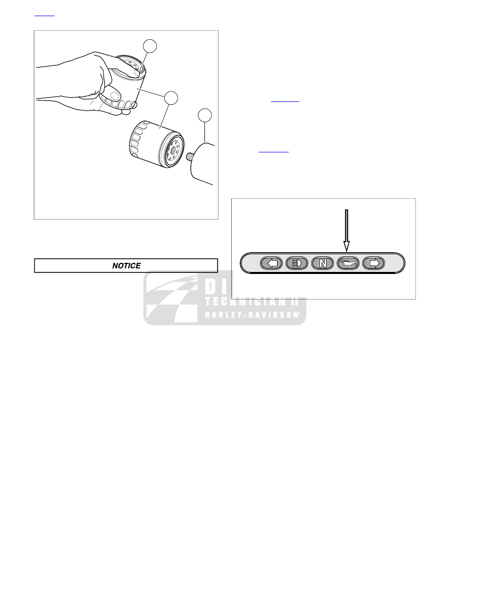
1. Thin film of oil ONLY
2. Oil filter
3. Mounting plate

Figure 1-7. Applying Thin Oil Film

Refilling Oil Tank

Do not overfill oil. Doing so can result in oil carryover to
the air cleaner leading to equipment damage and/or
equipment malfunction. (00190b)

NOTE

Do not overfill the oil tank. The oil tank has a built-in pressure
relief valve. If the oil tank is overfilled, excessive pressure is
created in the oil tank. The pressure relief valve will open to
relieve the pressure and prevent damage to the oil tank.
Excessive oil due to overfilling will also be forced out the
pressure relief valve when it opens.

1.

Refer to

Table 1-2

Always use the proper grade of oil for

the lowest expected air temperature before the next regu-
larly scheduled oil change. Pour 2.0 qt (1.9 L) of oil into
engine oil tank.

2.

Install dipstick in oil tank. Verify cap is fully seated.

3.

See

Figure 1-8

. Start engine. Verify that oil pressure signal

lamp turns off when engine speed is 1000 rpm or above.
Turn engine off.

4.

Check for oil leaks at oil filter and oil tank drain hose.
Perform oil level hot check.

sm07562

Figure 1-8. Oil Pressure Indicator

HOME

1-18 2013 Sportster Service: Maintenance

1.7

AIR FILTER

XL MODELS EXCEPT XL 1200V

TORQUE VALUE

FASTENER

4.5-6.8 Nm

40-60

in-lbs

Air filter screw

4.1-6.8 Nm

36-60

in-lbs

Air cleaner cover screw

Removal

1.

See

Figure 1-9

. Remove the two fasteners (1) and the trim

insert (2) from the air cleaner cover (3).

2.

Remove the air cleaner cover from the backplate. Remove
air cleaner seal (4) from the cover.

3.

Remove three fasteners (5). Remove the air filter (6) and
the gasket (7) from the backplate. Discard the gasket.

4.

Inspect the O-rings. Replace as necessary.

5.

Inspect the cover seal. Replace as necessary.

6.

Clean the air cleaner backplate.

7.

Clean the inside of air cleaner cover.

Install air filter before running engine. Failure to do so can
draw debris into the engine and could result in engine
damage. (00207a)

Installation

1.

See

Figure 1-9

. Apply a thin coat of engine oil or light

grease to the O-rings (8).

2.

Position a

new

gasket (7) on the air cleaner. Line up the

gasket holes with the backplate holes.

NOTE

Install the air filter with THIS SIDE OUT on top.

3.

Apply a drop of LOCTITE 243 MEDIUM STRENGTH
THREADLOCKER AND SEALANT (blue) to each of three
air filter fasteners (5). Install the air filter (6) onto the
backplate. Tighten to 40-60

in-lbs

(4.5-6.8 Nm).

4.

Fit air cleaner seal (4) onto air cleaner cover (3). Verify
alignment around cover edge.

5.

Install air cleaner cover onto backplate. Do not pinch or
distort seal.

6.

Install trim insert (2) and cover assembly with fasteners
(1). Tighten to 36-60

in-lbs

(4.1-6.8 Nm).

6

8

3

7

2

4

1

5

sm03384a

1. Fastener
2. Trim insert
3. Air cleaner cover
4. Air cleaner seal
5. Fastener
6. Air filter element
7. Gasket
8. O-ring

Figure 1-9. Air Filter Element: XL Models except XL 1200V

XL 1200V

TORQUE VALUE

FASTENER

4.5-6.8 Nm

40-60

in-lbs

Air filter screw

4.1-6.8 Nm

36-60

in-lbs

Air cleaner cover screw

Removal

1.

See

Figure 1-10

. Remove the fastener (1) from the air

cleaner cover (2).

2.

Remove the cover from the backplate. Remove air cleaner
seal (3) from the cover.

3.

Remove three fasteners (4). Remove the air filter (5) from
the backplate.

4.

Inspect the O-rings. Replace as necessary.

5.

Inspect the cover seal. Replace as necessary.

6.

Clean the air cleaner backplate.

7.

Clean the inside of air cleaner cover.

Install air filter before running engine. Failure to do so can
draw debris into the engine and could result in engine
damage. (00207a)

HOME

2013 Sportster Service: Maintenance 1-19

Installation

1.

Apply a thin coat of engine oil to the O-rings (6).

2.

Install a

new

gasket (7) on the air cleaner. Line up the

gasket holes with the backplate holes.

NOTE

Install the filter (5) with THIS SIDE OUT on top.

3.

See

Figure 1-10

Apply a drop of LOCTITE 243 MEDIUM

STRENGTH THREADLOCKER AND SEALANT (blue) to
each of three air filter fasteners (4).

4.

Install the air filter onto the backplate. Tighten to 40-60

in-lbs

(4.5-6.8 Nm).

5.

Fit air cleaner seal (3) onto air cleaner cover (2). Verify
alignment around cover edge.

6.

Install air cleaner cover onto backplate. Do not pinch or
distort seal.

7.

Install cover. Tighten to 36-60

in-lbs

(4.1-6.8 Nm).

4

2

5

1

3

6

7

sm07433

1. Screw
2. Cover
3. Seal
4. Screw (3)
5. Filter
6. O-ring
7. Gasket

Figure 1-10. Air Filter Element: XL 1200V

XR 1200X

Removal

Stop the engine when refueling or servicing the fuel
system. Do not smoke or allow open flame or sparks near
gasoline. Gasoline is extremely flammable and highly
explosive, which could result in death or serious injury.
(00002a)

1.

Remove the fuel tank. See

4.5 FUEL TANK: XR 1200X

.

2.

Remove the air box. See

1.7 AIR FILTER, XR 1200X

.

3.

See

Figure 1-11

Remove the two screws (2, 3) securing

the air filter cover (4) to air box (1).

4.

Using a small flat blade screwdriver, gently pry two button
head clips (5) securing air filter cover to air box. Discard
button head clips.

5.

See

Figure 1-12

Gently pull rear end of air filter cover (2)

away from air box. Disengage front of air filter cover from
the air box and set the cover aside.

6.

See

Figure 1-13

Using a flat blade screwdriver, gently

pry the lower front corner of the filter (2) out of the air box.
Work screwdriver around bottom of filter gasket (4) to free
the filter.

7.

Carefully pull the filter out of the air box.

8.

Clean the inside of the air box housing and cover.

9.

Inspect the air filter seal. Replace if necessary.

5

1

2

5

4

3

sm06726

1. Air box assembly
2. Screw
3. Screw
4. Air filter cover
5. Button head clip (2)

Figure 1-11. Unbolting Air Filter Cover

HOME

1-20 2013 Sportster Service: Maintenance

1

2

3

sm04934

1. Air box assembly
2. Air filter cover
3. Air filter element

Figure 1-12. Removing Air Filter Cover

1

2

3

4

sm04935

1. Air box assembly
2. Air filter element
3. Screwdriver
4. Gasket (built into air filter element)

Figure 1-13. Removing Air Filter Element

Installation

1.

See

Figure 1-13

Form a

new

air filter into a curved shape.

Slide top of air filter up into opening in air box. Top of the
air filter must fit into channel in top of air box.

2.

Press bottom and ends of air filter into air box. The air filter
must fit into the air box opening.

3.

See

Figure 1-12

. Position front of air filter cover (2) onto

air box. Do not install button head clips at this time.

4.

Active Intake Models:

See

Figure 1-15

.

a.

Verify that the active intake connector wiring harness
(4) is in the air box recess (5).

b.

Position the breather hose assembly inside the to air
box. The breather hose cannot interfere with the active
air solenoid flapper.

NOTE

Do not pinch the active intake connector wiring harness with
the air filter cover.

5.

Install rear of air filter cover (2) onto air box. Secure with
two screws.

6.

Install

new

button head clips. Press in firmly.

7.

Install the air box. See

1.7 AIR FILTER, XR 1200X

.

8.

Install the fuel tank. See

4.5 FUEL TANK: XR 1200X

.

sm04937

Figure 1-14. Filter Element Channel

HOME

2013 Sportster Service: Maintenance 1-21

3.23

OIL FILTER MOUNT

GENERAL

Oil is pressure-fed from the oil pump to the oil filter mount via
a hose connection. Oil travels through the filter mount into the
filter via outer filter holes.

Adequate oil pressure activates the oil pressure indicator lamp
switch in the filter mount, which turns off the oil pressure
indicator lamp.

The check ball in the filter adapter opens at:

XL Models:

10-13 psi (69-90 kPa) oil pressure.

XR 1200X:

5-7 psi (34-48 kPa) oil pressure.

Filtered oil leaves the filter, flowing past the check ball.

DISASSEMBLY

1.

Remove oil filter. See

1.6 ENGINE OIL AND FILTER

.

2.

See

Figure 3-172

. Remove oil filter adapter (1) from oil

filter mount (2).

3.

Remove check ball (3) and spring (4).

CLEANING AND INSPECTION

Compressed air can pierce the skin and flying debris from
compressed air could cause serious eye injury. Wear
safety glasses when working with compressed air. Never
use your hand to check for air leaks or to determine air
flow rates. (00061a)

Thoroughly clean all parts in cleaning solvent. Blow out holes
and passages using compressed air.

ASSEMBLY

TORQUE VALUE

FASTENER

24.4-29.8 Nm

18-22 ft-lbs

Oil filter adapter

NOTE

Use TEFLON PIPE SEALANT or HYLOMAR GASKET AND
THREAD SEALANT on all fittings installed to oil filter mount.

1.

See

Figure 3-172

Place spring (4) and check ball (3) into

threaded hole at center of mount (2). Push oil filter adapter
against ball to compress spring.

2.

Install threaded end with LOCTITE 242 MEDIUM
STRENGTH THREADLOCKER into threaded hole. Tighten
oil filter adapter to 18-22 ft-lbs (24.4-29.8 Nm).

3.

Install oil filter. Fill oil tank with proper oil. See

1.6 ENGINE

OIL AND FILTER, Changing Oil and Filter

.

3

4

2

5

2

1

1

sm03432

1. Oil filter adapter
2. Oil filter mount (part of right crankcase housing)
3. Check ball
4. Spring
5. Oil pressure indicator lamp switch

Figure 3-172. Oil Filter Mount, Typical (XL model shown)

HOME

3-120 2013 Sportster Service: Engine

3.24

OIL TANK

PRESSURE RELIEF VALVE

The oil tank has a pressure relief valve in the top of the tank.
If the vent line is pinched, restricted or if the tank is overfilled,
excessive pressure is created. The valve opens if the pressure
in the tank exceeds 10 psi (68.9 kPA).

OIL LINE ROUTING: XL MODELS

See

Figure 3-173

. The feed, vent and return ports are located

on the bottom of the oil tank to reduce under seat congestion.
An oil line routes the oil from the feed port at the lower right
front corner to a fitting on the oil pump.

From the feed section of the oil pump, another feed line directs
the flow up to the oil filter mount. Eventually, oil drains to the
sump where it collects in the scavenge section of the oil pump.
The return line routes the oil back to the tank where the cycle
is repeated.

4

2

1

3

5

sm06812c

1. Oil pump
2. Oil feed line
3. Return oil line
4. Feed oil line
5. Vent line

Figure 3-173. Engine Hose Routing: XL Models

OIL LINE ROUTING: XR 1200X

See

Figure 3-174

. The feed, vent and return ports are located

on the bottom of the oil tank to reduce under seat congestion.
An oil line routes the oil from the feed port at the lower right
front corner to a fitting on the oil pump.

Oil travels to the feed pump through an internal passage in the
pump housing. The feed pump pushes oil to the oil cooler, oil
filter, and cylinder heads. Oil used for lubricating internal engine
components eventually drains into the sump. Here the scav-
enge pump collects it and routes it back to the oil tank. The oil
from the cylinder heads and from the scavenge pump is
returned to the oil tank. See

3.6 ENGINE LUBRICATION

SYSTEM, Oil Flow: XR 1200X

.

2

5

8

10

1

10

5

4

9

3

9

2

7

3

10

9

7

sm06820b

6

1. Vent line
2. Return oil to tank
3. Oil feed line
4. Return oil manifold
5. Rear cylinder head return oil line
6. Return oil from pump
7. Cylinder head feed oil lines
8. Front cylinder head return oil line
9. Oil from oil cooler
10. Oil to oil cooler

Figure 3-174. Engine Oil Line Routing: XR 1200X

REMOVAL

1.

Remove seat.

2.

Remove left side cover. See

2.18 LEFT SIDE COVER

.

Prevent accidental vehicle start-up, which could cause
death or serious injury. First disconnect negative (-) battery
cable at engine and then positive (+) cable from battery.
(00280b)

3.

Disconnect negative (-) battery cable from ground stud on
crankcase. Disconnect positive (+) battery cables at bat-
tery.

4.

Drain oil tank. See

1.6 ENGINE OIL AND FILTER, Chan-

ging Oil and Filter

.

HOME

2013 Sportster Service: Engine 3-121

5.

Remove right side cover by gently prying bottom lip off
tab on oil tank. Then lift top of cover off two stanchions
molded into top of oil tank.

6.

Remove rear belt guard. See

2.22 BELT GUARD AND

DEBRIS DEFLECTOR

.

NOTE

For ease of assembly, mark oil tank lines, oil feed, drain, vent
and return, as they are removed from oil tank.

7.

Remove clamp and disconnect the drain line from oil tank.

8.

Remove clamp from upper end of feed oil line and discon-
nect line from oil tank.

9.

Remove clamp from upper end of the return oil line and
disconnect the line from oil tank.

10. Remove rear fender. See

2.33 REAR FENDER: ALL XL

MODELS EXCEPT XL 883N, XL 1200X/V

,

2.34 REAR

FENDER AND LICENSE PLATE BRACKET: XL 883N,
XL 1200X/V

or

2.35 REAR FENDER: XR 1200X

.

11. Remove clamp from upper end of vent oil line and discon-

nect line from oil tank.

12. Remove three screws and remove oil tank from right side

of motorcycle.

INSTALLATION

TORQUE VALUE

FASTENER

4.1-6.8 Nm

36-60

in-lbs

Oil tank mounting screw

1.

Slide oil tank into position in frame from right side of
vehicle.

2.

See

Figure 3-175

or

Figure 3-176

Install oil tank mounting

screw (3) through bracket (4) and loosely screw into oil
tank to hold tank in place.

3.

Install remaining two mounting screws through frame and
screw into oil tank. Tighten all three fasteners to 36-60

in-lbs

(4.1-6.8 Nm).

NOTES

All Models: The vent oil hose is composed of a flexible
hose originating at the gearcase cover elbow fitting, mated
to a hard plastic line, then another flexible hose at the oil
tank vent fitting.

XR 1200X: The return oil line is a manifold assembly that
branches between the crankcase and the rear cylinder
head.

4.

Install the oil vent hose (5), the feed hose (8), the drain
hose (9) and the return oil line (6) to the oil tank fittings.
Secure with

new

clamps.

5.

Install rear fender. See

2.33 REAR FENDER: ALL XL

MODELS EXCEPT XL 883N, XL 1200X/V

,

2.34 REAR

FENDER AND LICENSE PLATE BRACKET: XL 883N,
XL 1200X/V

or

2.35 REAR FENDER: XR 1200X

.

6.

Install rear belt guard. See

2.22 BELT GUARD AND

DEBRIS DEFLECTOR

.

7.

Install right side cover.

a.

Engage two holes on top of cover onto stanchions on
top of oil tank.

b.

Rotate bottom end of cover downward until bottom
lip of cover snaps in place on tab on bottom of oil
tank.

8.

Fill oil tank and install filler cap/dipstick. See

1.6 ENGINE

OIL AND FILTER, Checking and Adding Oil

.

Connect positive (+) battery cable first. If positive (+) cable
should contact ground with negative (-) cable connected,
the resulting sparks can cause a battery explosion, which
could result in death or serious injury. (00068a)

9.

Connect positive (+) battery cables to battery. Connect
negative (-) battery cable to ground point on engine
crankcase. See

1.22 BATTERY MAINTENANCE

.

10. Install left side cover.

After installing seat, pull upward on seat to be sure it is
locked in position. While riding, a loose seat can shift
causing loss of control, which could result in death or
serious injury. (00070b)

11. Install seat.

HOME

3-122 2013 Sportster Service: Engine


Content      ..     3      4      5      6     ..