Harley Davidson 2011 Touring Models. Service Manual - page 41
8
4
5
6
12
11
7
9
2
3
1
10
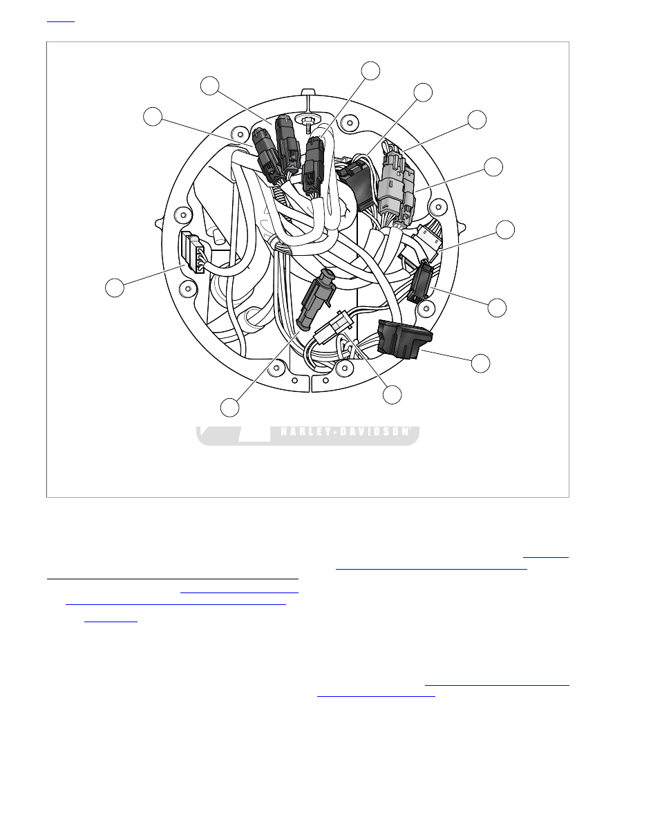
sm05159
7.
1.
Auxiliary lamps [73]
Right handlebar switches [22]
2.
8.
Left handlebar switches [24]
Auxiliary lamps switch [109]
9.
3.
Cruise on/off switch [158], FLHRC only
Front turn signals [31]
4.
10.
Front fender tip lamp [32], FLHR only
Cruise set/resume switch [159], FLHRC only
11.
5.
Front wheel speed sensor [167], ABS equipped
Headlamp [38]
6.
12.
Accessory switch [67]
TGS jumper harness [204]
Figure 7-107. Headlamp Nacelle- Main Harness Connectors (Road King models)
REMOVAL: FORK MOUNTED FAIRING
MODELS (PART 2)
1.
Remove outer fairing. See
WINDSHIELD: FORK MOUNTED FAIRING MODELS
.
2.
See
. Cut cable straps (4).
3.
Disconnect connectors and remove from their retaining
devices, if present:
a.
Twist grip sensor jumper harness (7).
b.
Main to interconnect harness (1).
c.
Main to interconnect harness (3).
d.
Radio antenna cable connector (5).
e.
Main to interconnect harness (2).
f.
Front wheel speed sensor (6) if equipped.
4.
Disconnect ignition switch connector. See
TION/LIGHT KEY SWITCH AND FORK LOCK
5.
Remove P-clamps securing main harnesses to steering
head.
6.
Carefully pull main harnesses rearward fairing cap and
allow to hang over top of engine guard.
7.
Disconnect rear audio harness connectors (8-11) if
equipped.
NOTE
Continue procedure at
.
7-84 2011 Touring Service: Electrical