Harley Davidson 2011 Touring Models. Service Manual - page 35
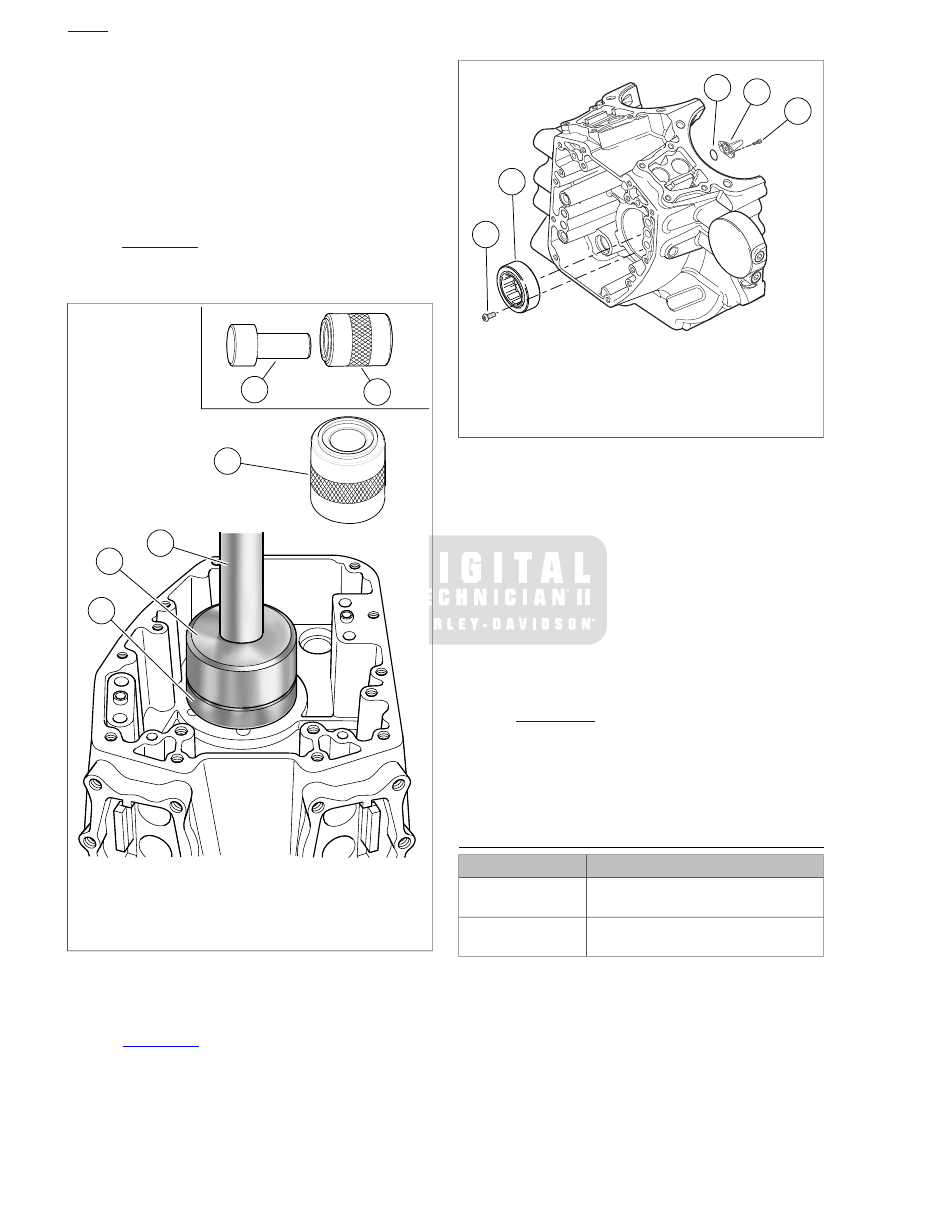
9.
Remove remover/installer and crankcase half from support
tube.
NOTES
•
Verify that the bearing is flush or slightly below the surface
of the crankcase. Never "push" the bearing into position
using the retaining screws.
•
If new retaining screws are not available, apply LOCTITE
THREADLOCKER 243 (blue) to threads of screws before
installation.
10. See
. Install two
new
main bearing retaining
screws (5) from the cam compartment side. Tighten screws
to 40-70
in-lbs
(4.5-7.9 Nm).
4
1
3
2
1
5
sm02304
1. Pilot/driver
2. Support tube
3. Ram
4. Main bearing
5. Support tube (2) "B" end up
Figure 3-126. Right Main Bearing Installation
Piston Jets Removal
1.
See
. Remove two screws (1) to free piston
jet (2) from crankcase.
2.
Remove O-ring (3) from groove in mounting flange of jet.
Discard O-ring.
1
4
5
2
3
sm02305a
1. Screw (2 each jet)
2. Piston jet (2)
3. O-ring (2)
4. Main bearing
5. Screw (2)
Figure 3-127. Piston Jets
Piston Jets Installation
NOTES
•
If piston jet is being reused, apply LOCTITE THREAD-
LOCKER 222 (purple) to threads of screws before install-
ation.
•
O-rings that are missing, distorted, pinched or otherwise
damaged will result in either oil leakage or low oil pressure.
Use of the wrong O-ring will have the same results. Since
many O-rings are similar in size and appearance, always
use new O-rings keeping them packaged until use to avoid
confusion.
1.
See
. Apply a very thin film of clean H-D
20W50 engine oil to
new
O-ring (3) for piston jet. Install
new
O-ring in groove of jet mounting flange.
2.
With jet pointed upward, start two screws (1) to secure
piston jet (2) to crankcase. Tighten to 25-35
in-lbs
(2.8-
3.9 Nm).
LEFT CRANKCASE HALF
TOOL NAME
PART NUMBER
CRANKCASE BEARING
REMOVER/INSTALLER
B-45655
CRANKCASE BEARING
REMOVER/INSTALLER BASE
HD-42720-5
Main Bearing Removal
NOTE
Never move or lift the crankcase by grasping the cylinder studs.
The crankcase is too heavy to be carried in this manner and
could be dropped.
3-92 2011 Touring Service: Engine