Harley Davidson FLHRC 2006. Maintenance & Repair Manual - page 39
HOME
TSM/TSSM VEHICLE DELIVERY
3.3
At certain steps in the programming sequence, the motorcy-
GENERAL
cle may provide confirmation of settings by flashing the turn
signals, turn signal indicators and/or security lamp. In addi-
tion, when programming a personal code into a TSSM sys-
1WARNING
tem, the odometer displays the personal code to the user and
dynamically updates it as the code is entered or changed.
Only Touring Harley-Davidson Motorcycles are suitable
for sidecar use. Consult a Harley-Davidson dealer. Use of
All programming operations are listed in table format. Follow
motorcycles other than Touring models with sidecars
the numbered steps to configure the system. If a confirmation
could result in death or serious injury. (00040a)
response is listed, wait for the confirmation before continuing
to the next step. Important information pertaining to certain
Setting up a vehicle TSM/TSSM depends on whether the
actions will be found in the NOTES column.
vehicle has a turn signal module (TSM) or the optional secu-
rity system (TSSM) installed.
SIDECAR CONFIGURATION
All motorcycles ship with the TSM/TSSM set for use without
a sidecar installed. If a motorcycle is equipped with a TSM, no
further configuration is required. However, if a motorcycle has
1WARNING
an optional security system (TSSM) installed, perform the fol-
lowing steps as necessary.
Only Touring Harley-Davidson Motorcycles are suitable
for sidecar use. Consult a Harley-Davidson dealer. Use of
1.
Configure TSSM motorcycles by assigning both key fobs
motorcycles other than Touring models with sidecars
to the vehicle.
could result in death or serious injury. (00040a)
2.
Configure TSSM motorcycles by entering a personal
On motorcycles equipped with a sidecar, the TSM/TSSM
code picked by the owner. The personal code allows the
must be switched from the factory solo vehicle setting to the
owner to operate the system if the key fob is lost or inop-
sidecar setting using a computer based diagnostic package
erable. Record this code in the owner’s manual and
called DIGITAL TECHNICIAN (Part No. HD-44750) and a
instruct the customer to carry a copy.
BAS kit must then be installed. If the sidecar is then perma-
nently removed, the TSM/TSSM must be reconfigured back
IMPORTANT NOTE
to the solo setting and the BAS kit removed. To verify whether
Do not forget to enter a personal code for TSSM vehicles.
the TSM/TSSM is configured for solo or sidecar usage, refer
If a code is not assigned and both key fobs are lost or
to Table 3-1.
damaged while the vehicle is armed, the TSSM and ECM/
ICM must be replaced.
POWER DISRUPTION AND
Changes to TSM/TSSM settings are made by a series of pro-
CONFIGURING
gramming operations involving the ignition key, left/right turn
signal switches and key fob (security systems).
The TSM/TSSM will not enter configuration mode on the first
attempt after battery voltage has been removed from terminal
1. This will occur after any of the following situations:
● Battery disconnect or power drain.
● Battery fuse or maxi-fuse removal.
● Connecting Breakout Box to TSM/TSSM connector.
Therefore, after all battery reconnects, the configuration
sequence must be modified as follows.
1.
Set run switch to OFF, cycle ignition key ON-OFF-ON-
OFF-ON and press left turn signal switch twice.
2.
Repeat step listed above.
3.
Continue with configuration sequence listed.
2006 Touring: TSM & TSSM
3-5
HOME
Decide what five digit code the owner would like to use. The
KEY FOB ASSIGNMENT
code will be programmed using the turn signal switches and
key fob. Keep a record of the code in a secure place such as
The key fob on TSSM motorcycles must be set so it will oper-
your wallet or the owner’s manual.
ate the alarm system on the vehicle. This assignment must
be completed with no pauses between steps greater than 10
● When programming the personal code, the security lamp
seconds. Turn the ignition OFF after all key fobs have been
flashes to provide feedback when entering each digit.
assigned. The programming mode will also exit after 60 sec-
The odometer also displays the PIN and the change
onds has elapsed without detecting any fob signup messages
dynamically.
or turn signal switch activity.
● The number of security lamp flashes corresponds to the
number currently selected for a given digit. Therefore, the
Two key fobs may be assigned to the TSSM. The first suc-
cessful attempt to program a fob will disable all previously
lamp may flash 1-9 times depending on the number
assigned fobs. If a second fob is to be programmed, it must
entered. The five-digit code will change on the odometer
be done in the same programming sequence as the initial fob.
display and the active digit will blink.
● Press the left turn switch one time to increment each
To assign a key fob to a motorcycle, refer to Table 3-2.
digit of the code.
● Quickly press the key fob button twice to advance to the
PERSONAL CODE ENTRY
next digit of the code.
NOTE
First Time Code Entry: TSSM Only
The programming mode exits upon turning the ignition switch
to OFF or if no turn signal switch/key fob button activity
IMPORTANT NOTE
occurs for 60 seconds. No data is saved for partial configura-
tion attempts if entering a PIN for the first time. If a PIN has
Do not forget to enter a personal code for TSSM vehicles.
previously been entered, the user can change any digit or
If a code is not assigned and both key fobs are lost or
group of digits.
damaged while the vehicle is armed, the TSSM must be
replaced.
Modifying Existing Codes: TSSM Only
The TSSM personal code (Personal Identification Number or
PIN) consists of five digits. Each digit can be any number
If a code was previously entered, the security lamp will flash
from 1-9. The personal code must be used to disarm the
the equivalent digit, and the odometer will display the existing
security system in case the key fob becomes unavailable.
code with the active digit blinking. Each additional press of
the left turn switch will increment the digit.
To set a personal code on a motorcycle with no code previ-
ously installed, refer to Table 3-3. The procedure listed uses
● To advance from 5 to 6, press and release the left turn
3-1-3-1-3 as the desired personal code.
switch 1 time.
● To advance from 8 to 2, press and release the left turn
NOTE
switch 3 times (9-1-2).
For better security, do not use 3-1-3-1-3 as a personal code.
It is shown as an example only.
3-6
2006 Touring: TSM & TSSM
HOME
Table 3-1. Verifying Whether TSM/TSSM is Configured for Solo/Sidecar* Use
NO.
ACTION
WAIT FOR CONFIRMATION
NOTES
Verify that security lamp is
1
Set RUN/OFF switch to OFF
not blinking (vehicle is dis-
armed)
2
Turn IGN key ON-OFF-ON-OFF-ON
1 flash-Worldwide TSM, no
security
1-4 flashes turn signals & indicators
2 flashes-North American/
depending on vehicle configuration
Press left turn switch 2 times and
Domestic configurationTSSM
3
(See Section 3.3 TSM/TSSM VEHICLE
release
3 flashes-Netherlands config-
DELIVERY regarding battery discon-
uration TSSM
nects.)
4 flashes-European/HDI con-
figuration TSSM
Press right turn switch 1 time and
4
1 flash turn signals & indicators
release
Press right turn switch 1 time and
5
2 flashes turn signals & indicators
release
1-2 flashes turn signals & indicators
1 flash-Solo
6
Press left turn switch 1 time and release
depending on vehicle configuration
2 flashes-Sidecar
7
Turn IGN key OFF
* Only Touring models can be configured for sidecar usage and then access to Digital Technician is required.
Table 3-2. TSSM Key Fob Assignment
NO.
ACTION
WAIT FOR CONFIRMATION
NOTES
Verify that security lamp is
not blinking (vehicle is dis-
armed)
1
Set RUN/OFF switch to OFF
This assignment procedure
must be completed with no
pauses between steps
greater than 10 seconds
2
Turn IGN key ON-OFF-ON-OFF-ON
1 flash-Worldwide TSM, no
security
1-4 flashes turn signals & indicators
2 flashes-North American/
depending on vehicle configuration
Domestic configuration
Press left turn switch 2 times and
3
TSSM
(See Section 3.3 TSM/TSSM VEHICLE
release
DELIVERY regarding battery discon-
3 flashes-The Netherlands
nects.)
configuration TSSM
4 flashes-European/HDI con-
figuration TSSM
Press right turn switch 1 time and
4
1 flash turn signals & indicators
release
5
Press left turn switch 1 time and release
2 flashes turn signals & indicators
Press and hold key fob button until
6
2 flashes turn signals & indicators
This may take 10-25 seconds
confirmation is received
If you have two key fobs, press and hold
7
button on second key fob until
2 flashes turn signals & indicators
optional step
confirmation is received
8
Turn IGN key OFF
2006 Touring: TSM & TSSM
3-7

HOME
Table 3-3. Programming A TSSM Personal Code (Example: 3-1-3-1-3)
With No Code Previously Installed
NO.
ACTION
WAIT FOR CONFIRMATION
NOTES
Verify that security lamp is
not blinking (vehicle is dis-
armed)
1
Set RUN/OFF switch to OFF
This assignment procedure
must be completed with no
pauses between steps
greater than 10 seconds
2
Turn IGN key ON-OFF-ON-OFF-ON
1 flash-Worldwide TSM, no
security
1-4 flashes turn signals and indicators
2 flashes-North American/
depending on vehicle configuration
Domestic configuration
Press left turn switch 2 times and
3
TSSM
(See Section 3.3 TSM/TSSM VEHICLE
release
DELIVERY regarding battery discon-
3 flashes-The Netherlands
nects)
configuration TSSM
4 European/HDI configura-
tion TSSM
One flash turn signals and indicators
Vehicle is in personal code
Quickly press key fob button 2 times
Odometer displays current five-digit per-
4
entry mode ready to enter or
and release
sonal code (five dashes if no code
modify first digit
entered), first digit blinks
Security lamp flashes 1 - 9 times if code
A lack of confirmation flashes
5
Press left turn switch 1 time and release
was previously entered
indicates no digit is entered
Blinking digit in odometer display incre-
Press and release left turn switch to
ments, security lamp flashes to indicate
advance through the digits
each digit selected
You’ve selected 3 as a num-
6
In this example, you will press and
In this example, the blinking digit dis-
ber for the first digit
release three times
played is 3 and the security lamp will
flash three times
You’ve confirmed 3 as a num-
Quickly press key fob button 2 times
Two flashes turn signals and indicators
ber for the first digit and have
7
and release
second digit in odometer display blinks
advanced to entering the
second digit
A lack of confirmation flashes
8
Press left turn switch 1 time and release
none
indicates no digit is entered
Blinking digit in odometer display incre-
Press and release left turn switch to
ments, security lamp flashes to indicate
advance through the digits
each digit selected
You’ve selected 1 as a num-
9
In this example, you will perform this step
In this example, the blinking digit dis-
ber for the second digit
one time
played is 1 and the security lamp will
flash one time
You’ve confirmed 1 as a num-
Quickly press key fob button 2 times
Three flashes turn signals and indicators
ber for the second digit and
10
and release
third digit in odometer display blinks
have advanced to entering
the third digit
A lack of confirmation flashes
11
Press left turn switch 1 time and release
none
indicates no digit is entered
3-8
2006 Touring: TSM & TSSM
HOME
Table 3-3. Programming A TSSM Personal Code (Example: 3-1-3-1-3)
With No Code Previously Installed
NO.
ACTION
WAIT FOR CONFIRMATION
NOTES
Blinking digit in odometer display incre-
Press and release left turn switch to
ments, security lamp flashes to indicate
advance through the digits
each digit selected
You’ve selected 3 as a num-
12
In this example, you will repeat this step
In this example, the blinking digit dis-
ber for the third digit
three times
played is 3 and the security lamp will
flash three times
You’ve confirmed 3 as a num-
Quickly press key fob button 2 times
Four flashes turn signals and indicators
ber for the third digit and
13
and release
fourth digit in odometer display blinks
have advanced to entering
the fourth digit
A lack of confirmation flashes
14
Press left turn switch 1 time and release
none
indicates no digit is entered
Blinking digit in odometer display incre-
Press and release left turn switch to
ments, security lamp flashes to indicate
advance through the digits
each digit selected
You’ve selected 1 as a num-
15
In this example, you will perform this step
In this example, the blinking digit dis-
ber for the fourth digit
one time
played is 1 and the security lamp will
flash one time
You’ve confirmed 1 as a num-
Quickly press key fob button 2 times
Five flashes turn signals and indicators
ber for the fourth digit and
16
and release
fifth digit in odometer display blinks
have advanced to entering
the fifth digit
A lack of confirmation flashes
17
Press left turn switch 1 time and release
none
indicates no digit is entered
Blinking digit in odometer display incre-
Press and release left turn switch to
ments, security lamp flashes to indicate
advance through the digits
each digit selected
You’ve selected 3 as a num-
18
In this example, you will repeat this step
In this example, the blinking digit dis-
ber for the fifth digit
three times
played is 3 and the security lamp will
flash three times
You’ve confirmed 3 as a num-
Quickly press key fob button 2 times
One flash turn signals and indicators
19
ber for the fifth digit and have
and release
first digit in odometer display blinks
gone back to the first digit
20
Turn IGN key OFF
21
Write down code in owner’s manual
Arm the security system and attempt to
22
disarm using personal code entry. Refer
to Table 3-9.
2006 Touring: TSM & TSSM
3-9
HOME
TSM/TSSM TURN SIGNAL FUNCTIONS
3.4
● The turn signals will cancel within two seconds upon turn
GENERAL
completion. A sensor inside the TSM/TSSM cancels the
signal after the vehicle has been returned to an upright
The TSM/TSSM’s turn signal feature has several modes:
position.
● Automatic cancellation.
NOTE
● Manual cancellation.
The bank angle cancellation function has an automatic cali-
● Four-way flashing.
bration feature. Ride the motorcycle for 1/4 mile (0.4 KM) at
steady speeds (upright) to calibrate the system. Performance
● Diagnostics mode.
of bank angle function may not be optimal until this calibration
The turn signals cannot be activated or deactivated when the
is performed. This self-calibration is performed automatically
ignition key is in the ACC position. The turn signals can only
every time the vehicle is started and ridden.
be activated or deactivated with the ignition key in the IGN
position.
MANUAL CANCELLATION
1WARNING
If you want to stop the turn signals from flashing, briefly
Only Touring Harley-Davidson Motorcycles are suitable
depress the turn signal switch a second time.
for sidecar use. Consult a Harley-Davidson dealer. Use of
motorcycles other than Touring models with sidecars
If you are signalling to turn in one direction and you depress
could result in death or serious injury. (00040a)
the switch for the opposite turn signal, the first signal is can-
celled and the opposite side begins flashing.
AUTOMATIC CANCELLATION
Press the left or right turn switch to activate automatic turn
signal cancellation. There is no need to hold the turn switch in
when approaching the turn. The TSM/TSSM will not cancel
the signal before the turn is actually completed.
● When the directional switch is released, the system
starts a 20 count. As long as the vehicle is traveling
above 7 MPH (11.3 KPH) the directional will always can-
cel after 20 flashes if the system does not recognize any
other input.
● If the vehicle speed drops to 7 MPH (11.3 KPH) or less,
including stopped, the directionals will continue to flash.
Counting will resume when vehicle speed reaches 8
MPH (12.9 KPH) and will automatically cancel when the
count total equals 20 as stated above.
3-10
2006 Touring: TSM & TSSM
HOME
FOUR-WAY FLASHING
DIAGNOSTICS MODE
Use the following method to activate the four-way flashers.
The TSM/TSSM measures the current when the turn signals
are used. If there is a burned out light bulb on one side, the
1.
With the ignition key ON and security system disarmed
remaining light and the corresponding turn signal indicator
(models with security only), press the left and right turn
flash at double the normal rate starting with the fifth flash.
signal switches at the same time.
Other diagnostic conditions monitored include:
2.
Turn the ignition key OFF and arm the security system if
present and desired. The four-way flashers will continue
● Short circuit in the turn signal wiring.
for two hours.
● Open circuit in the turn signal wiring.
3.
To cancel four-way flashing, disarm the security system if
● Stuck turn signal switch.
necessary, turn the ignition key ON and press the left
and right turn signal switches at the same time.
NOTES
● A stuck turn signal switch will disable the automatic turn
NOTE
signal cancellation feature.
Auto-arming (always active on The Netherlands bikes, user
selectable on other vehicles) requires that the four-way flash-
● If a stuck switch is detected, you must hold the left and
ers be activated within 30 seconds of key OFF or after the
right turn signal switches in for more than one second to
vehicle has been disarmed.
activate the four-way flashers.
This system allows a stranded vehicle to be left in the four-
See Section 3.8 CHECKING FOR DIAGNOSTIC TROUBLE
way flashing mode and secured until help is found.
CODES for more information.
If the security system is disarmed while the four-way flashers
are active, the lights will flash as follows:
1.
TSSM stops four-way flashing mode. Motorcycle sits for
1 second with turn signals off.
2.
TSSM performs disarming confirmation (1 flash).
3.
Motorcycle sits for 1 second with turn signals off.
4.
Motorcycle restarts four-way flashing mode.
2006 Touring: TSM & TSSM
3-11
HOME
TSM/TSSM BANK ANGLE FUNCTION
3.5
GENERAL
OPERATION
The engine will shut off automatically if the vehicle tilts more
The turn signals, starter motor, ICM (carbureted models),
than 45 degrees from vertical for longer than one second. The
ECM (EFI models), fuel pump (EFI models) and coil will be
engine will automatically shut off even if the tilt occurs at a
disabled in the event the vehicle tilts more than 45° from verti-
very slow speed. The odometer displays “tIP” when a tip over
cal for longer than one second.
condition is detected.
To restart the motorcycle after shutdown has occurred:
1WARNING
1.
Return the motorcycle to an upright position.
Only Touring Harley-Davidson Motorcycles are suitable
2.
Cycle the ignition key OFF-ON before restarting the vehi-
for sidecar use. Consult a Harley-Davidson dealer. Use of
cle.
motorcycles other than Touring models with sidecars
could result in death or serious injury. (00040a)
If a sidecar is installed, install Sidecar BAS Kit (Part No.
88115-03) and reconfigure the TSM/TSSM using Digital
Technician.
3-12
2006 Touring: TSM & TSSM
HOME
SECURITY SYSTEM (TSSM) FUNCTIONS
3.6
Default settings for the TSSM include:
GENERAL
● Solo vehicle configuration.
● High motion sensitivity on alarm sensitivity.
Security System Operation
● Default auto-arming behavior depends upon vehicle mar-
The TSSM provides security and immobilization functions not
ket. All vehicles are shipped without atuo-arming. Vehi-
found on the TSM. The TSSM will disable the starter and igni-
cles delivered to The Netherlands market require auto-
tion system. Additional functions include the ability to alter-
arming activation using Digital Technician. Motorcycles
nately flash the left and right turn signals and sound a siren (if
sold in other markets have auto-arming disabled, but it
purchased as an option) if a theft attempt is detected.
may be activated.
● Storage mode set to 20 days.
Conditions that activate the security system when system is
armed include:
Differences By Market Specifications
● Detecting tampering of the ignition circuit: Turn sig-
The Netherlands TSSM set-up differs from other TSSM set-
nals flash three times, optional siren chirps once and
ups in the following ways:
then turns off. If the tampering continues, a second warn-
ing will activate after four seconds. Continued tampering
● The Netherlands configuration always auto-arms itself
will cause the alarm to activate for 30 seconds and then
within 30 seconds after the ignition key is turned OFF.
turn off. The two warnings/alarm cycle is repeated for
● The Netherlands version does not have the remote arm-
each tampering incident.
ing only option.
● Detecting vehicle movement: Turn signals flash three
times, optional siren chirps once and then turns off. If the
ALARM SENSITIVITY
vehicle is not returned to its original position, a second
warning will activate after four seconds. If the vehicle is
not returned to its original position, the alarm activates
for 30 seconds then turns off. The two warnings/alarm
Sensitivity
cycle may repeat a maximum of 10 times.
The TSSM has four sensitivity settings: extremely low, low,
● Detecting tampering of the security lamp circuit: Turn
medium or high. The selection picked controls the sensitivity
signals flash three times, optional siren chirps once and
of the security system in regards to motion detection.
then turns off. If the tampering continues, a second warn-
To set alarm sensitivity, refer to Table 3-4.
ing will activate after four seconds. Continued tampering
will cause the alarm to activate for 30 seconds and then
Transport Mode
turn off. The two warnings/alarm cycle repeats once for
each tampering incident.
It is possible to arm the security system without enabling the
motion detector for one ignition cycle. This allows the vehicle
● Detecting that a battery or ground disconnect has
to be picked up and moved in an armed state. In this mode,
occurred while armed. Siren, if installed, activates its
any attempt to hot-wire the vehicle will trigger the security
self-alarm mode. Turn signals will not flash.
system.
See Section 3.7 ARMING/DISARMING SECURITY SYSTEM
● To enter the transport mode, refer to Table 3-5.
(TSSM) for more information.
● To exit from transport mode and return the system to nor-
NOTE
mal operation/functions, disarm the system using either
the key fob or personal code.
Always disarm the TSSM before removing or disconnecting
the battery to prevent the siren (if installed) from activating. If
NOTE
the TSSM is in auto-arming mode, you must disarm the sys-
tem using two clicks of the key fob and disconnect the battery
Transport mode is especially useful when working on The
or remove the battery fuse before the 30 second arming
Netherlands vehicles. If it is not used, the alarm will activate
period expires.
under many typical service activities.
Security System Options
The following customization options are only available on the
TSSM unit: alarm sensitivity, auto-arming feature and storage
mode.
2006 Touring: TSM & TSSM
3-13

HOME
AUTO-ARMING FUNCTION
STORAGE MODE
Auto-arming causes the system to automatically arm itself
The TSSM has a special mode for long term storage. This
(no key fob needed) within 30 seconds after the ignition key is
mode prevents the security system from draining the battery
turned OFF. During this period, the security lamp stays on
after a period of days (10, 20, 60 or infinite) without any igni-
solid to indicate auto-arming is starting up.
tion key switch activity.
The vehicle may be moved during these 30 seconds without
● If the TSSM is set to infinite, the system will not go into
triggering the alarm. However, any motion after that period
storage mode.
will trigger the security alarm. Upon expiration of the auto-
● Vehicles will enter storage mode whether the security
arming period, the turn signals flash twice, the security lamp
system is armed or disarmed.
begins to flash and the siren (if installed) chirps twice.
● If set to 20 days or greater, the customer must use an
The TSSM allows remote arming via the key fob at any time.
approved trickle charger to keep the battery from dis-
However, if the system is remotely disarmed (with the key
charging.
fob) but the ignition key is not turned ON within 30 seconds,
the system will rearm itself when auto-arming is enabled.
In storage mode, all alarm functions remain active but the
receiver is shut down and will not respond to the key fob. The
The auto-arming setting depends upon vehicle market speci-
vehicle is immobilized because the starter motor and ECM
fications.
are disabled. When the storage mode is entered, the security
lamp stops flashing to conserve power.
● Domestic and HDI motorcycles have auto-arming dis-
abled by default. However, the feature may be enabled if
To wake up the TSSM from storage mode, the ignition key
the customer desires.
must be turned ON. This will trigger a warning/alarm if the
system was previously armed. You must use the key fob or
● Vehicles sold in The Netherlands have auto-arming
personal code to disarm the system and stop the alarm.
enabled and this setting cannot be changed.
To set the storage mode preferences, refer to Table 3-7.
When auto-arming is disabled, the key fob must be used to
arm the security system.
To set the auto-arming function, if it is available on your vehi-
cle, refer to Table 3-6.
Table 3-4. TSSM Alarm Sensitivity
NO.
ACTION
WAIT FOR CONFIRMATION
NOTES
Verify that security lamp is
1
Set RUN/OFF switch to OFF
not blinking (vehicle is dis-
armed)
2
Turn IGN key ON-OFF-ON-OFF-ON
2 flashes-North American/
2-4 flashes turn signals & indicators
Domestic configuration
depending on vehicle configuration
TSSM
Press left turn switch 2 times and
3
(See Section 3.3 TSM/TSSM VEHICLE
3 flashes-The Netherlands
release
DELIVERY regarding battery discon-
configuration TSSM
nects.)
4 European/HDI configura-
tion TSSM
Press and hold key fob button until
4
1 flash turn signals & indicators
confirmation is received
1 flash-extremely low
turn signals & indicators flash to indicate
2 flashes-low sensitivity
5
Press left turn switch 1 time and release
option selected
3 flashes-medium sensitivity
4 flashes-high sensitivity
1 flash-extremely low
Press and release left turn switch to
turn signals & indicators flash to indi-
2 flashes-low sensitivity
6
advance through options
cate option selected
3 flashes-medium sensitivity
4 flashes-high sensitivity
7
Turn IGN key OFF
3-14
2006 Touring: TSM & TSSM

HOME
Table 3-5. TSSM Transport Mode
NO.
ACTION
WAIT FOR CONFIRMATION
NOTES
Verify that security lamp is
1
Set RUN/OFF switch to OFF
not blinking (vehicle is dis-
armed)
2
Turn IGN key ON
Press and hold key fob button until
3
3 flashes turn signals & indicators
confirmation is received
4
Turn IGN key OFF
Press and hold key fob button until
The vehicle can be moved
5
3 flashes turn signals & indicators
confirmation is received
without tripping the alarm
Table 3-6. Selecting TSSM Auto-arming Function
(Not Available on The Netherlands Vehicles)
NO.
ACTION
WAIT FOR CONFIRMATION
NOTES
Verify that security lamp is
1
Set RUN/OFF switch to OFF
not blinking (vehicle is dis-
armed)
2
Turn IGN key ON-OFF-ON-OFF-ON
2 flashes-North American/
2-4 flashes turn signals & indicators
Domestic configuration
depending on vehicle configuration
TSSM
Press left turn switch 2 times and
3
(See Section 3.3 TSM/TSSM VEHICLE
3 flashes-The Netherlands
release
DELIVERY regarding battery discon-
configuration TSSM
nects.)
4 European/HDI configura-
tion TSSM
Press and hold key fob button until
4
1 flash turn signals & indicators
confirmation is received
Press and hold key fob button until
5
2 flashes turn signals & indicators
confirmation is received
1 flash-
turn signals & indicators flash to indicate
auto-arming disabled
6
Press left turn switch 1 time and release
option selected
2 flashes-
auto-arming enabled
Press and release left turn switch to
turn signals & indicators flash to indicate
7
advance through options
option selected
8
Turn IGN key OFF
2006 Touring: TSM & TSSM
3-15

HOME
Table 3-7. TSSM Storage Mode Preferences
NO.
ACTION
WAIT FOR CONFIRMATION
NOTES
Verify that security lamp is
1
Set RUN/OFF switch to OFF
not blinking (vehicle is dis-
armed)
2
Turn IGN key ON-OFF-ON-OFF-ON
2 flashes-North American/
2-4 flashes turn signals & indicators
Domestic configuration
depending on vehicle configuration
TSSM
Press left turn switch 2 times and
3
(See Section 3.3 TSM/TSSM VEHICLE
3 flashes-The Netherlands
release
DELIVERY regarding battery discon-
configuration TSSM
nects.)
4 European/HDI configura-
tion TSSM
Press and hold key fob button until
4
1 flash turn signals & indicators
confirmation is received
Release and then hold key fob button
5
2 flashes turn signals & indicators
until confirmation is received
Release and then hold key fob button
6
3 flashes turn signals & indicators
until confirmation is received
1 flash-10 days
turn signals & indicators flash to indicate
2 flashes-20 days
7
Press left turn switch 1 time and release
option selected
3 flashes-60 days
4 flashes-Infinite
1 flash-10 days
Press left turn switch to advance through
turn signals & indicators flash to indicate
2 flashes-20 days
8
options
option selected
3 flashes-60 days
4 flashes-Infinite
9
Turn IGN key OFF
3-16
2006 Touring: TSM & TSSM
HOME
ARMING/DISARMING SECURITY SYSTEM (TSSM)
3.7
GENERAL
USING KEY FOB
There are two methods to arm the security system:
General
● Using the key fob.
● Using auto-arming. See Section 3.6 SECURITY SYS-
The TSSM’s reception range for the key fob signal depends
TEM (TSSM) FUNCTIONS.
on a specific receiver pattern.
NOTE
NOTE
The vehicle cannot be armed with the engine running or the
ignition ON.
Environmental and geographic conditions may affect signal
range.
There are two ways to disarm the system:
● Using the key fob. This method works in all situations
Arming the System
except before turning ignition key ON when TSSM stor-
age mode is activated.
1.
Hold key fob horizontal at waist level.
● Using the personal code.
2.
Point key fob at the front of the vehicle.
3.
Hold down the key fob button until the system responds
SECURITY LAMP
with two turn signal flashes.
Refer to Table 3-8. The security lamp within the speedometer
Disarming the System
provides feedback to the rider confirming armed or disarmed
status.
1.
Hold key fob horizontal at waist level.
2.
Point key fob at the front of the vehicle.
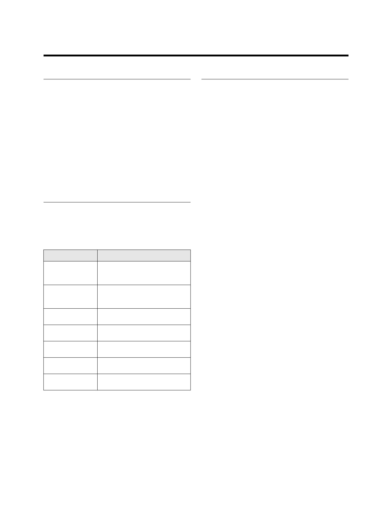
Table 3-8. Security Lamp Status
3.
Quickly press the key fob button twice. The system will
respond with one turn signal flash.
LAMP
MODE
No security system (TSM), security
NOTE
Does not flash
system not armed or storage mode
Disarming function may require practice. The key fob button
active
must be pressed twice within 1.5 seconds to send the disarm
command. The action is very similar to double-clicking a com-
10 minute timeout after failed per-
Flashes every
puter mouse. Light quick taps work best; very hard or very
sonal code entry attempt or a battery
second
slow taps are less likely to work.
reconnect has occurred while armed
Flashes every
Security system armed
Troubleshooting
2 seconds
Flashes 3 times
If the key fob button has been pressed numerous times while
Personal code entry mode
away from the vehicle, the fob may fall out of synchronization
a second
with the TSSM. If this happens, the TSSM might fail to recog-
Stays on solid with
Auto-arming is starting up. You have
nize the key fob’s commands.
ignition key OFF
30 seconds before system is armed.
To solve this problem, press and hold the key fob button for
Stays on solid with
If solid for more than 4 seconds after
10-15 seconds until the security system responds with two
ignition key ON
key ON, a current DTC is present
turn signal flashes. After confirmation, you may resume nor-
Four-way flashers
See Section 3.8 CHECKING FOR
mal fob operation.
flash 6 times (TSM)
DIAGNOSTIC TROUBLE CODES
2006 Touring: TSM & TSSM
3-17
HOME
USING THE PERSONAL CODE
Disarming the System
Refer to Table 3-9. If you make an error while disarming the
General
TSSM using the personal code, the alarm will activate for 30
seconds after the last digit is entered. After a failed attempt,
The personal code consists of five digits entered using the left
the security lamp will flash once every second for 10 minutes.
and right turn signal switches. Each digit can be any number
During this time, the vehicle will not accept any attempt
from 1-9. The personal code is intended to be used to disarm
to enter a personal code.
the vehicle in case the key fob becomes unavailable or inop-
erable.
See Section 3.3 TSM/TSSM VEHICLE DELIVERY to set a
personal code.
Table 3-9. Entering A Personal Code To Disarm TSSM (Example: 3-1-3-1-3)
NO.
ACTION
WAIT FOR CONFIRMATION
NOTES
1
Set RUN/OFF switch to OFF
2
Turn IGN key to ACC
Hold both turn switches in until
System is ready for personal
3
security lamp blinks at fast rate
confirmation
code entry
Enter first digit of code (3) by pressing
4
left turn switch 3 times
Serves as “enter” key for first
5
Press right turn switch 1 time
digit
Enter second digit of code (1) by press-
6
ing left turn switch 1 time
Serves as “enter” key for sec-
7
Press right turn switch 1 time
ond digit
Enter third digit of code (3) by pressing
8
left turn switch 3 times
Serves as “enter” key for third
9
Press right turn switch 1 time
digit
Enter fourth digit of code (1) by pressing
10
left turn switch 1 time
Serves as
“enter” key for
11
Press right turn switch 1 time
fourth digit
Enter fifth digit of code (3) by pressing
12
left turn switch 3 times
System is disarmed. You may
13
Press right turn switch 1 time
security lamp stops blinking
use the vehicle or program
another key fob
3-18
2006 Touring: TSM & TSSM
HOME
CHECKING FOR DIAGNOSTIC TROUBLE CODES
3.8
TSM
If the turn signals flash six four-way flashes shortly after key
ON, it indicates a DTC has been logged sometime in the last
three ignition cycles.
TSSM
To diagnose system problems, start by observing the behav-
ior of the security lamp.
NOTES
●
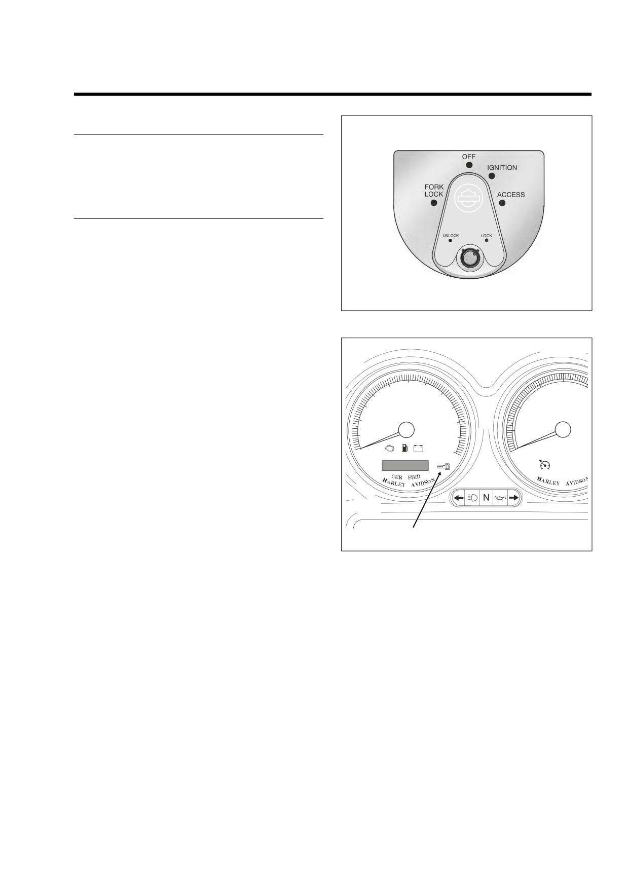
See Figure 3-7. “Key ON” means that the ignition key is
turned to IGNITION and the engine stop switch is set to
f2080x8x
RUN (although the engine is not running).
Figure 3-7. Ignition Switch (FLHX, FLHT/C/U, FLTR)
●
See Figure 3-8. When the ignition key is turned ON, the
security lamp will illuminate for approximately four sec-
onds and then turn off.
●
If the security lamp is not illuminated at Key ON or if it
fails to turn OFF after the initial four second period, the
speedometer may need to be replaced. See Section 3.10
60
40
50
70
30
50
SPEEDOMETER SELF DIAGNOSTICS. If “BUS Er” is
40
80
30
90
20
displayed on the odometer, it may take up to twenty sec-
MPH
RPM x100
onds for the security lamp to illuminate.
20
100
10
10
110
●
The security lamp will also light for eight seconds after
0
120
0
the bulb check if historic DTC’s are present. The security
lamp will stay on if current DTC’s are set. If a historic
DTC is present, the security lamp will light for 50 ignition
TI
-D
-D
cycles or until the DTC is cleared manually.
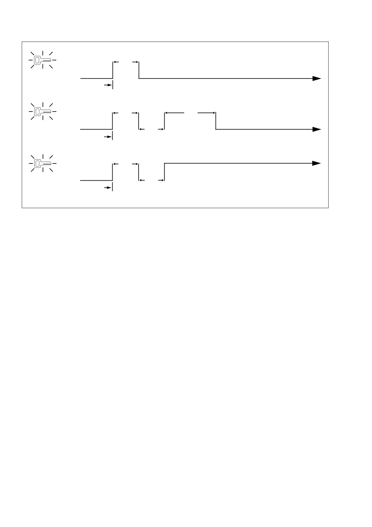
1.
See Figure 3-9. After the lamp turns off after being illumi-
nated for the first four second period, one of three events
may occur:
Security Lamp
f2160x8x
a. The lamp remains off. This indicates there are no
current fault conditions or stored historic DTC’s cur-
Figure 3-8. Speedometer (FLHX, FLHT/C/U)
rently detected by the TSSM.
b. The lamp stays off for only four seconds and then
comes back on for an eight-second period. This indi-
cates a historic DTC is stored, but no current DTC
exists.
c. If the lamp remains on beyond the eight-second
period, a current DTC exists.
2.
See CODE TYPES under Section 3.8 CHECKING FOR
DIAGNOSTIC TROUBLE CODES for a complete
description of DTC formats.
2006 Touring: TSM & TSSM
3-19
HOME
ON
4 Sec.
A
Lamp OFF: No Current or Historic DTC’s
OFF
Key ON
Lamp ON 8 Seconds:
Only Historic DTC’s Exist
ON
4 Sec.
8 Sec.
B
Lamp OFF
OFF
4 Sec.
Key ON
Lamp Remains ON: Current DTC *
ON
4 Sec.
C
OFF
4 Sec.
Key ON
* Historic DTC’s May Also Exist
Figure 3-9. Security Lamp Operation
3-20
2006 Touring: TSM & TSSM
HOME
CODE TYPES
RETRIEVING DIAGNOSTIC
TROUBLE CODES
There are two types of DTC’s: current and historic. If a DTC is
stored, it can be read using either a computer based diagnos-
The TSM/TSSM allows two levels of diagnostics:
tic package called DIGITAL TECHNICIAN (Part No. HD-
44750) or speedometer self diagnostics. See Section 3.10
● The most sophisticated mode employs a computer
SPEEDOMETER SELF DIAGNOSTICS.
based diagnostic package called DIGITAL TECHNICIAN
(Part No. HD-44750).
NOTES
● The second mode requires using the speedometer self
● To differentiate between current and historic DTC’s a
diagnostics. Speedometer, tachometer
(if equipped),
computer based diagnostic package called DIGITAL
TSM/TSSM and ICM/ECM DTC’s can be accessed and
TECHNICIAN (Part No. HD-44750) must be employed.
cleared. See Section 3.10 SPEEDOMETER SELF DIAG-
NOSTICS.
● All DTC’s reside in the memory of the ECM/ICM, TSM/
TSSM, speedometer or tachometer until the DTC is
Use of speedometer self diagnostics assumes that Digital
cleared by use of the speedometer self diagnostics. See
Technician is not available.
Section 3.10 SPEEDOMETER SELF DIAGNOSTICS.
● A historic DTC is also cleared after a total of 50 trips has
MULTIPLE DIAGNOSTIC TROUBLE
elapsed. A trip consists of a start and run cycle. After the
50 trip retention period, the DTC is automatically erased
CODES
from memory providing that no subsequent faults of the
same type are detected in that period.
While it is possible for more than one fault to occur and set
more than one DTC, there are several conditions which may
Current
result in one fault setting multiple DTC’s:
Current DTC’s are those which are present during the current
Serial data DTC’s (U1016, U1064, U1097, U1255, U1300
ignition cycle. See the appropriate flow charts for solutions.
and U1301) may be accompanied by other DTC’s. Always
correct the serial data DTC’s before resolving the other
DTC’s.
Historic
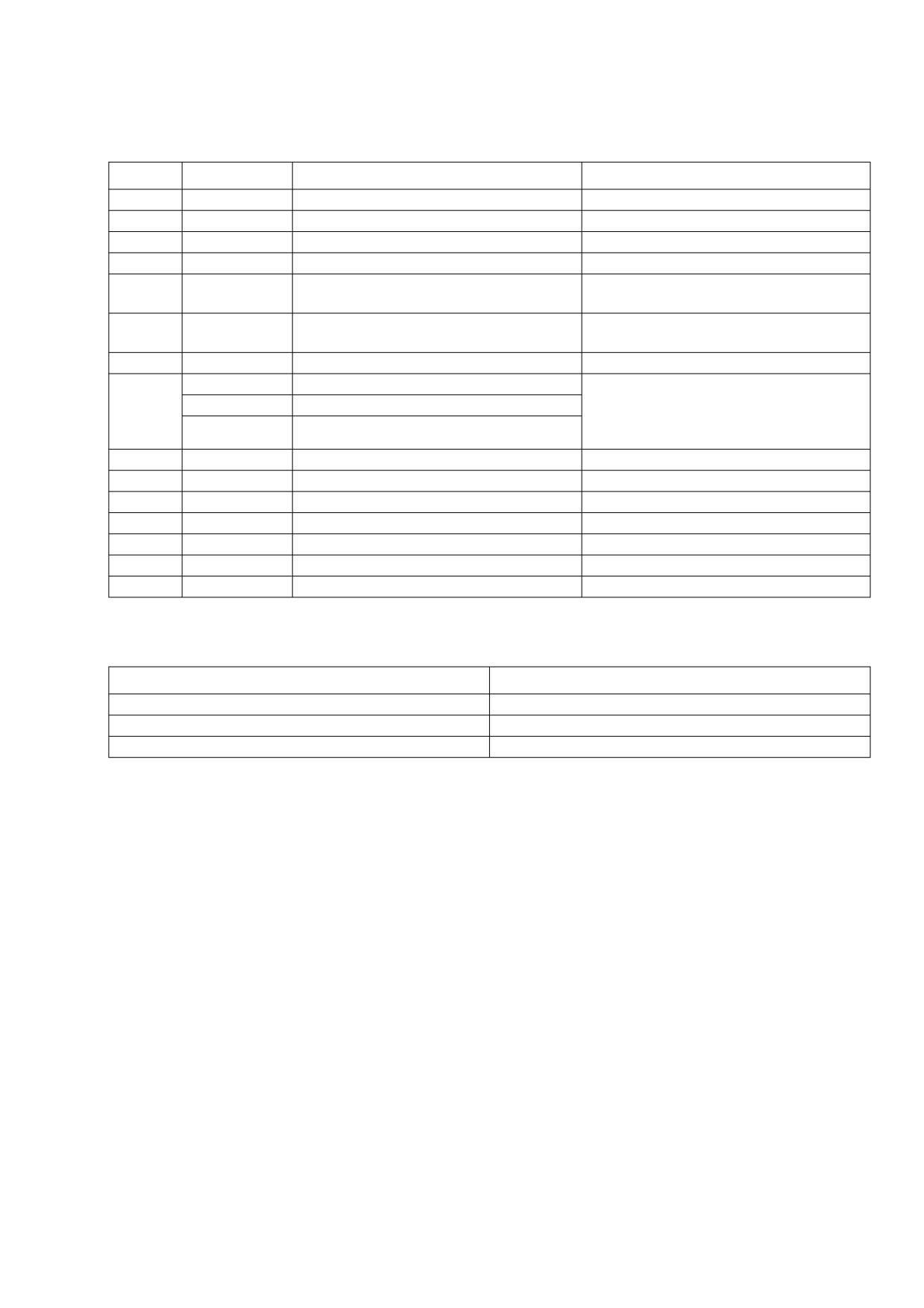
Refer to Table 3-10. This table gives most TSM/TSSM DTC’s
If a particular problem happens to resolve itself, the active
a priority ranking.
status problem is dropped and it becomes a historic DTC
rather than a current DTC. For example, intermittent output
shorts can become typical historic DTC’s.
Historic DTC’s can only be retrieved using a computer based
diagnostic package called DIGITAL TECHNICIAN (Part No.
HD-44750).
Historic DTC’s are stored for 50 ignition cycles after any DTC
was last set as current to assist in the diagnosis of intermit-
tent faults. On the 50th cycle, the DTC will clear itself. The
check engine lamp will not indicate the existence of only his-
toric DTC’s.
It is important to note that historic DTC’s will exist whenever
the system indicates the existence of a current fault. See
MULTIPLE DIAGNOSTIC TROUBLE CODES if multiple
DTC’s are found.
Diagnostic charts are designed for use with current DTC’s
and as a result they frequently suggest part replacement.
When diagnosing a historic DTC the charts can be helpful but
should not lead to part replacement without verification the
part is faulty.
2006 Touring: TSM & TSSM
3-21
HOME
INITIAL DIAGNOSTIC CHECK: TSM/TSSM
3.9
GENERAL
INITIAL DIAGNOSTICS
To locate faulty circuits or other system problems, follow the
diagnostic flow charts in this section. For a systematic
Diagnostic Tips
approach, always begin with INITIAL DIAGNOSTICS which
● If speedometer reads “BUS Er” with the ignition key
follows. Read the general information and then work your way
turned ON (engine stop switch at RUN with the engine
through the flow chart box by box.
off), check data bus for an open or short to ground
between data link connector [91A] terminal 3 and ICM
Diagnostic Notes
connector [10B] terminal 12 (carbureted models), ECM
connector [78B] terminal 5 (EFI models), TSSM connec-
If a numbered circle appears adjacent to a flow chart box,
tor [30B] terminal 3, speedometer connector [39B] termi-
then more information is offered in the diagnostic notes. Many
diagnostic notes contain supplemental information, descrip-
nal
2 or tachometer
(if equipped) connector
[108B]
terminal 2.
tions of various diagnostic tools or references to other parts
of the manual where information on the location and removal
● Check for an open diagnostic test terminal between data
of components may be obtained.
link connector [91A] terminal 3 and TSM/TSSM connec-
tor [30B] terminal 3. With ignition key turned ON, serial
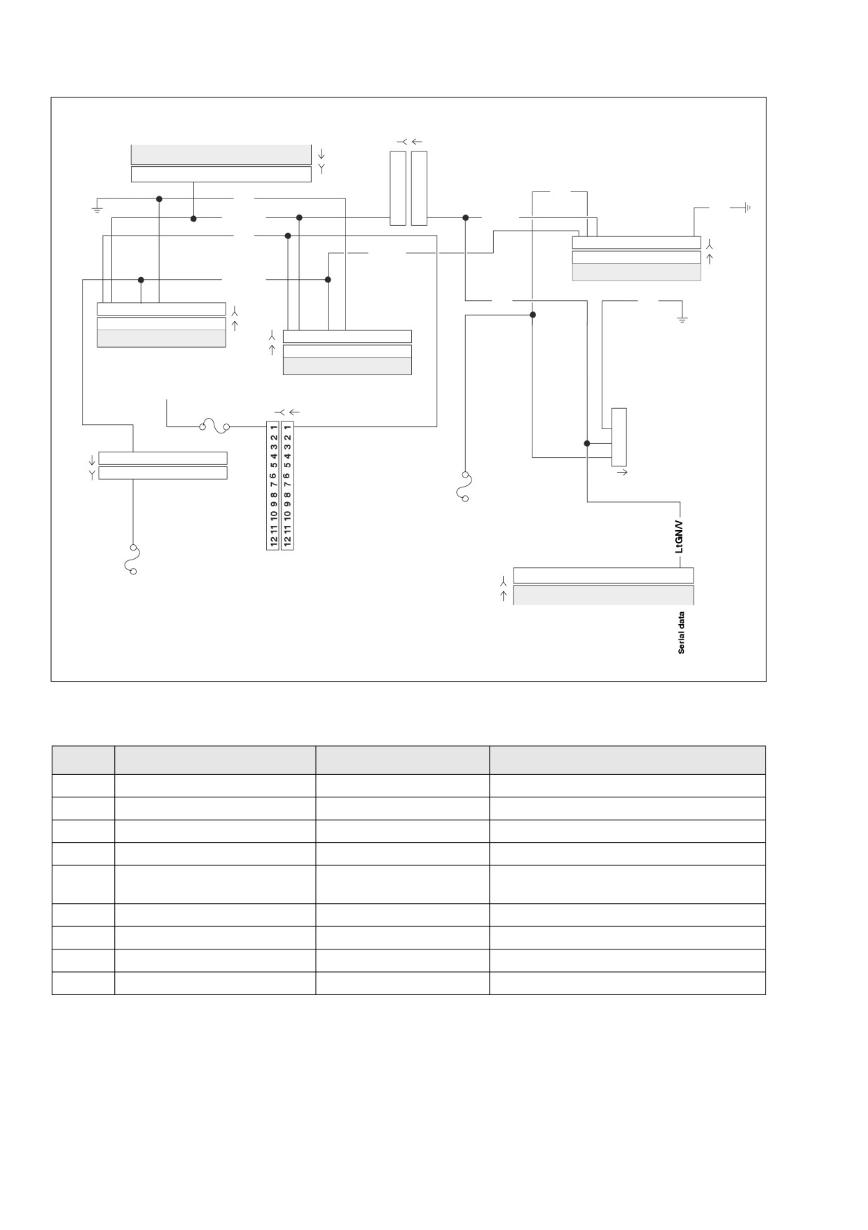
Circuit Diagram/Wire Harness
data bus voltage should be typically 0.6-0.8 volts. The
Connector Table
range of acceptable voltage is 0-7.0 volts.
● To identify intermittents, wiggle instrument and/or vehicle
When working through a flow chart, refer to the illustrations,
harness while performing steps in the Diagnostic Check
the associated circuit diagram and the wire harness connec-
charts.
tor table as necessary. The wire harness connector table for
each circuit diagram identifies the connector number, descrip-
Diagnostic Notes
tion, type and general location.
In order to perform most diagnostic routines, a Breakout Box
The reference numbers below correlate with the circled num-
and a digital volt/ohmmeter (DVOM) are required. See Sec-
bers on the diagnostic check flow charts. See page 3-36.
tion 3.11 BREAKOUT BOX: TSM/TSSM.
1.
Connect BREAKOUT BOX
(Part No. HD-42682)
To perform the circuit checks with any degree of efficiency, a
between wire harness connector [39B] and speedometer
familiarity with the various wire connectors is also necessary.
connector
[39A] using INSTRUMENT HARNESS
ADAPTERS (Part No. HD-46601). See Section
2.5
BREAKOUT BOX: SPEEDOMETER.
Job/Time Code Values
2.
Compare TSM/TSSM system behavior to symptoms in
Some charts may contain warranty job/time codes. Dealer-
Table 3-11.
ship technicians filing warranty claims should use the job/time
code values printed in bold text underneath the appropriate
All TSM/TSSM DTC’s are listed in Table 3-10.
repair.
Other Diagnostic Trouble Codes (DTC’s)
Reprogramming ICM/ECM
See Section 2.5 BREAKOUT BOX: SPEEDOMETER for any
Diagnostic charts frequently suggest ECM/ICM replacement.
DTC’s related to the speedometer.
In the event an ICM or ECM needs to be replaced, it must be
See Section 4.4 INITIAL DIAGNOSTIC CHECK: ICM for any
reprogrammed using a computer based diagnostic package
DTC’s related to the ICM.
called DIGITAL TECHNICIAN (Part No. HD-44750). See your
dealer. Password learn procedure must also be performed.
See Section 5.5 INITIAL DIAGNOSTIC CHECK: EFI for any
See Section 3.24 PASSWORD LEARN.
DTC’s related to the ECM.
3-22
2006 Touring: TSM & TSSM
HOME
Table 3-10. TSM/TSSM Diagnostic Trouble Codes (DTC) and Fault Conditions
PRIORITY
DTC
FAULT CONDITION
SOLUTION
1
“BUS Er”
Serial data bus shorted low/open/high
3.23 DTC U1300, U1301 or “BUS ER”
2
U1300
Serial data low
3.23 DTC U1300, U1301 or “BUS ER”
3
U1301
Serial data high
3.23 DTC U1300, U1301 or “BUS ER”
4
U1016
Loss of ICM/ECM serial data (state of health)
3.21 DTC U1016, U1255
Loss of Speedometer serial data (state of
5
U1097
3.22 DTC U1097, U1255
health)
Missing response from other module
6
U1255
3.22 DTC U1097, U1255
(speedometer) at startup
7
B1135
Accelerometer fault
3.19 DTC B1135
B1151
Sidecar BAS low
Sidecar DTC’s apply only to Touring models
B1152
Sidecar BAS high
equipped with sidecars. If these DTC’s are
8
present on non sidecar equipped motorcycles,
B1153
Sidecar BAS out of range
the TSM/TSSM is not properly configured.
9
B1134
Starter output high
3.18 DTC B1134
10
B1121
Left turn output fault
3.15 TURN SIGNAL ERRORS
11
B1122
Right turn output fault
3.15 TURN SIGNAL ERRORS
12
B0563
Battery voltage high
3.16 DTC B0563
13
B1131
Alarm output low
3.17 DTC B1131, B1132
14
B1132
Alarm output high
3.17 DTC B1131, B1132
15
B1141
Ignition switch open/low
3.15 TURN SIGNAL ERRORS
Table 3-11. Symptoms That May Not Set Diagnostic Trouble Codes
SYMPTOM
SOLUTION
Fob signal to TSSM weak or fails
See 3.14 KEY FOB SIGNAL TO TSSM WEAK OR FAILS
Turn signal will not cancel or cancels erratically
See Turn Signal Error 1A in 3.15 TURN SIGNAL ERRORS
Turn signal flashes double normal rate, all bulbs good
See Turn Signal Error 3A in 3.15 TURN SIGNAL ERRORS
2006 Touring: TSM & TSSM
3-23
HOME
f2353k8b
[156B] [156A]
Main to Interconnect
Radio
[27A]
6
6
Harness
[27B]
5
5
9
4
4
3
3
GY
BK
2
2
BK
LtGN/V
1
1
LtGN/V
O
1
2
3
4 5 6 7 8 9 10 11 12
[30B]
BN/GY
1
2
3
4 5 6 7 8 9 10 11 12
[30A]
TSM/TSSM
BN/GY
[39B]
GY
BK
1
2
3
4 5 6 7 8 9 10 11 12
[39A]
1
2
3
4 5 6 7 8 9 10 11 12
Speedometer
1
2
3
4 5 6 7 8 9 10 11 12
[108B]
1
2
3
4 5 6 7 8 9 10 11 12
To
[108A]
Tachometer
Ignition
Keyswitch
Relay
15A
Instruments
[1B] [1A]
Fuse
1
2
Main to Interconnect
3
[2A]
1
2
3
4 5 6 7 8 9 10 11 12
Harness
4
Data Link
[2B]
1
2
3
4 5 6 7 8 9 10 11 12
[91A]
Main to Interconnect
15A
Harness
Ignition
Fuse
15A
12
Battery
[10B]
Fuse
[10A]
ICM
Figure 3-10. Diagnostic Check: FLHX, FLHT/C (Carbureted)
Table 3-12. Wire Harness Connectors in Figure 3-10.
NO.
DESCRIPTION
TYPE
LOCATION
[1]
Main to Interconnect Harness
12-Place Deutsch (Black)
Inner Fairing - Right Radio Support Bracket
[2]
Main to Interconnect Harness
12-Place Deutsch (Gray)
Inner Fairing - Right Fairing Support Brace
[10]
ICM
12-Place Deutsch
Under Right Side Cover
[27]
Radio
23-Place Amp
Inner Fairing - Back of Radio (Right Side)
Cavity in Crossmember at Rear of
[30]
TSM/TSSM
12-Place Deutsch
Battery Box (Under Seat)
[39]
Speedometer
12-Place Packard
Inner Fairing (Back of Speedometer)
[91]
Data Link
4-Place Deutsch
Under Right Side Cover
[108]
Tachometer
12-Place Packard
Inner Fairing (Back of Tachometer)
[156]
Main to Interconnect Harness
6-Place Deutsch
Inner Fairing - Right Fairing Support Brace
3-24
2006 Touring: TSM & TSSM