Harley Davidson FLHRC 2006. Maintenance & Repair Manual - page 28
HOME
13. Perform the CABLE LASH INITIALIZATION routine des-
f1548x8x
cribed in this section.
CRUISE CONTROL MODULE
REMOVAL
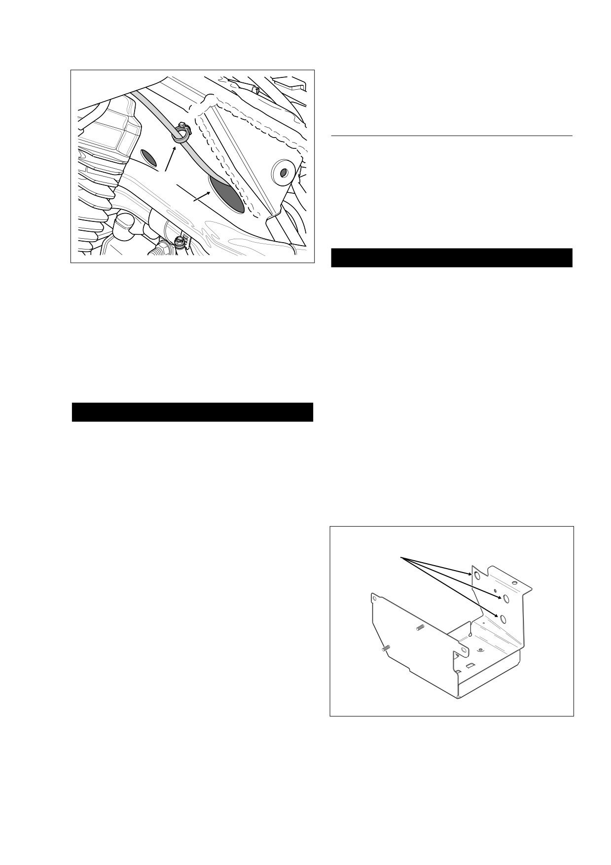
Cable Clip
1.
Remove the air cleaner and backplate. See Section 4.5
AIR CLEANER, REMOVAL.
Hole
2.
Push the plastic end fitting on the cruise cable to the out-
board side to release from wheel pin. See Figure 8-134.
3.
Remove seat. See Section 2.25 SEAT, REMOVAL.
1WARNING
Figure 8-136. Cruise Cable Routing (Left Side)
Always disconnect the negative battery cable first. If the
positive cable should contact ground with the negative
cable installed, the resulting sparks may cause a battery
2.
Slide groove in cruise cable end fitting over cap of wheel
explosion which could result in death or serious injury.
pin. Push on end fitting until it snaps in place. See Figure
8-134.
4.
Unthread bolt and remove battery negative cable (black)
3.
Using slot, slip cruise cable housing into cable guide in
from battery negative (-) terminal.
throttle cable bracket. At bottom of bracket, install new
5.
Unthread bolt and remove battery positive cable (red)
E-clip on sleeve at end of cruise cable housing.
from battery positive (+) terminal.
4.
Feed cruise cable and connector through hole in frame
6.
Loosen T40 TORX screw and move lip of hold-down
crossmember. See Figure 8-136.
clamp off edge of battery. Remove battery from battery
box.
CAUTION
7.
Lift locking latch and remove cruise module connector
Be sure that the ribbon is not twisted. A twisted ribbon
[17], 10-place Packard. See Figure 8-133.
may adversely affect performance or even prevent cruise
8.
Rotate cruise cable connector in a counterclockwise
operation.
direction to detach from cruise module.
5.
With the hole in the ribbon end eyelet and the flat on the
9.
From inside battery box, remove three flange bolts.
cable connector housing facing outboard, fit cable end
Carefully pull cruise module away from side of battery
bead into ribbon end eyelet. See Figure 8-135.
box exercising caution to avoid losing grommets.
6.
Verify that bead, eyelet and ribbon are lined up correctly.
If necessary, remove plastic end fitting from wheel pin
and gently pull on end fitting to remove cable slack.
Reinstall end fitting, if removed.
f2004x8x
Mounting
7.
Insert cruise cable connector into cruise module and
Holes
rotate in a clockwise direction until tabs on connector
fully engage grooves or detentes in cruise module hous-
ing.
8.
Capture cruise cable in cable clip and anchor in hole of
frame crossmember. See Figure 8-136.
9.
Adjust the throttle and idle cables. See CABLE ADJUST-
MENT, in this section.
10. Install backplate and air cleaner assembly. See Section
4.5 AIR CLEANER, INSTALLATION.
11. Align barbed studs in side cover with grommets in frame
downtubes and push firmly into place
(no tools
required).
12. Install left side saddlebag. See Section 2.26 SADDLE-
BAG, INSTALLATION.
Figure 8-137. Battery Box (Right Side View)
2006 Touring: Electrical
8-107
HOME
INSTALLATION
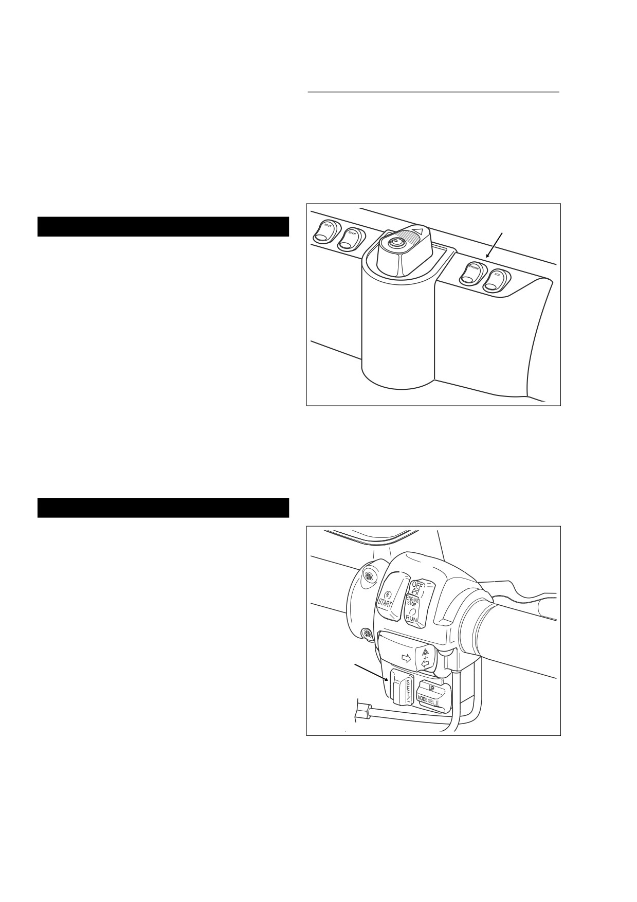
CRUISE CONTROL SWITCHES
1.
Install grommets into holes on left side of battery box
with the larger OD on the outboard side. See Figure 8-
FAIRING CAP
137.
2.
Align threaded holes on inboard side of cruise module
See Figure 8-138. For instructions on replacement of the
with holes in grommets and install flange bolts from
CRUISE ON/OFF SWITCH, see Section 8.20 FAIRING
inside battery box.
CAP SWITCHES (FLHTC/U), Section 8.21 INSTRU-
MENT NACELLE SWITCHES (FLTR), or Section 8.22
3.
Alternately tighten flange bolts to 60-96 in-lbs (6.8-10.9
HANDLEBAR SWITCHES (FLHRC).
Nm). Install cruise module connector [17] and engage
locking latch.
Cruise ON/OFF
CAUTION
Switch
Be sure that the ribbon is not twisted. A twisted ribbon
may adversely affect performance or even prevent cruise
operation.
4.
With the hole in the ribbon end eyelet and the
flat on the
cable connector housing facing outboard, fit
cable end
bead into ribbon end eyelet. See Figure 8-135.
5.
Verify that bead, eyelet and ribbon are lined up correctly.
If necessary, remove plastic end fitting from wheel pin
and gently pull on end fitting to remove cable slack.
6.
Insert cruise cable connector into cruise module and
rotate in a clockwise direction until tabs on connector
fully engage grooves or detentes in cruise module hous-
f2031x8x
ing.
Figure 8-138. Fairing Cap (FLHTCU)
7.
Install cruise module connector [17], 10-place Packard.
See Figure 8-133.
8.
Place battery in battery box, terminal side forward.
HANDLEBAR
Rotate the hold-down clamp so that the lip (with rubber
pad) rests on the edge of the battery. Tighten T40 TORX
See Figure 8-139. For instructions on replacement of the
screw to 15-20 ft-lbs (20-27 Nm).
handlebar mounted CRUISE SET/RESUME switch, see
Section
8.22 HANDLEBAR SWITCHES, SWITCH
REPAIR/REPLACEMENT.
1WARNING
Always connect the positive battery cable first. If the
f1368a8x
positive cable should contact ground with the negative
cable installed, the resulting sparks may cause a battery
explosion which could result in death or serious injury.
9.
Insert bolt through battery positive cable
(red) into
threaded hole of battery positive (+) terminal. Tighten
bolt to 60-96 in-lbs (6.8-10.9 Nm).
10. Insert bolt through battery negative cable (black) into
threaded hole of battery negative (-) terminal. Tighten
bolt to 60-96 in-lbs (6.8-10.9 Nm).
Set/Resume
11. Install seat. See Section 2.25 SEAT, INSTALLATION.
Switch
12. Slide groove in cruise cable end fitting over cap of wheel
pin. Push on end fitting until it snaps in place. See Figure
8-134.
13. Install backplate and air cleaner assembly. See Section
4.5 AIR CLEANER, INSTALLATION.
14. Perform the CABLE LASH INITIALIZATION routine des-
Figure 8-139. Right Handlebar Switch Assembly
cribed in this section.
(FLTR, FLHTCU)
8-108
2006 Touring: Electrical
HOME
ADVANCED AUDIO SYSTEM (FLHX, FLHTC/U, FLTR)
8.32
RADIO (STORAGE BOX)
REMOVAL
1.
Remove maxi-fuse. See Section 8.3 SYSTEM FUSES,
MAXI-FUSE, REMOVAL.
2.
Remove outer fairing. Proceed as follows:
FLHX, FLHT/C/U: See Section 2.30 UPPER FAIRING/
WINDSHIELD (FLHX, FLHT/C/U), OUTER FAIRING/
WINDSHIELD, REMOVAL.
FLTR: See Section
2.31 UPPER FAIRING/WIND-
SHIELD (FLTR), OUTER FAIRING, REMOVAL.
3.
On FLHTCU models, remove the CB module. See CB
MODULE, REMOVAL, steps 3-4, in this section.
f1559x8x
4.
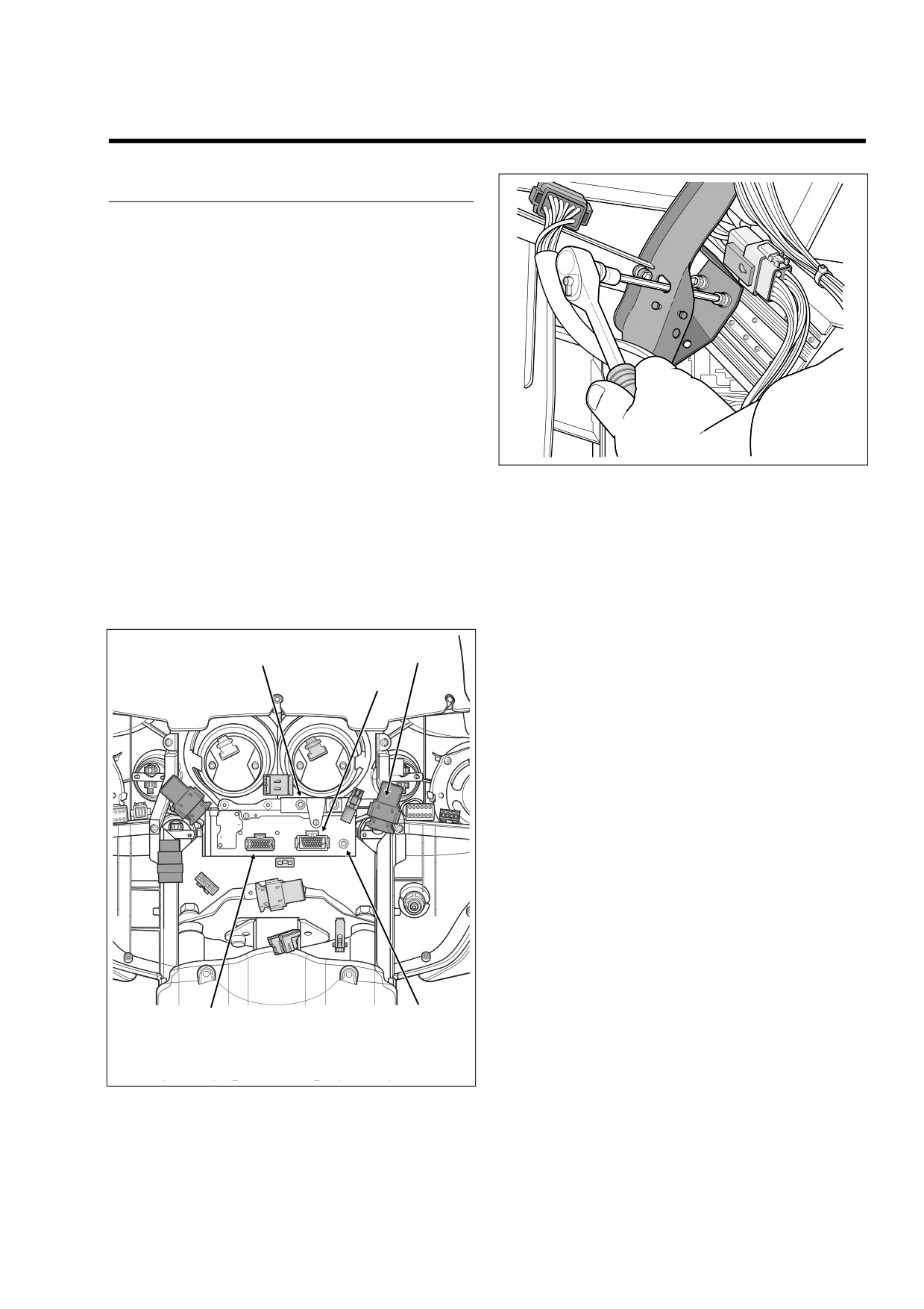
See Figure 8-140. Disconnect the following connectors:
Figure 8-141. Release Radio from Fairing Brackets
FLHX, FLHTC/U, FLTR:
(FLHTC/U)
● Radio connector [27], 23-place Amp.
● Radio antenna cable connector [51].
5.
Using a long shank ball end socket (Snap-on® FABL6E),
remove four socket head screws to release radio (stor-
FLHTCU Only:
age box on FLHT) from left and right radio support
● Radio connector [28], 35-place Amp.
brackets. Use oblong holes in fairing brackets to access
screws. See Figure 8-141.
6.
Pull radio (storage box on FLHT) forward to remove from
f2356x8x
opening in inner fairing.
[50]
[184]
[28]
INSTALLATION
1.
Position radio (storage box on FLHT) between radio sup-
port brackets and push into opening in inner fairing.
2.
Align threaded inserts in sides of radio (storage box on
FLHT) with holes in left and right radio support brackets.
Starting at the rear, install four socket head screws.
Alternately tighten screws to 35-45 in-lbs (4.0-5.1 Nm).
Use oblong holes in fairing brackets to access screws.
3.
See Figure 8-140. Connect the following connectors:
FLHX, FLHTC/U, FLTR:
● Radio connector [27], 23-place Amp.
● Radio antenna cable connector [51].
FLHTCU Only:
● Radio connector [28], 35-place Amp.
4.
On FLHTCU models, install the CB module. See CB
[27]
[51]
MODULE, INSTALLATION, steps 1-3, in this section.
[27] Radio
5.
Install outer fairing. Proceed as follows:
[28] Radio
[51] Radio Antenna Cable
[50] CB Antenna Cable
[184] CB Module
FLHX, FLHT/C/U: See Section 2.30 UPPER FAIRING/
WINDSHIELD (FLHX, FLHT/C/U), OUTER FAIRING/
Figure 8-140.
Radio Connections (FLHTC/U)
WINDSHIELD, INSTALLATION.
2006 Touring: Electrical
8-109
HOME
FLTR: See Section
2.31 UPPER FAIRING/WIND-
SHIELD (FLTR), OUTER FAIRING, INSTALLATION.
1.
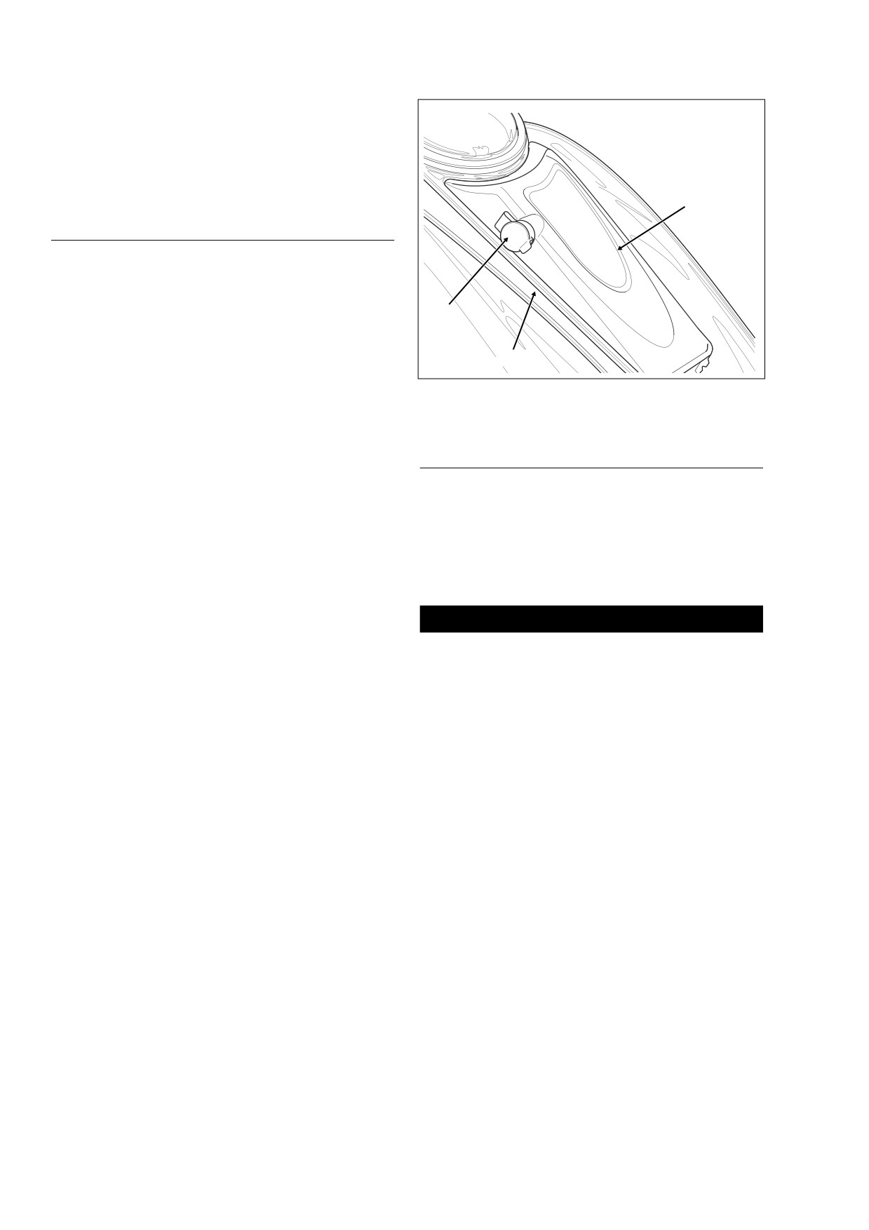
Console
2.
Pod
6.
Install maxi-fuse. See Section
8.3 SYSTEM FUSES,
3.
Headset Receptacle
MAXI-FUSE, INSTALLATION.
Cap
2
FRONT FAIRING SPEAKERS
REMOVAL
1.
Remove outer fairing. Proceed as follows:
3
FLHX, FLHTC/U: See Section 2.30 UPPER FAIRING/
WINDSHIELD (FLHX, FLHT/C/U), OUTER FAIRING/
WINDSHIELD, REMOVAL.
f2019x8x
1
FLTR: See Section
2.31 UPPER FAIRING/WIND-
Figure 8-142. Console Pod Assembly
SHIELD (FLTR), OUTER FAIRING, REMOVAL.
2.
Carefully pull the socket terminals from the speaker
spade contacts.
CONSOLE POD ASSEMBLY
3.
Remove three T25 TORX screws to release the speaker
adapter assembly from the inner fairing.
NOTE
4.
Carefully pull speaker from adapter.
The following instructions may also be used for replacement
of the chrome fuel tank console on which the pod is mounted.
INSTALLATION
REMOVAL
1.
With the speaker spade contacts at the top of the
1.
Remove seat. See Section 2.25 SEAT, REMOVAL.
adapter, the top being the side with the widest edge,
snap speaker into adapter using finger pressure.
1
WARNING
2.
If speaker grille is loose, apply 3M-847 adhesive (HD
Part No. 99618-60) to outer edge of adapter ring. Install
To protect against shock and accidental start-up of vehi-
grille on adhesive.
cle, disconnect the negative battery cable before pro-
ceeding. Inadequate safety precautions could result in
3.
With the widest edge of adapter at the top, align holes in
death or serious injury.
speaker adapter assembly with those in inner fairing.
2.
Unthread bolt and remove battery negative cable (black)
4.
Install two long screws to secure top of speaker adapter
from battery negative (-) terminal.
assembly to inner fairing. Capturing fairing support
brace, install short screw in lower outboard hole (posi-
3.
Remove left side saddlebag. See Section 2.26 SAD-
tioning flat washer between adapter and support brace).
DLEBAG, REMOVAL.
The screw hole on the lower inboard side is not used.
4.
Gently pull side cover from frame downtubes (no tools
5.
Using a T25 TORX drive head, tighten the lower speaker
required).
screw to 22-28 in-lbs (2.5-3.2 Nm). Tighten the two
5.
Carefully cut cable strap securing console pod conduit
upper speaker screws to 35-50 in-lbs (4.0-5.7 Nm).
and audio harness to left frame tube at front and rear of
saddlebag rail.
6.
Install the socket terminals onto the speaker spade con-
tacts. Different size spade contacts prevent improper
6.
Open fuel door on console. Remove two Allen head
assembly.
screws inboard of rubber bumpers. These screws secure
console to clip nuts on the canopy bracket.
7.
Install outer fairing. Proceed as follows:
7.
Remove Allen head screw to detach flange at rear of
FLHX, FLHTC/U: See Section 2.30 UPPER FAIRING/
console from clip nut on fuel tank weldment.
WINDSHIELD (FLHX, FLHT/C/U), OUTER FAIRING/
WINDSHIELD, INSTALLATION.
8.
Lay a clean shop towel on forward part of the rear
fender. Remove filler cap from neck of fuel tank. Remove
FLTR: See Section
2.31 UPPER FAIRING/WIND-
console and lay upside down on shop towel. Reinstall
SHIELD (FLTR), OUTER FAIRING, INSTALLATION.
filler cap.
8-110
2006 Touring: Electrical
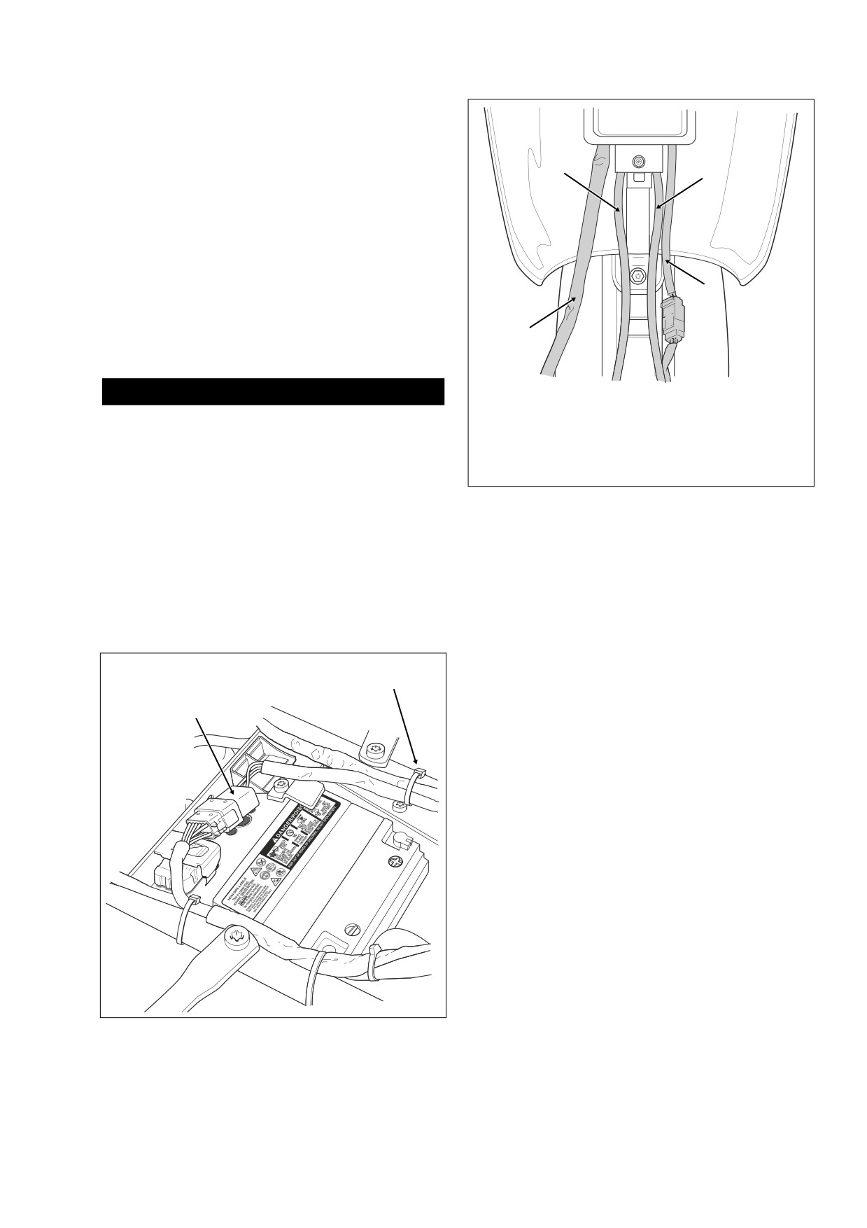
HOME
9.
Bend back flexible clamp to release pod cable conduit
from bottom of console.
f2007x9x
10. Release console pod connector [53], 12-place Deutsch,
from attachment clip anchored in hole of frame cross-
member (at rear of battery box). See Figure 8-143. Dis-
1
2
connect pin and socket halves.
11. Remove three Phillips screws to release pod from con-
sole.
INSTALLATION
1.
Feed pin housing and conduit through top of console
3
seating pod in recess. Install three Phillips screws
screws to secure pod to console. Alternately tighten
4
screws to 6-11 in-lbs (0.7-1.2 Nm). Capture conduit in
flexible clamp at bottom of console.
1WARNING
1.
Fuel Vapor Vent Tube (To Vapor Valve)
Exercise caution to avoid pinching or kinking the fuel
2.
Fuel Overflow Hose
overflow hose when console is installed. A blocked hose
3.
Fuel Tank Harness
can cause excess gasoline to remain above the filler
(To Fuel Pump/Fuel Level Sender)
neck insert, while fuel expansion can cause an overfilled
4.
Console Pod Conduit
tank to overflow through the filler cap vent. Gasoline is
extremely flammable and highly explosive. Inadequate
Figure 8-144. Console Pod Cable/Hose Routing
safety precautions could result in death or serious
(FLHTCU)
injury.
2.
Remove filler cap. Place console over filler neck onto
canopy. Route cables from beneath console as shown in
3.
Install Allen head screw to fasten rear flange of console
Figure 8-144. Be sure that hoses and wires are not
to clip nut on fuel tank weldment. Tighten screw to 25-30
pinched by the console during installation. Reinstall filler
in-lbs (2.8-3.4 Nm).
cap.
4.
Open fuel door on console. Install two Allen head screws
to secure front of console to clip nuts on canopy bracket.
Alternately tighten screws to 25-30 in-lbs (2.8-3.4 Nm).
Cable Strap
Console Pod
Connector [53]
5.
Install new cable straps to secure console pod conduit
and audio harness to left frame tube at front and rear of
saddlebag rail. Cut any excess cable strap material. See
Figure 8-143.
6.
Connect console pod connector [53], 12-place Deutsch.
Install connector onto attachment clip anchored in hole
of frame crossmember (at rear of battery box).
7.
Insert bolt through battery negative cable (black) into
threaded hole of battery negative (-) terminal. Tighten
bolt to 60-96 in-lbs (6.8-10.9 Nm).
8.
Install seat. See Section 2.25 SEAT, INSTALLATION.
9.
Align barbed studs in side cover with grommets in frame
downtubes and push firmly into place
(no tools
required).
10.
Install left side saddlebag. See Section 2.26 SADDLE-
f2192x8x
BAG, INSTALLATION.
Figure 8-143. Disconnect Console Pod Connector
2006 Touring: Electrical
8-111
HOME
FRONT HEADSET RECEPTACLE
Table 8-18. Front Headset Receptacle
Chamber
Wire Color
REMOVAL
Number
Blue/Yellow
6
1.
Remove console pod. See CONSOLE POD ASSEM-
BLY, REMOVAL, in this section.
Yellow/Black
7
2.
Remove terminals 6 through 12 from pin housing of 12-
Yellow/White
8
place Deutsch connector.
Yellow/Red
9
NOTE
Black
10
For instructions on properly removing wire terminals, see
Red
11
APPENDIX B.1 DEUTSCH ELECTRICAL CONNECTORS,
Black (Thick Insulation)
12
REMOVING/INSTALLING PINS.
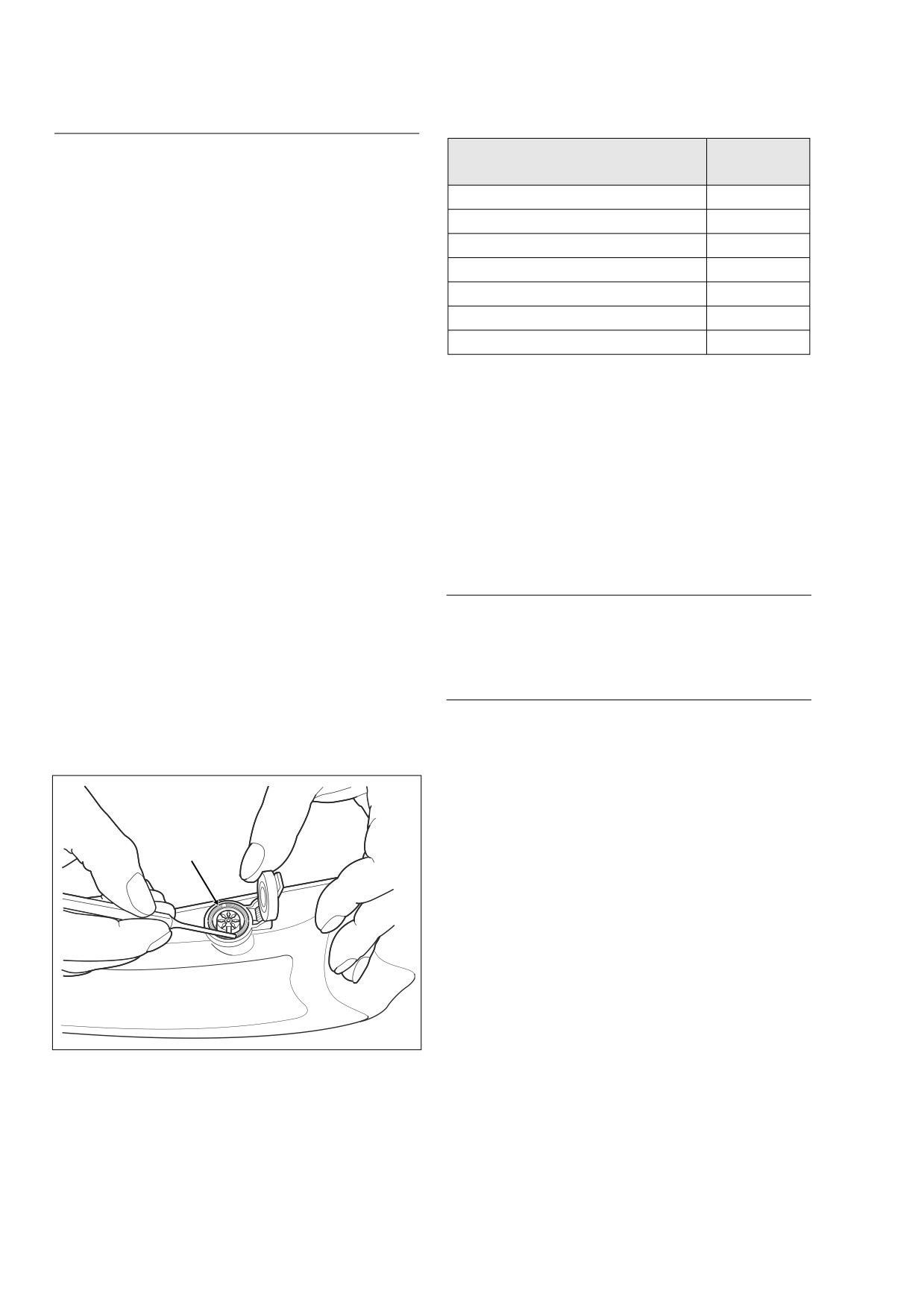
3.
Raise headset receptacle cap. Place pin punch in either
NOTE
notch of lock ring and rotate in a counterclockwise direc-
For instructions on properly installing wire terminals, see
tion until loose. See Figure 8-145.
APPENDIX B.1 DEUTSCH ELECTRICAL CONNECTORS,
4.
Remove lock ring and cap from headset receptacle.
REMOVING/INSTALLING PINS.
5.
Remove headset receptacle from pod.
6.
Install console pod. See CONSOLE POD ASSEMBLY,
INSTALLATION, in this section.
INSTALLATION
7.
Test operation of headset receptacle.
1.
From inside pod, insert threaded end of headset recep-
tacle through side hole.
REAR HEADSET RECEPTACLE
2.
Place receptacle cap over end of headset receptacle so
that it seats in recess of pod.
See Section 8.37 AUDIO HARNESS (FLHTCU).
3.
Open cap, and with the notches on the outboard side,
thread lock ring onto headset receptacle.
4.
Place pin punch in either notch of lock ring and rotate in
REAR PASSENGER SWITCHES
a clockwise direction until tight.
5.
Install terminals 6 through 12 into pin housing of 12-
place Deutsch connector.
REMOVAL
NOTE
Right and left side replacement passenger switch assem-
blies are interchangeable.
1.
Remove maxi-fuse. See Section 8.3 SYSTEM FUSES,
MAXI-FUSE, REMOVAL.
Lock Ring
2.
Open Tour-Pak.
3.
Remove four T10 TORX screws and pull speaker grille
from speaker box.
4.
Remove speaker from speaker box and carefully pull
socket terminals from speaker spade contacts.
5.
Remove trim ring and gently pull on wire harness to
draw rear speaker/passenger controls connector,
6-
place Deutsch, out of speaker box.
f2020x8x
6.
Disconnect pin and socket halves of Deutsch connector.
Figure 8-145. Remove Lock Ring from Receptacle
7.
Draw socket half of Deutsch connector back into
Using Pin Punch
speaker box and pull out through speaker hole.
8-112
2006 Touring: Electrical
HOME
NOTE
For instructions on properly installing wire terminals, see
APPENDIX B.1 DEUTSCH ELECTRICAL CONNECTORS,
REMOVING/INSTALLING SOCKETS.
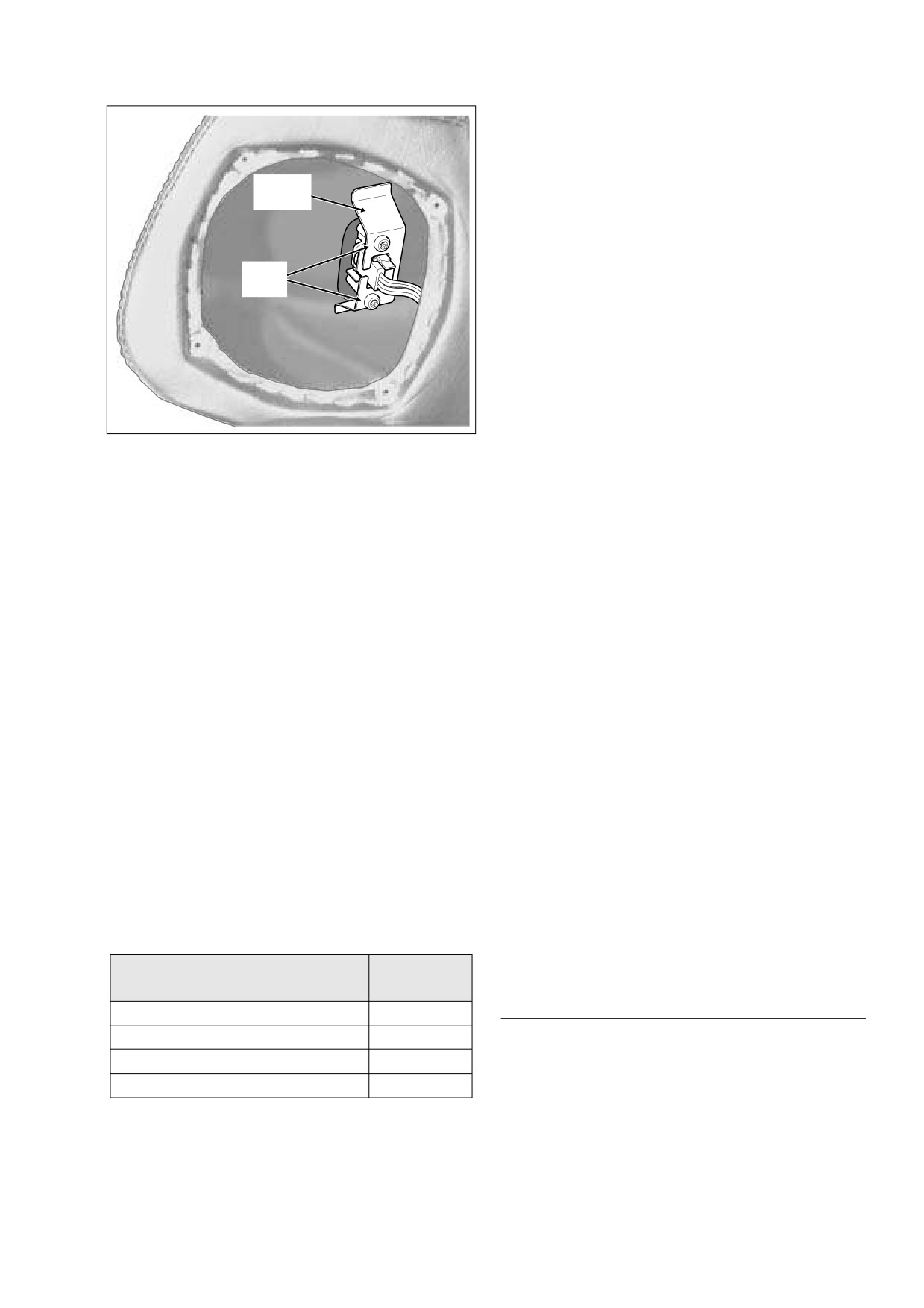
Switch
3.
With the Pink/White wire at the bottom, place switch in
Bracket
cavity of switch housing. Bottom of the assembly is
determined by location of rib on switch housing. See Fig-
ure 8-147.
4.
Note lettering for proper orientation and gently push key-
TORX
cap onto switch shaft. When orienting keycap, remember
Screw
that bottom of assembly is determined by location of
switch housing rib.
5.
Feed Deutsch socket connector, speaker terminals and
conduit through switch housing hole on outboard side of
speaker box until switch housing backplate contacts
speaker box. Pull harness out through speaker hole.
f1492b8x
NOTE
To align bracket and switch housing holes, slot in bracket
Figure 8-146. Remove Passenger Switch Assembly
must face toward the front on right side assembly and toward
(Right Side Speaker Box Shown)
the rear on left side. See Figure 8-148. Switch also must be
square in cavity of switch housing or bracket will not fit.
8.
Remove two T25 TORX screws to release switch bracket
6.
Reaching into speaker box, align holes in bracket with
from inside of speaker box. Remove bracket using slot to
holes in switch housing. Install two T25 TORX screws.
free switch wires. See Figure 8-146.
See Figure 8-149.
9.
Pull switch housing assembly, wire harness conduit,
7.
Feed Deutsch socket through speaker hole into speaker
speaker terminals and Deutsch socket from speaker box
box and pull out through harness hole on inboard side.
using switch housing hole on outboard side.
8.
Mate pin and socket halves of Deutsch connector. Feed
10. Carefully pull keycap from switch shaft. Remove switch
connector back up into speaker box pressing trim ring
from switch housing.
into hole.
11. Remove terminals 1 through 4 from socket housing.
9.
Install socket terminals onto speaker spade contacts. On
right side of vehicle, install socket terminal of the solid
NOTE
Green wire onto contact next to the red dot. On left side,
For instructions on properly removing wire terminals, see
install socket terminal of the solid Brown wire onto con-
APPENDIX B.1 DEUTSCH ELECTRICAL CONNECTORS,
tact next to the red dot.
REMOVING/INSTALLING SOCKETS.
10. Align holes in speaker grille with those in speaker and
12. Pulling one wire at a time, remove four wires from con-
slide four TORX screws through grille and speaker
duit.
holes.
11. With spade contacts at bottom rear corner, position
speaker/grille assembly against speaker box. Install four
INSTALLATION
T10 TORX screws and alternately tighten in a crosswise
1.
Pushing one wire at a time, feed four wires of new switch
pattern.
through conduit.
12. Close Tour-Pak.
2.
Install terminals 1 through 4 into socket housing.
13. Install maxi-fuse. See Section
8.3 SYSTEM FUSES,
MAXI-FUSE, INSTALLATION.
Table 8-19. Rear Passenger Switches
14. Test switch for proper operation.
Chamber
Wire Color
Number
REAR SPEAKERS
Pink/White
1
Gray/White
2
REMOVAL
Violet/Black
3
* Orange/Black
4
1.
Remove maxi-fuse. See Section 8.3 SYSTEM FUSES,
MAXI-FUSE, REMOVAL.
* Mates to O/BK on [41A], BN/W on [42A].
2006 Touring: Electrical
8-113
HOME
f1494b8x
f1491x8x
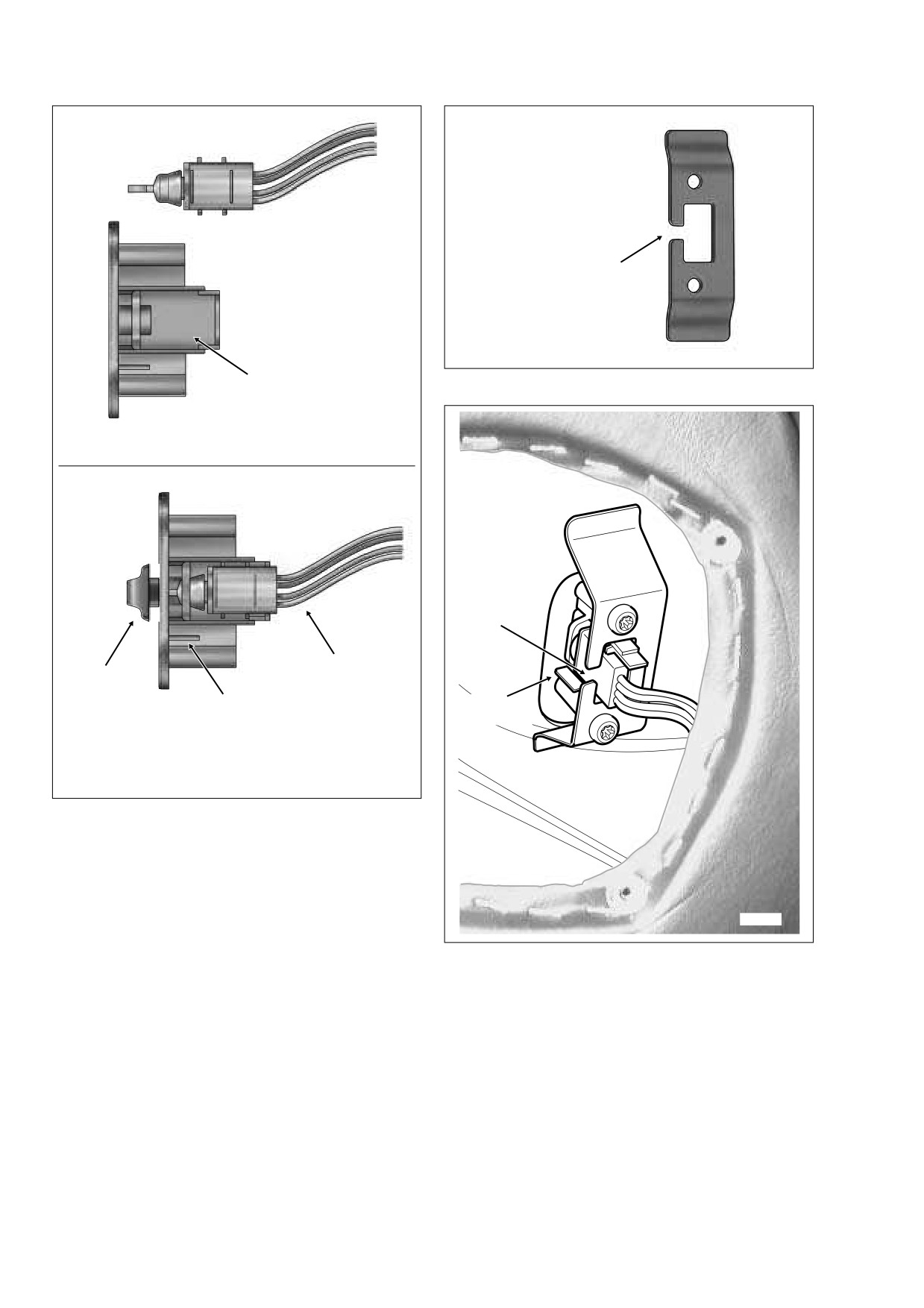
1
Front on right side,
rear on left side.
3
Figure 8-148. Properly Orient Slot in Switch Bracket
2
DISASSEMBLED
f1495x8x
ASSEMBLED
Slot
Forward
4
6
Rib
5
Bottom
1.
Passenger Switch
4.
Pink/White Wire
2.
Switch Housing
5.
Rib
3.
Cavity
6.
Keycap
Figure 8-147. Install Switch in Housing
2.
Open Tour-Pak.
3.
Remove four T10 TORX screws from speaker grille.
Remove speaker grille from speaker box.
f1492x8x
4.
Remove speaker from speaker box. Carefully pull two
Figure 8-149. Install Passenger Switch Assembly
socket terminals from speaker spade contacts.
(Right Side Speaker Box Shown)
INSTALLATION
2.
With spade contacts at bottom, install speaker in
speaker box.
1.
Install two socket terminals onto speaker spade con-
tacts. Different size spade contacts prevent improper
3.
Align holes in speaker with those in speaker box. Align
assembly.
holes in grille with those in speaker.
8-114
2006 Touring: Electrical
HOME
4.
Install four T10 TORX screws and alternately tighten in a
2.
Open Tour-Pak. Open map pocket and remove acorn
crosswise pattern.
nuts. Remove map pocket and molded liner from Tour-
Pak.
5.
Close Tour-Pak.
6.
Install maxi-fuse. See Section
8.3 SYSTEM FUSES,
3.
Disconnect CB antenna cable connector [50] on right
MAXI-FUSE, INSTALLATION.
side of Tour-Pak. Release cable from rear adhesive clip
at bottom of Tour-Pak.
7.
Test speaker for proper operation.
4.
Remove Keps nut, ring terminal and flat washer from
loading coil stud.
CB MODULE
5.
Holding hex head screw, remove flange nut at bottom of
Tour-Pak to release loading coil bracket. Remove hex
head screw (with external tooth lockwasher) and loading
REMOVAL
coil from motorcycle.
1.
Remove maxi-fuse. See Section 8.3 SYSTEM FUSES,
MAXI-FUSE, REMOVAL.
INSTALLATION
2.
Remove outer fairing. See Section 2.30 UPPER FAIR-
ING/WINDSHIELD (FLHX, FLHT/C/U), OUTER FAIR-
1.
Place new loading coil into position aligning hole in
ING/WINDSHIELD, REMOVAL.
bracket with hole in rear right corner of Tour-Pak. Slide
hex head screw (with external tooth lockwasher) through
3.
See Figure 8-140. Disconnect the following connectors:
holes. At bottom of Tour-Pak, install flange nut on hex
● CB antenna cable connector [50]. Rotate knurled
head screw.
nut counterclockwise until free.
2.
Connect CB antenna cable connector
[50]. Capture
● CB module connector
[184],
12-place Deutsch
antenna cable in rear adhesive clip at bottom of Tour-
(black); top of radio (left side).
Pak.
4.
Remove screw to release flange of CB module from
3.
Install flat washer, ring terminal and Keps nut onto load-
radio.
ing coil stud. Tighten Keps nut.
4.
Install molded liner in Tour-Pak. Install map pocket and
INSTALLATION
secure using acorn nuts. Close Tour-Pak.
1.
Fit metal cones on CB module into rubber grommets at
5.
Install maxi-fuse. See Section
8.3 SYSTEM FUSES,
top of radio. Use the position above radio connector [28],
MAXI-FUSE, INSTALLATION.
35-place Amp, as the other location has been reserved
6.
Check SWR and adjust if necessary. Follow the SWR
for certain P&A accessories.
Adjustment procedure in Section 6 of the 2006 ELEC-
2.
Install screw to fasten flange of CB module to radio.
TRICAL DIAGNOSTIC MANUAL (Part No. 99497-06).
Tighten screw to 35-45 in-lbs (4.0-5.1 Nm).
Remove SWR meter, install antenna connector and
tighten antenna connector stud.
3.
See Figure 8-140. Connect the following connectors:
● CB antenna cable connector [50]. Insert pin and
rotate knurled nut clockwise until tight.
● CB module connector
[184],
12-place Deutsch
AUDIO HARNESS
(black); top of radio (left side).
For removal and installation instructions, see Section 8.37
4.
Install outer fairing. See Section 2.30 UPPER FAIRING/
AUDIO HARNESS (FLHTCU).
WINDSHIELD (FLHX, FLHT/C/U), OUTER FAIRING/
WINDSHIELD, INSTALLATION.
5.
Install maxi-fuse. See Section
8.3 SYSTEM FUSES,
RADIO ANTENNA CABLE
MAXI-FUSE, INSTALLATION.
For removal and installation, see Section
8.36 RADIO
ANTENNA CABLE.
CB LOADING COIL
CB ANTENNA CABLE
REMOVAL
1.
Remove maxi-fuse. See Section 8.3 SYSTEM FUSES,
For removal and installation, see Section 8.38 CB ANTENNA
MAXI-FUSE, REMOVAL.
CABLE (FLHTCU).
2006 Touring: Electrical
8-115
HOME
WIRE TROUGH
8.33
REMOVAL
9306
1.
Remove fuel tank. For carbureted models, see Section
4.7 FUEL TANK
(CARBURETED), COMPLETE
REMOVAL, FLHX, FLHT or FLHR/S. For fuel injected
models, see Section
9.4 FUEL TANK
(FUEL
INJECTED), COMPLETE REMOVAL, FLHXI, FLHT/C/
U/I, FLTRI or FLHR/C/S/I.
2.
Unthread bolt and remove battery positive cable (red)
from battery positive
(+) terminal.
(Battery negative
cable already removed under FUEL TANK, COMPLETE
REMOVAL.)
3.
Loosen T40 TORX screw and move lip of hold-down
clamp off edge of battery. Remove battery from battery
box.
Figure 8-150. Release Catches From Cover
4.
Starting at the front of the wire trough, and working
rearward from side to side, release catches to remove
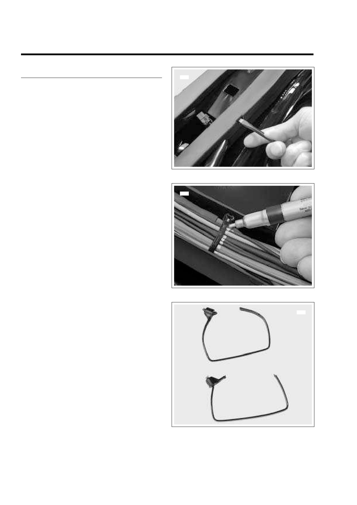
9294
cover. For most catches, carefully insert blade of flat tip
screwdriver into slot only as far as necessary to release
catch. See Figure 8-150.
5.
Using a paint pen, draw a line on the conduit and/or wire
bundle on both sides of each cable strap. See Figure 8-
151.
NOTE
If multiple branches of the harness are bound by a single
cable strap, such as the breakouts leading to the induction
module on fuel injected models, be sure to mark all branches
with the paint pen.
6.
Starting at the front of the wire trough, cut the first cable
strap as close to the eyelet as possible. Be sure to cut off
Figure 8-151. Mark Location of Cable Straps
the tail of the cable strap and not the eyelet. The cable
strap can be reused for use in step 7 if only the tail is
9298
removed, but it must be replaced with a new cable strap
if the eyelet is cut off. See Figure 8-152.
7.
Remove the tail remnant from the eyelet of the cable
REUSABLE
strap, if present. Remove the cable strap from the slots
(tail removed)
in the wire trough and install it back on the harness just
outside the painted lines. Be sure to capture each wire
of the harness, but not the wire trough. Repeat steps 6-7
for all remaining cable straps.
NOTE
If multiple branches of the harness are bound by a single
cable strap, such as the breakouts leading to the induction
module on fuel injected models, install new cable strap just
NOT REUSABLE
(eyelet removed)
outside the painted lines before cutting original cable strap
through wire trough. This will further ensure that stackup and
breakout lengths remain the same.
Figure 8-152. Cut Cable Straps
8-116
2006 Touring: Electrical
HOME
8.
Gently pull index pins on rear legs of wire trough from
holes in frame backbone. For best results, work both
pins loose at the same time.
9.
Slide wire trough forward to release slot at bottom from
T-stud a center of frame backbone.
10. Raise wire harness and carefully remove wire trough
from left side of motorcycle.
INSTALLATION
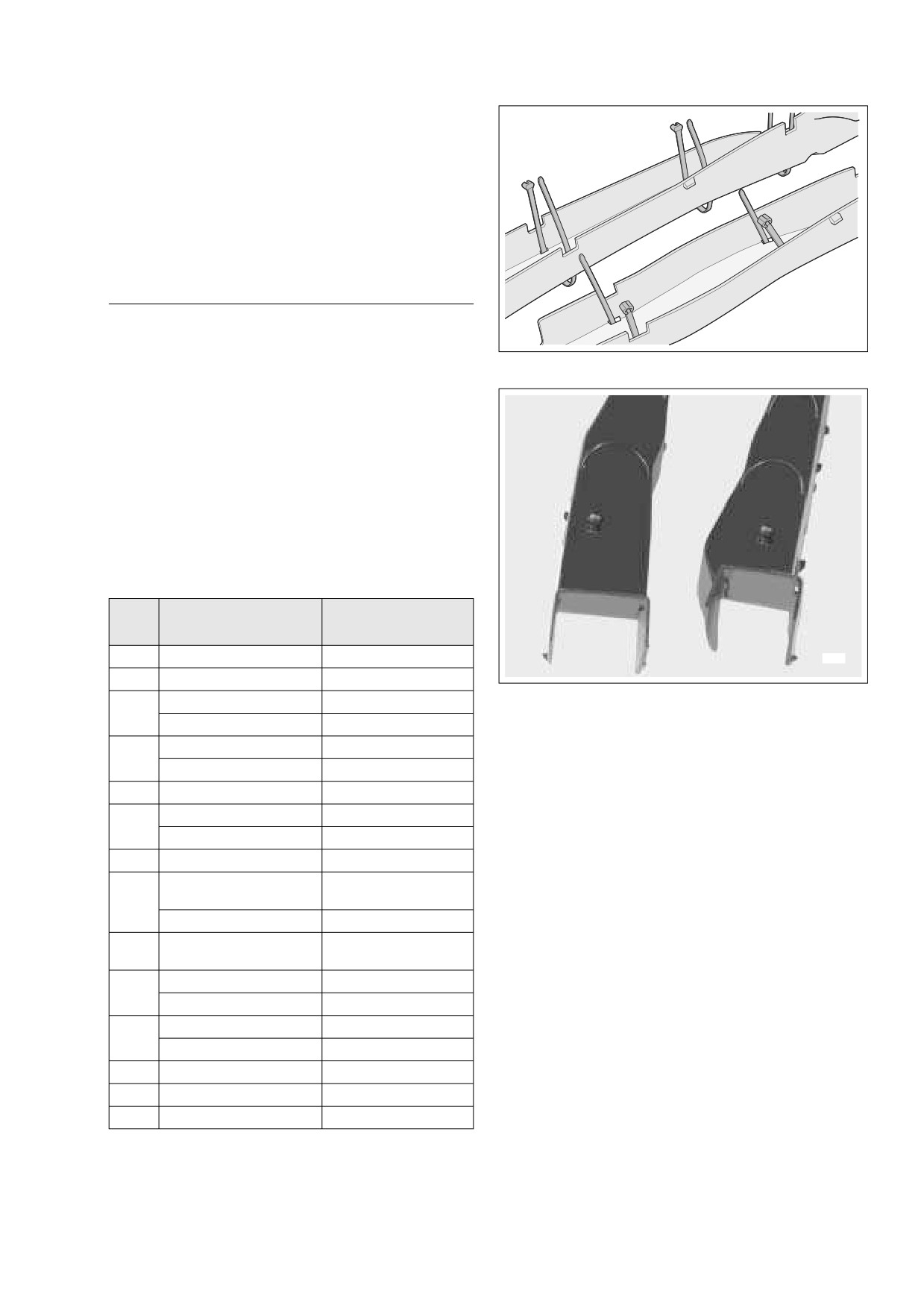
1.
Thread cable straps through slots of new wire trough as
f2399x8x
shown in Figure 8-153. Properly installed, both ends of
the cable strap will be pointing upward. Install all cable
Figure 8-153. Install New Cable Straps in Wire Trough
straps in this fashion.
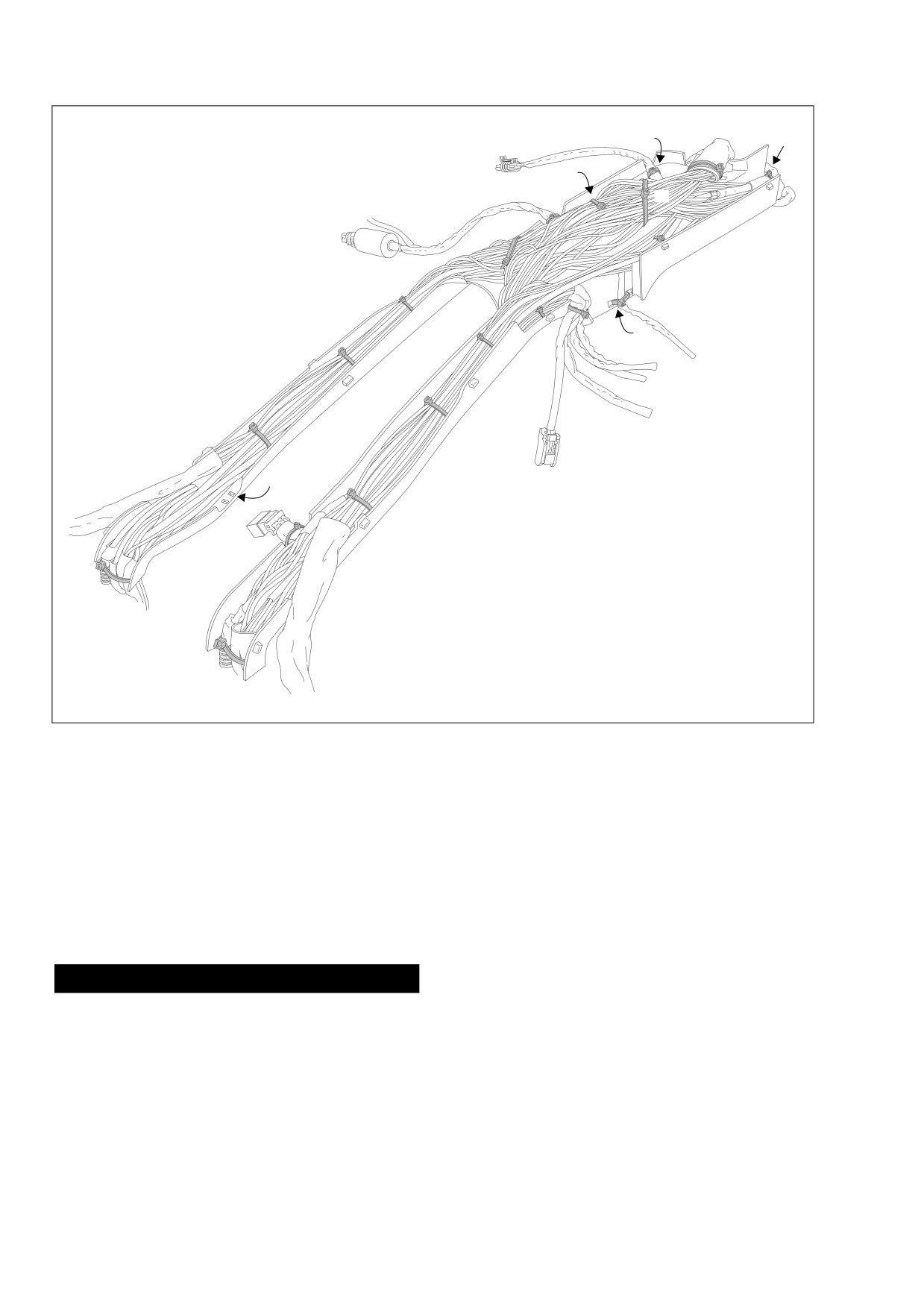
NOTE
Depending upon model, there are a minumum of 17 cable
straps
(carbureted FLHR/S) and a maximum of 20 (fuel
injected FLHTCU). See Figure 8-155 in conjunction with
Table 8-20 below. For example, if installing the wire trough on
a fuel injected FLHTCU, start cable straps in all slots except
18. If installing the wire trough on a carbureted FLHR/S, start
cable straps in all slots except 2, 7, 9 and 19.
Table 8-20. Wire Trough Cable Straps
Cable
Captures
Models
Strap
Conduit/Wire Bundle
1
Main Harness
All
9304
2
Audio Harness
FLHTCU
Figure 8-154. Rear Leg Index Pins
Ignition Coil
All
3
Fuel Gauge
FLHR/C/S
Main Harness
All
2.
Raise wire harness, and from left side of motorcycle,
4
carefully slide wire trough into position on frame
Audio Harness
FLHTCU
backbone.
5
Main Harness
All
3.
Slide wire trough rearward to engage slot at bottom on T-
Main Harness
All
6
stud at center of frame backbone.
Audio Harness
FLHTCU
4.
Gently push index pins on rear legs of wire trough into
7
Front Fuel Injector
Fuel Injected
holes in frame backbone. See Figure 8-154.
TP Sensor, MAP Sensor,
Fuel Injected
IAC and Rear Fuel Injector
5.
Lay harness in wire trough so that the painted lines are
8
adjacent to the cable straps. Start tail end of each cable
MAP Sensor
Carbureted
strap into eyelet, but do not tighten.
TP Sensor, MAP Sensor,
9
Fuel Injected
IAC and Rear Fuel Injector
6.
Adjust harness as necessary, so that the painted lines
are aligned with the cable straps threaded through the
Horn
All
10
wire trough.
ET Sensor
Fuel Injected
7.
Tighten the cable straps and cut any excess cable strap
Main Harness
All
11-17
material.
Audio Harness
FLHTCU
8.
Carefully cut and remove all cable straps not threaded
18
Instrument Console
FLHR/C/S
through the wire trough, that is, those installed just
19
Fuel Tank Harness
FLHX, FLHT/C/U, FLTR
outside the painted lines in step 7 under REMOVAL.
20-21
Main Harness
All
2006 Touring: Electrical
8-117
HOME
3
1
2
6
10
4
11
5
12
8
14
9
7
13
16
15
18
19
17
20
NOTE
Refer to Table 8-20 for reference
21
number identification.
f2429x8x
Figure 8-155. Wire Trough Cable Strap Locations (FLHTCU)
9.
Place cover over wire trough. Starting at the front and
11. Insert bolt through battery positive cable
(red) into
working rearward from side to side, engage catches to
threaded hole of battery positive (+) terminal. Tighten
latch cover. Verify that all latches are fully engaged.
bolt to 60-96 in-lbs (6.8-10.9 Nm).
10. Place battery in battery box, terminal side forward.
12. Insert bolt through battery negative cable (black) into
Rotate the hold-down clamp so that the lip (with rubber
threaded hole of battery negative (-) terminal. Tighten
pad) rests on the edge of the battery. Tighten T40 TORX
bolt to 60-96 in-lbs (6.8-10.9 Nm).
screw to 15-20 ft-lbs (20-27 Nm).
13. Install fuel tank. For carbureted models, see Section 4.7
FUEL TANK (CARBURETED), INSTALLATION (AFTER
1WARNING
COMPLETE REMOVAL), FLHX, FLHT or FLHR/S. For
fuel injected models, see Section 9.4 FUEL TANK (FUEL
Always connect the positive battery cable first. If the
INJECTED), INSTALLATION
(AFTER COMPLETE
positive cable should contact ground with the negative
REMOVAL), FLHXI, FLHT/C/U/I, FLTRI or FLHR/C/S/I.
cable installed, the resulting sparks may cause a battery
explosion which could result in death or serious injury.
8-118
2006 Touring: Electrical
HOME
MAIN HARNESS
8.34
NOTE
REMOVAL
Depending upon model, continue procedure at REMOVAL-
FLHR/C/S
(PART II), REMOVAL- FLTR
(PART II), or
REMOVAL- ALL MODELS (PART I)
REMOVAL- FLHX, FLHT/C/U (PART II).
1.
Remove fuel tank. For carbureted models, see Section
4.7 FUEL TANK
(CARBURETED), COMPLETE
REMOVAL- FLHR/C/S (PART II)
REMOVAL, FLHX, FLHT or FLHR/S. For fuel injected
models, see Section
9.4 FUEL TANK
(FUEL
1.
Remove the headlamp assembly. See Section 8.11
INJECTED), COMPLETE REMOVAL, FLHXI, FLHT/C/
HEADLAMP (FLHR/C/S, FLHX, FLHT/C/U), HEAD-
U/I, FLTRI or FLHR/C/S/I.
LAMP ASSEMBLY, REMOVAL.
2.
Unthread bolt and remove battery positive cable (red)
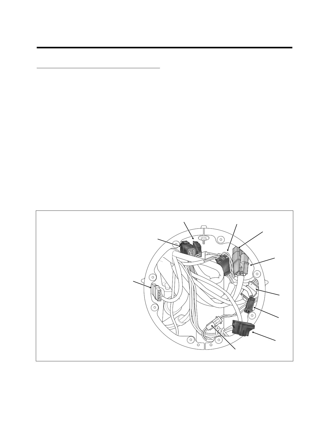
2.
See Figure
8-156. Reaching inside the headlamp
from battery positive
(+) terminal.
(Battery negative
nacelle, disconnect main harness as follows:
cable already removed under FUEL TANK, COMPLETE
● Front fender tip lamp jumper harness connector
REMOVAL.)
[32], 2-place Multilock (black); used on FLHR only.
3.
Loosen T40 TORX screw and move lip of hold-down
● Auxiliary lamps connector [73], 2-place Multilock
clamp off edge of battery. Remove battery from battery
(white); used on FLHR/C only.
box.
● Auxiliary lamps switch connector
[109],
4-place
4.
Remove left side saddlebag. See Section 2.26 SAD-
DLEBAG, REMOVAL.
Amp; used on FLHR/C only.
5.
Gently pull left side cover from frame downtubes (no
● Accessory switch connector [67], 4-place Amp.
tools required).
● Right handlebar switch controls connector [22], 6-
6.
Repeat steps 4-5 to remove right side saddlebag and
place Deutsch (black); T-stud on fork stem nut lock-
side cover.
plate (left side).
f2212x8x
[159]
[31]
[24]
[22]
[158]
[109]
[67]
[22] Right Handlebar Switches
[24] Left Handlebar Switches
[31] Front Turn Signals
[32] Front Fender Tip Lamp (Used on FLHR Only)
[32]
[38] Headlamp
[67] Accessory Switch
[73] Auxiliary Lamps (Used on FLHR/C Only)
[109] Auxiliary Lamps Switch (Used on FLHR/C Only)
[38]
[158] Cruise On/Off Switch (Used on FLHRC Only)
[73]
[159] Cruise Set/Resume Switch (Used on FLHRC Only)
Figure 8-156. Headlamp Nacelle - Main Harness Connectors (FLHR/C/S)
2006 Touring: Electrical
8-119
HOME
f2095x8x
4
5
1
5
3
6
1.
Ignition/Light Key Switch Connector [33]
2
5
2.
Indicator Lights Connector [21]
3.
Speedometer Connector [39]
5.
Flexible Clip (3)
4.
Odometer Reset Switch
6.
Plastic Clip
Figure 8-157. Instrument Console Assembly - Main Harness Connectors (FLHR/C)
● Cruise set/resume switch connector [159], 2-place
7.
Bend back flexible clamps on inboard side of instrument
Deutsch (black); used on FLHRC only.
console as necessary to release main harness conduit.
Set instrument console aside.
● Front turn signal lamps connector [31], 6-place Mul-
tilock; anchored in hole of fork stem nut lock plate
NOTE
(left side).
Continue procedure at REMOVAL- ALL MODELS (PART III).
● Left handlebar switch controls connector [24], 6-
place Deutsch (gray); T-stud on fork stem nut lock-
plate (left side).
REMOVAL- FLHX, FLHT/C/U (PART II)
● Cruise on/off switch connector [158], 2-place Deut-
sch (gray); used on FLHRC only.
1.
Remove the outer fairing and windshield. See Section
2.30 UPPER FAIRING/WINDSHIELD (FLHX, FLHT/C/
3.
Carefully pull main harness rearward under right side of
U), OUTER FAIRING/WINDSHIELD, REMOVAL.
headlamp nacelle allowing conduit and connectors to
2.
Cut cable strap to release convoluted tubing of intercon-
hang over top of engine guard.
nect harness and conduit of main to interconnect har-
ness connectors [1], [2], [15] and [156] from right fairing
4.
Remove screw and P-clamp to release main harness
from right side of steering head.
bracket.
3.
See Figure 8-158. Disconnect main harness from inter-
5.
See Figure 8-157. Moving to inboard side of instrument
connect harness as follows:
console, disconnect main harness as follows:
● Main to interconnect harness connector [1], 12-
● Ignition/Light Key Switch connector [33],
3-place
place Deutsch (black); T-stud on right radio support
Packard.
bracket.
● Indicator lights connector [21], 8-place Deutsch.
● Main to interconnect harness connector [2], 12-
place Deutsch (gray); T-stud on right fairing support
● Speedometer connector [39], 12-place Packard.
brace (middle).
● Main to interconnect harness connector [15], 4-
6.
Unthread rubber boot from odometer reset switch and
place Packard (black); anchored in hole at front of
pull switch from hole in instrument console.
right fairing bracket.
8-120
2006 Touring: Electrical
HOME
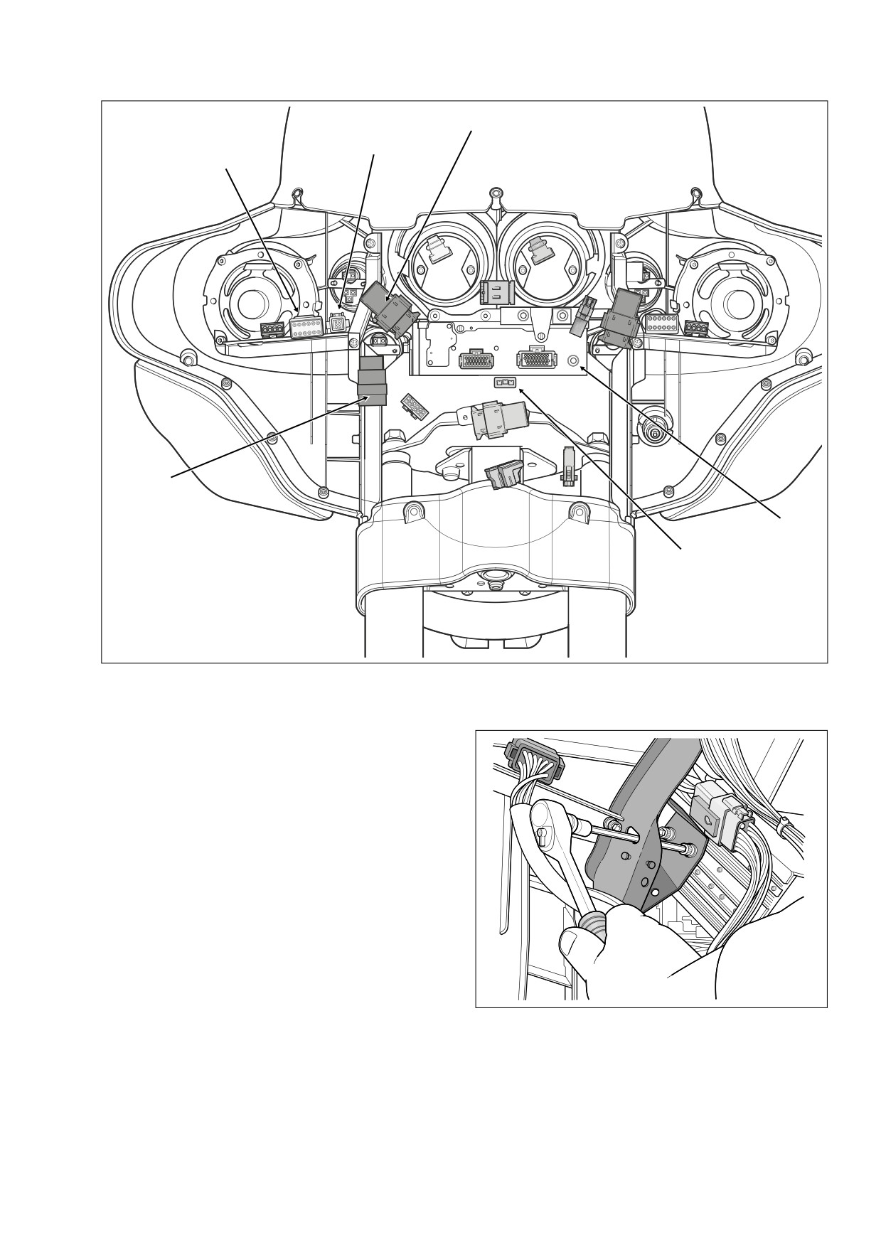
[1]
f2356x8x
[156]
[2]
[15]
[51]
[1] Main to Interconnect Harness
[2] Main to Interconnect Harness
[33]
[15] Main to Interconnect Harness
[33] Ignition Switch
[51] Radio Antenna Cable
[156] Main to Interconnect Harness
Figure 8-158. Inner Fairing - Main Harness Connectors (FLHX,
FLHTC/U)
● Main to interconnect harness connector [156], 6-
place Deutsch (gray); T-stud on right fairing support
brace (inboard side).
4.
See Figure 8-158. Disconnect radio antenna cable. Pro-
ceed as follows:
● Radio antenna cable connector [51]; back of radio
(left side).
5.
See Figure 8-158. Disconnect ignition/light key switch
connector
[33],
3-place Packard, at front of ignition
switch housing. Proceed as follows:
a. Using a long shank ball end socket
(Snap-on®
FABL6E), remove four socket head screws to
release radio (storage box on FLHT) from left and
right radio support brackets. Use oblong holes in
fairing brackets to access screws. See Figure 8-
f1559x8x
159.
b. Carefully cut anchored cable strap to release main
Figure 8-159. Release Radio from Fairing Brackets
harness conduit from bottom right corner of radio.
(FLHTC/U)
2006 Touring: Electrical
8-121
HOME
c. Obtain the IGNITION SWITCH CONNECTOR
REMOVER (HD-45961).
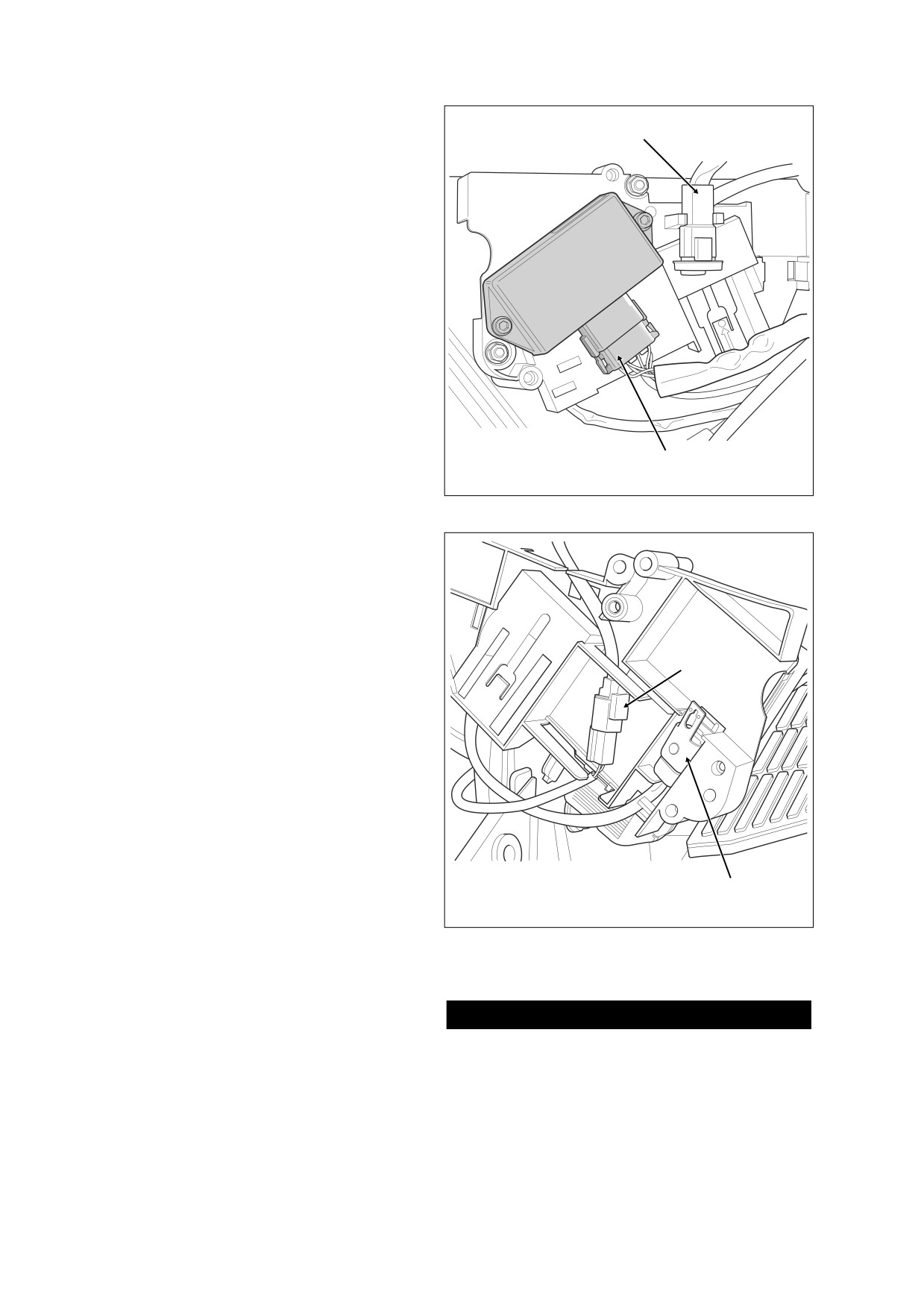
f2375x8x
[91]
d. Lift radio slightly and gently insert end of tool into
slot in ignition switch housing until it stops.
e. Grasping main harness conduit and tool, pull both
at the same time to release socket housing from
ignition switch housing.
6.
Remove screw, main harness ground ring terminal and
P-clamp to release main harness (and audio harness on
FLHTCU models) from right side of steering head.
7.
Carefully pull main harness rearward under right side of
fairing cap allowing conduit and connectors to hang over
top of engine guard.
8.
For FLHTCU models only, see Section 8.37 AUDIO
HARNESS (FLHTCU), REMOVAL, steps 6 and 8.
NOTE
Continue procedure at REMOVAL- ALL MODELS (PART III).
[10] ICM
[10]
[91] Data Link
REMOVAL- FLTR (PART II)
Figure 8-160. Electrical Bracket (Under Right Side Cover)
1.
Remove the inner fairing. See Section 2.31 UPPER
FAIRING/WINDSHIELD
(FLTR), INNER FAIRING,
REMOVAL, steps 1-20.
f1847x8x
2.
Remove screw, two main harness ground ring terminals
and P-clamp to release main harness bundle from right
side of steering head.
NOTE
Continue procedure at REMOVAL- ALL MODELS (PART III).
[65]
REMOVAL- ALL MODELS (PART III)
1.
If cruise equipped, locate the cruise control roll-off
switch plumbed into the idle cable on right side of the
steering head. Push rubber boot on switch forward and
remove insulators from switch spade terminals.
2.
Depending upon whether the motorcycle is carbureted
or fuel injected, proceed as follows:
Carbureted:
a. Remove ignition coil connector [83] and MAP sen-
sor connector [80].
[65] VSS
[142]
[142] P&A Security Siren
b. Remove ICM connector [10]. See Figure 8-160.
c. Gently pull on data link connector [91] to disengage
Figure 8-161. Electrical Bracket (Inboard Side)
from arms on electrical bracket.
d. Remove two flange nuts to release electrical
bracket from studs on side of battery box.
e. On inboard side of electrical bracket, disconnect
CAUTION
VSS connector [65]. See Figure 8-161. Release
connector and conduit from electrical bracket.
Damage to wires can result in electrical problems. Be
sure that rubber boot is present on threaded end of bat-
f.
Release security siren connector [142] and conduit
tery box TORX screw. Replace rubber boot if absent or
from electrical bracket.
damaged. See upper frame of Figure 8-162.
8-122
2006 Touring: Electrical
HOME
g. Pull back boot and disconnect ET sensor connector
8321
[90] at back of front cylinder. Cut cable strap to
release conduit from horn bracket.
h. Returning to right side of motorcycle, disconnect
ECM connector [78].
i.
Gently pull on data link connector [91] to disengage
from arms on electrical bracket.
j.
Locate painted white dot on inboard side of fuse
block [119]. Pressing on dot, gently tug on conduit
Rubber
to release tabs on fuse block from slots in bracket.
Boot
k. Remove two flange nuts to release electrical
bracket from studs on side of battery box.
l.
On inboard side of electrical bracket, disconnect
VSS connector [65]. See Figure 8-161. Release
connector and conduit from electrical bracket.
m. Release security siren connector [142] and conduit
from electrical bracket.
CAUTION
Damage to wires can result in electrical problems. Be
sure that rubber boot is present on threaded end of bat-
tery box TORX screw. Replace rubber boot if absent or
damaged. See upper frame of Figure 8-162.
n. Note that a section of the main harness conduit
runs forward of the front battery box TORX screw.
Pull conduit to the rear of the screw, and then feed
8319
f2363x9x
Figure 8-162. Remove Main Harness From Vehicle
[84A]
[87A]
Front
g. Note that a section of the main harness conduit
runs forward of the front battery box TORX screw.
Pull conduit to the rear of the screw, and then feed
ICM, data link, VSS, and security siren conduit and
connectors through opening into battery box. See
upper and lower frames of Figure 8-162.
Fuel Injected:
a. Remove air cleaner and backplate. See Section 4.5
AIR CLEANER, REMOVAL.
b. Remove front fuel injector connector [84].
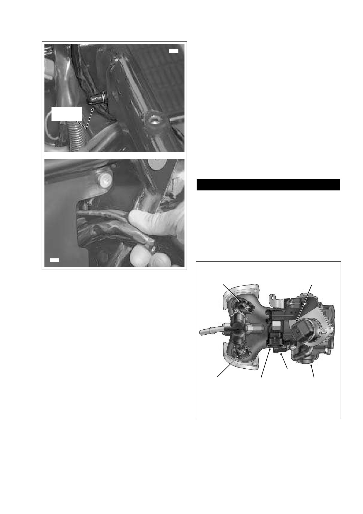
[89A]
c. Remove IAC connector [87] and MAP sensor con-
[85A]
[80A]
[88A]
nector [80]. See Figure 8-163.
d. Remove TP sensor connector [88] and IAT sensor
[80A] MAP Sensor
[87A] IAC
connector [89].
[84A] Front Fuel Injector
[88A] TP Sensor
e. Remove rear fuel injector connector [85].
[85A] Rear Fuel Injector
[89A] IAT Sensor
f.
Moving to left side of motorcycle, remove ignition
coil connector [83] from left side of ignition coil.
Figure 8-163. Induction Module Assembly (Top View)
2006 Touring: Electrical
8-123
HOME
7
f2427x8x
1
6
5
4
3
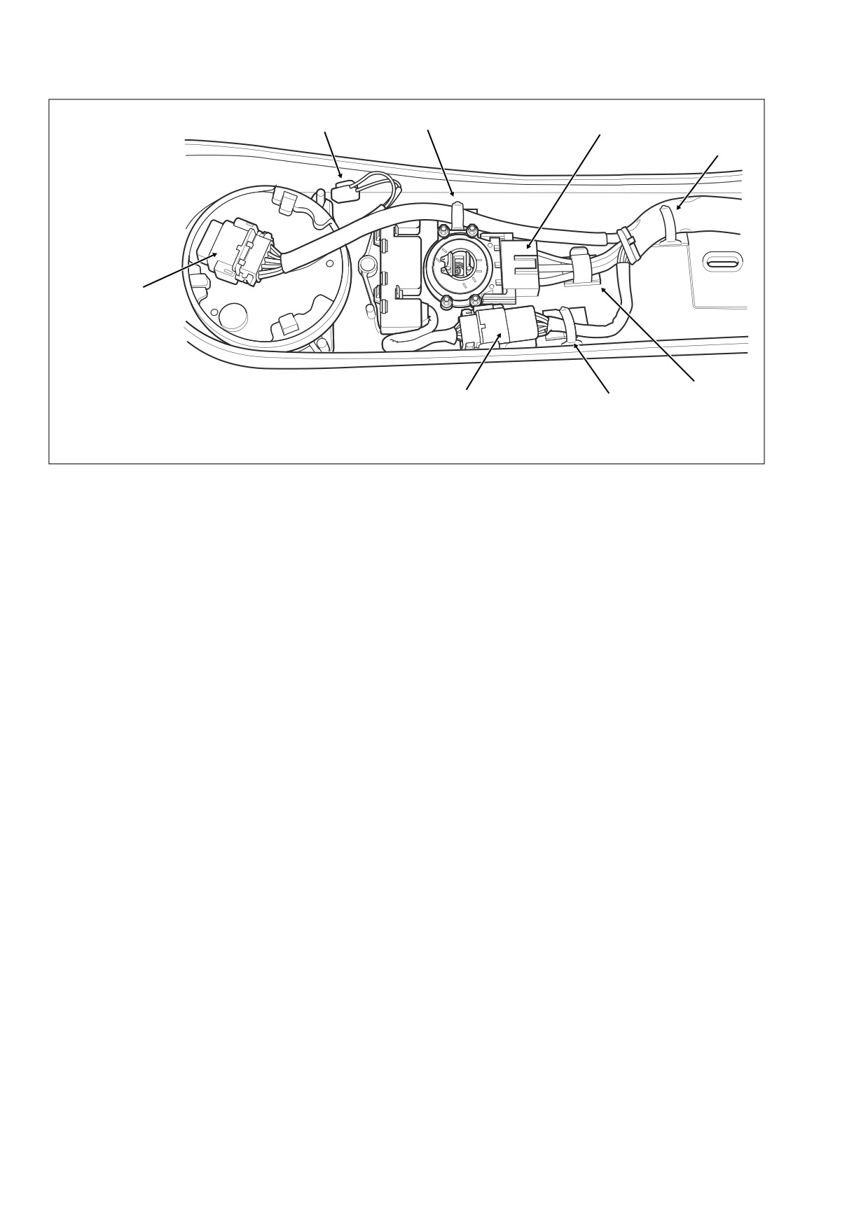
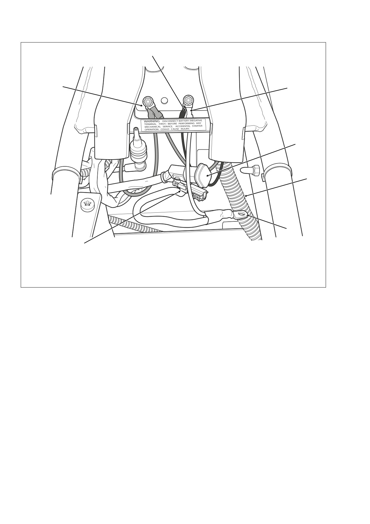
2
1.
Main Harness Ground Ring Terminals (2)
2.
B+ Connector [160]
5.
Accessory Connector [4]
3.
Battery Negative Cable
6.
Chassis Ground Cable
4.
Battery Positive Cable
7.
Main Harness Ground Ring Terminal
Figure 8-164. Upper Frame Cross Member (Under Seat) - Main Harness Connectors (FLHX, FLHTC/U)
ECM, fuse block, data link, VSS, and security siren
6.
Moving to right side of motorcycle, pull back boot at top
conduit and connectors through opening into bat-
of starter housing and remove flange nut and main
tery box. See upper and lower frames of Figure 8-
power cable ring terminal from post. Release cable from
162.
clip anchored to T-stud at front of battery tray. Draw main
power cable to left side of motorcycle.
3.
Moving to left side of motorcycle, remove acorn nut to
release horn bracket from rubber mount stud. Pull elbow
7.
Carefully cut anchored cable strap to release fuse block
terminals from spade contacts and release conduit from
conduit from fuse block bracket. Pull fuse block from
J-clamp.
tabs on bracket.
4.
Remove flange nut (10 mm) from left side ground stud
on upper frame crossmember. Remove two main har-
8.
Remove the fuse block cover. Raise lipped side slightly
ness ground ring terminals (with orange tape). Repeat
to disengage slots from tabs on fuse block.
step to remove main harness ground ring terminal (with-
9.
If cruise equipped, lift the locking latch and remove
out orange tape) and chassis ground ring terminal from
cruise module connector [17]. From inside battery box,
right side ground stud.See Figure 8-164.
remove three flange bolts. Carefully pull cruise module
5.
Depress latches on maxi-fuse holder and then slide
away from side of battery box exercising caution to avoid
cover rearward to disengage tongue from groove in fuse
losing grommets.
block cover.
8-124
2006 Touring: Electrical
HOME
10.
Disconnect the rear fender lights connector [7], 8-place
e. Draw radio antenna cable and rear facia lamp con-
Multilock, anchored at front of rear fender. Detach pin
conduit forward to area of fuse block bracket and
housing from anchor.
allow to hang with other main harness branches.
11.
Release ignition keyswitch and starter relays by pulling
FLHTC/U:
anchors on rubber molding from holes in frame weld-
a. Open Tour-Pak and proceed as follows:
ment at rear of battery box. Remove relays and molding
from connectors. Push connectors down into space
FLHTC: Remove rubber mat.
below frame weldment.
FLHTCU: Open map pocket and remove acorn nuts
12.
Locate the TSM/TSSM inside hole of frame weldment on
with flat washers. Remove map pocket and molded
opposite side. Depress tab at front of spring clip and lift
liner from Tour-Pak.
to release legs from holes in weldment. Remove module
b. On Ultra models, depress external latch and remove
and disconnect TSM/TSSM connector [30], 12-place
bulb socket from left side wrap-around light.
Deutsch. Push connector down into space below frame
weldment.
c. Rotate knurled ring in a counterclockwise direction
to separate pin and socket halves of radio antenna
13.
Pull rear fender lights, ignition keyswitch and starter
cable connector [51]. Release cable from two adhe-
relays, and TSM/TSSM conduit and connectors out
sive clips at bottom of Tour-Pak.
through opening above rear of fuse block bracket and
allow to hang on left side of motorcycle.
d. On FLHTCU models, disconnect Tour-Pak lights
connector [12], 3-place Multilock.
14.
Depending upon model, proceed as follows:
e. Pull grommet into Tour-Pak and remove from main
FLHR/C/S: Move to step 15.
harness conduit.
FLTR:
f.
Pull Tour-Pak lights and radio antenna cable con-
nectors through hole at front of Tour-Pak. Cut cable
a. On left side of motorcycle, remove bolt (with flat
strap to release conduit from luggage rack rail.
washer) to remove passenger seat strap and sad-
dlebag front mounting bracket. Remove Phillips
g. Draw Tour-Pak lights and radio antenna cable con-
screw and chrome frame tube cover.
nectors forward to area of fuse block bracket and
allow to hang with other main harness branches.
b. Carefully cut cable strap to release radio antenna
cable from shoulder of upper frame tube (just in
h. For FLHTCU models only, see Section 8.37 AUDIO
HARNESS (FLHTCU), REMOVAL, steps 10-17.
front of air valve mounting bracket). Cut cable strap
to release radio antenna cable from slotted hole in
15.
Carefully cut two cable straps securing main harness to
rear fender support.
left upper frame tube.
c. At bottom of radio antenna bracket, rotate knurled
16.
Cut anchored cable strap to release accessory connec-
ring to separate pin and socket halves of radio
tor [4] and B+ connector [160] from left side of frame
antenna cable connector [51].
crossmember (in front of battery box). See Figure 8-164.
d. Draw radio antenna cable forward to area of fuse
17.
Cut cable strap to release vapor valve from mounting
block bracket and allow to hang with other main har-
bracket. Move vapor valve out of the way to facilitate har-
ness branches.
ness removal.
18.
Alternately feed branches of main harness hanging on
FLHX:
left side of motorcycle into battery box through opening
a. On left side of motorcycle, remove bolt (with flat
above fuse block bracket. For best results, feed one
washer) to remove passenger seat strap and sad-
length of conduit through at a time drawing the fuse
dlebag front mounting bracket. Remove Phillips
block through the opening last. Pulling branches out of
screw and chrome frame tube cover.
battery box, allow conduit and connectors to hang on left
side of frame backbone.
b. Carefully cut cable strap to release radio antenna
cable from shoulder of upper frame tube (just in
19.
Moving to front right side of motorcycle, locate CKP sen-
front of air valve mounting bracket). Cut cable strap
sor connector [79], 2-place Deutsch, fixed to bracket at
to release radio antenna cable from slotted hole in
bottom of voltage regulator. Push connector toward right
rear fender support.
side of motorcycle to disengage attachment clip from T-
stud on bracket. Lift connector off T-stud. Depress button
c. At bottom of radio antenna bracket, rotate knurled
on socket terminal side and pull apart pin and socket
ring to separate pin and socket halves of radio
halves.
antenna cable connector [51].
20.
Disconnect voltage regulator connector
[77],
2-place
d. Disconnect rear facia lamp connector [12], 3-place
Lyall, at bottom right side of voltage regulator. Proceed
Multilock, inboard of upper frame tube.
as follows:
2006 Touring: Electrical
8-125
HOME
f2317x2x
Battery
Box
See Figure 8-164.
6
1
5
4
3
2
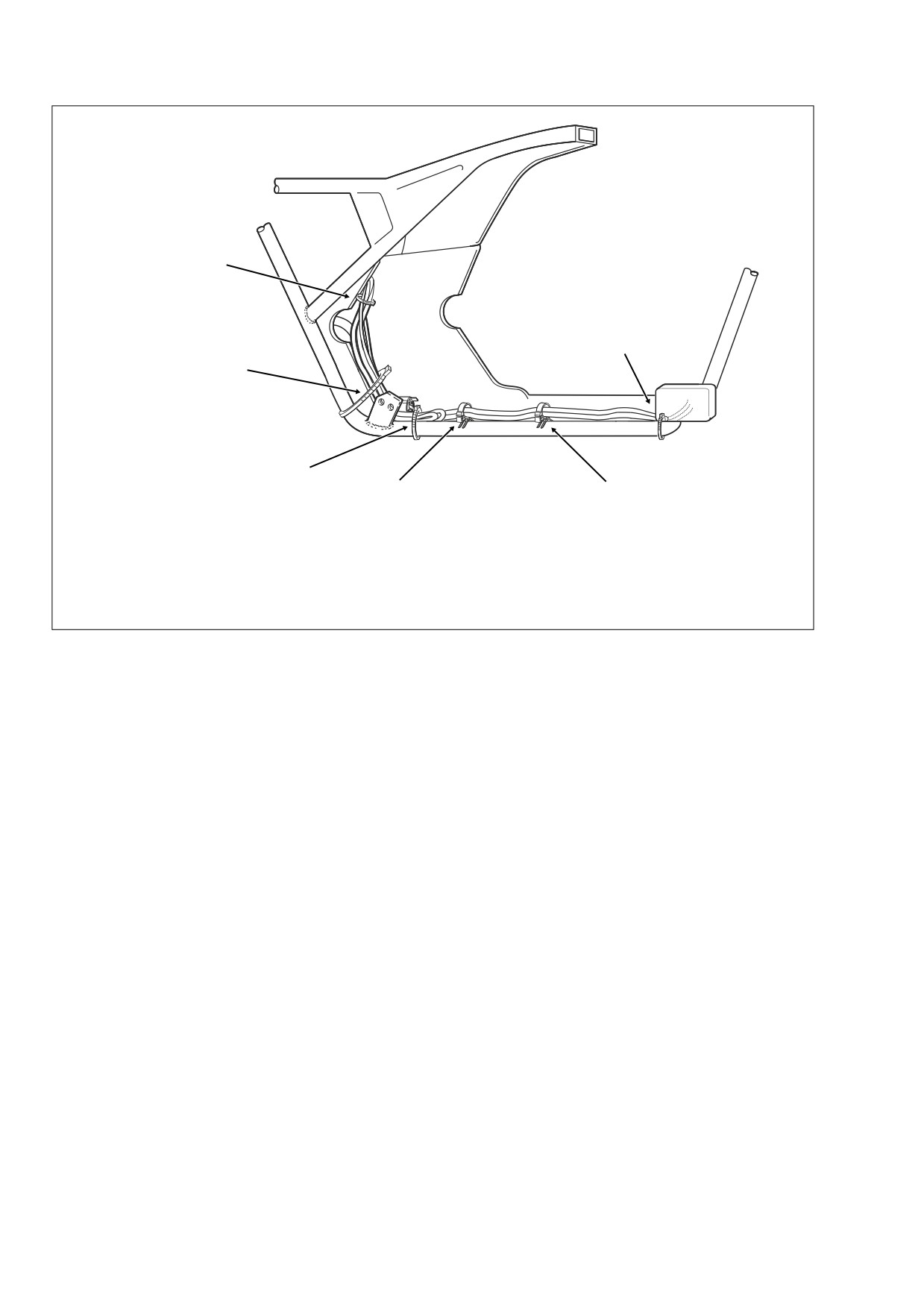
1.
Cable Strap: Captures Main Harness Conduit and Lower Frame Tube
2.
Cable Clip: Captures Main Harness Conduit and Rear Brake Line
3.
Cable Clip: Captures Main Harness Conduit and Rear Brake Line
4.
Cable Strap: Captures Rear Brake Light Switch Wires, Main Harness Conduit and Lower Frame Tube
5.
Cable Strap: Captures Main Harness Conduit and Frame Downtube
6.
Anchored Cable Strap: Captures Main Harness Conduit, Neutral Switch Conduit and VSS Cable
Figure 8-165. Cable Strap Locations (Right Side View)
a. Loosen locknuts on studs of lower frame crossmem-
24. Remove starter solenoid connector [128] at top of starter
ber.
housing.
b. Lift voltage regulator and release voltage regulator
25. Remove two elbow connectors from neutral switch
connector conduit and CKP sensor connector con-
posts.
voluted tubing from P-clip at front of right side leg of
voltage regulator.
26. Pull two socket terminals from spade contacts on rear
c. Pull away locking latch and remove socket of volt-
brake light switch. Cut cable strap to free rear brake light
age regulator connector.
switch wires from lower frame tube.
21.
Locate oil pressure switch/sender at front right side of
27. Cut cable strap at rear of rear brake light switch bracket
crankcase. On FLHR/C/S models, pull elbow from post
to release main harness conduit from frame downtube.
of oil pressure switch. On FLHX, FLHT/C/U and FLTR
28. Cut anchored cable strap in hole of frame downtube
models, remove Delphi connector from oil pressure
(inboard of rear swingarm bracket) to release VSS cable,
sender.
main harness and neutral switch conduit.
22.
Cut cable strap to free main harness conduit (leading to
oil pressure sender and CKP sensor connectors) from
29. Draw neutral switch wires out from under starter hous-
inboard side of rear brake pedal weldment. See Figure
ing. For best results, reach in under right side of battery
8-165.
box.
23.
Open two cable clips on lower frame tube T-studs. Free
30. Carefully pull voltage regulator, CKP sensor, oil pressure
main harness conduit from cable clips.
switch/sender, rear brake light switch, starter solenoid,
NOTE
and neutral switch conduit and connectors rearward and
then feed up through opening at front of battery tray into
For best results, insert blade of small screwdriver into gap at
battery box. See lower frame of Figure 8-162.
side of clip and gently rotate end of screwdriver to pop open.
8-126
2006 Touring: Electrical