Harley Davidson FLHRC 2006. Maintenance & Repair Manual - page 6
HOME
7.
Install pad pins, but do not fully tighten.
1
8.
Pump rear brake pedal to move inside pistons out until
they contact inside brake pad.
9.
Pry the outside pad back pushing the pistons into their
bores. Use a putty knife with a wide thin blade to avoid
scoring or scratching the brake disc.
10. Verify that inside pad is captured between brake disc
and pistons. Completely remove pad pins to free outside
brake pad. Note the orientation of the pad.
11. Install new outside brake pad using the same orienta-
tion. Curved portion of pad must face rear of motorcycle.
If the inside pad moved during the previous step, rein-
stall.
f2026x2x
2
3
NOTE
1.
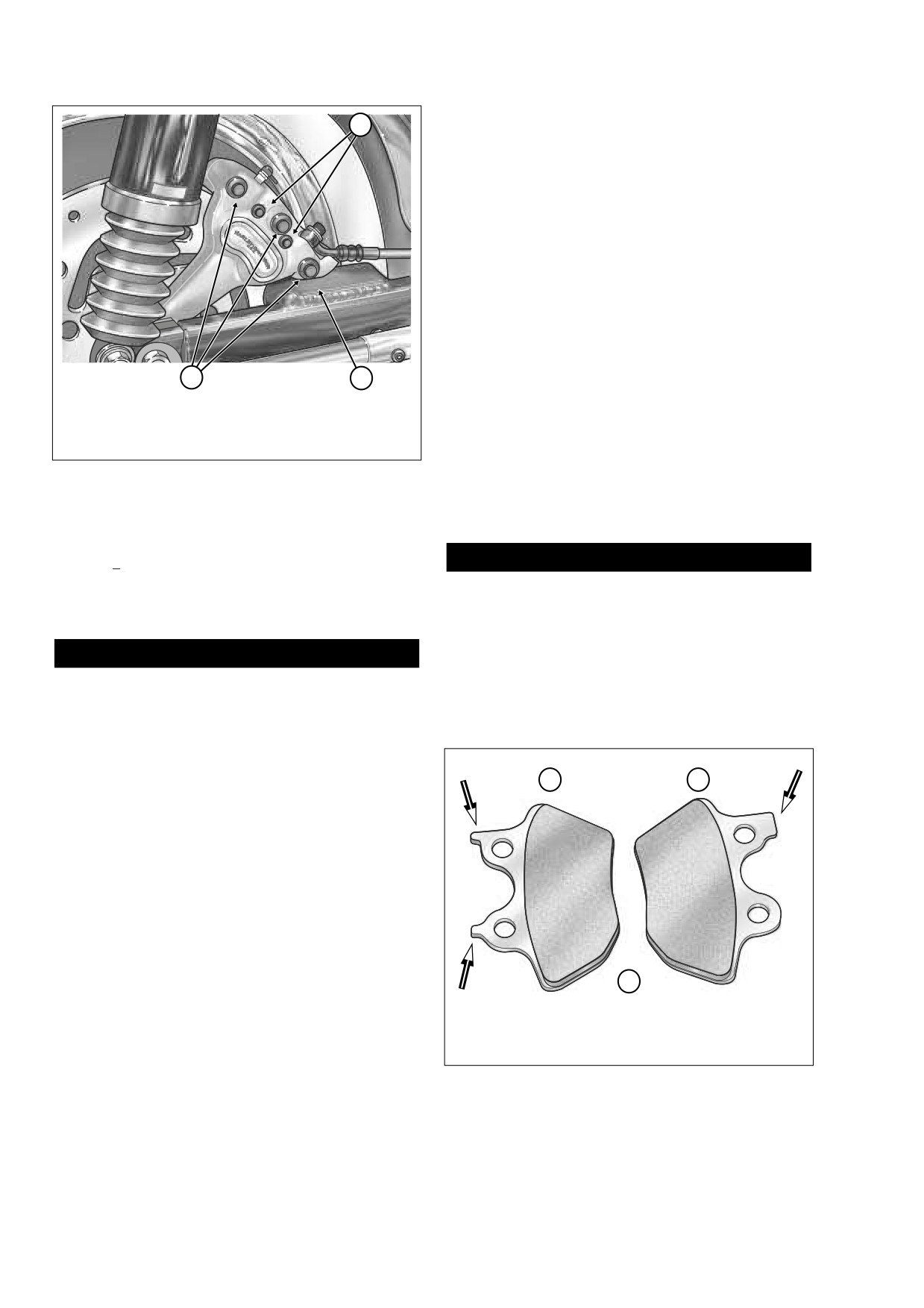
Pad Pins
Replacing one pad at a time keeps the anti-rattle spring in
2.
Bridge Bolts
place. Remove both pads to remove or replace the spring.
3.
Anchor Weldment
12. Inspect pad pins. See CLEANING AND INSPECTION,
step 4.
Figure 2-65. Loosen Both Pad Pins
13. Install two pad pins and tighten to 180-200 in-lbs (20.3-
22.6 Nm).
IMPORTANT NOTE
Immediately wipe up any brake fluid spillage with a
1WARNING
clean, dry, soft cloth. Follow up by thoroughly wiping
affected area with a clean, damp, soft cloth (small spills)
After servicing brakes and before moving motorcycle,
or washing with a large quantity of soapy water (large
pump brakes to build brake system pressure. Insuffi-
spills).
cient pressure can adversely affect brake performance,
which could result in death or serious injury. (00279a)
CAUTION
14. Pump rear brake pedal to move pistons out until they
To prevent dirt and other contaminants from entering the
contact both brake pads. Verify piston location against
master cylinder reservoir, thoroughly clean the cover
pads.
before removal.
3.
Remove two Phillips screws to release cover from rear
master cylinder reservoir.
2
1
NOTE
As the pistons are pushed back into the caliper, fluid level
may rise more than 1/4 inch (6.4 mm) and overflow the reser-
voir. Watch the fluid level as the pistons are retracted and
remove fluid from the reservoir if necessary.
4.
Pry the inside pad back pushing the pistons into their
bores. Use a putty knife with a wide thin blade to avoid
scoring or scratching the brake disc.
NOTE
Do not completely pull pad pins from caliper during the next
step. Completely removing pad pins at this time will make
f2156x2x
3
assembly difficult.
5.
Once the pistons have been retracted, pull the pad pins
1.
Outboard Pad
part way out until the inside pad drops free. Note the ori-
2.
Inboard Pad
Right Side
entation of the pad.
3.
Faces Rear
6.
Install new inside brake pad using the same orientation.
Figure 2-66. Rear Brake Pad Locations
Curved portion of pad must face rear of motorcycle.
2-56
2006 Touring: Chassis
HOME
1.
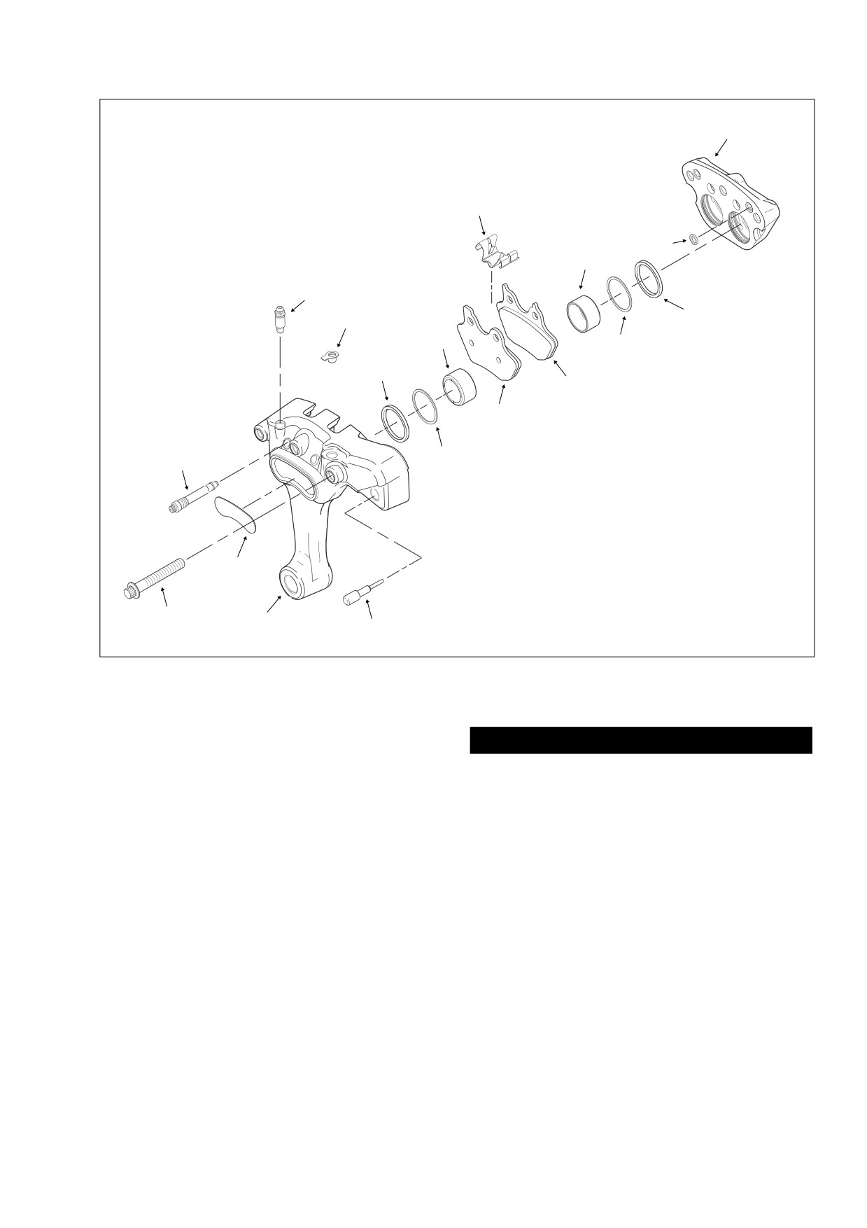
Bridge Bolt (3)
12. Inner Brake Pad
15
2.
Pad Pin (2)
13. Anti-Rattle Spring
3.
Decal
14. Crossover O-Ring (2)
4.
Outside Caliper Housing
15. Inside Caliper Housing
5.
Rubber Damper
6.
Bleeder Valve
13
7.
Bleeder Valve Cap
8.
Square Seal (4)
9.
Wiper (4)
14
10. Piston (4)
10
11. Outer Brake Pad
6
8
7
10
9
8
12
11
9
2
3
1
4
5
f2072x2x
Figure 2-67. Rear Brake Caliper Assembly (Right Side)
15. Verify that brake fluid level is 1/4 inch (6.4 mm) below top
of reservoir with master cylinder in a level position. Add
1WARNING
DOT 4 BRAKE FLUID, if necessary.
After repairing the brake system, test brakes at low
16. Install the master cylinder reservoir cover, but first verify
speed. If brakes are not operating properly, testing at
high speeds can cause loss of control, which could
that the cover gasket bellows is not extended or brake
result in death or serious injury. (00289a)
fluid will be ejected from the reservoir. Install two Phillips
screws and alternately tighten to
6-8 in-lbs
(0.7-0.9
20. Test ride the motorcycle. If the brakes feel spongy, bleed
Nm).
the system again. See Section
2.14 BLEEDING
HYDRAULIC BRAKES.
17. Install master cylinder reservoir cover. Install two Phillips
screws to fasten cover to reservoir and tighten to 6-8 in-
NOTE
lbs (0.7-0.9 Nm).
To allow new brake pads to “wear in” properly with the brake
disc, avoid making hard stops for the first 100 miles (160 km).
18. Install right side saddlebag. See Section 2.26 SADDLE-
BAG, INSTALLATION.
19. Test operation of brake lamp with the rear brake applied
and the Ignition/Light Key Switch turned to IGNITION.
2006 Touring: Chassis
2-57
HOME
5.
Remove caliper from anchor weldment on rear swing-
arm.
CALIPER DISASSEMBLY
1.
See Figure 2-65. Remove two pad pins. Remove brake
pads from caliper housings.
2.
Remove three bridge bolts and separate inside and out-
side caliper housings.
3.
Remove anti-rattle spring from channel around boss in
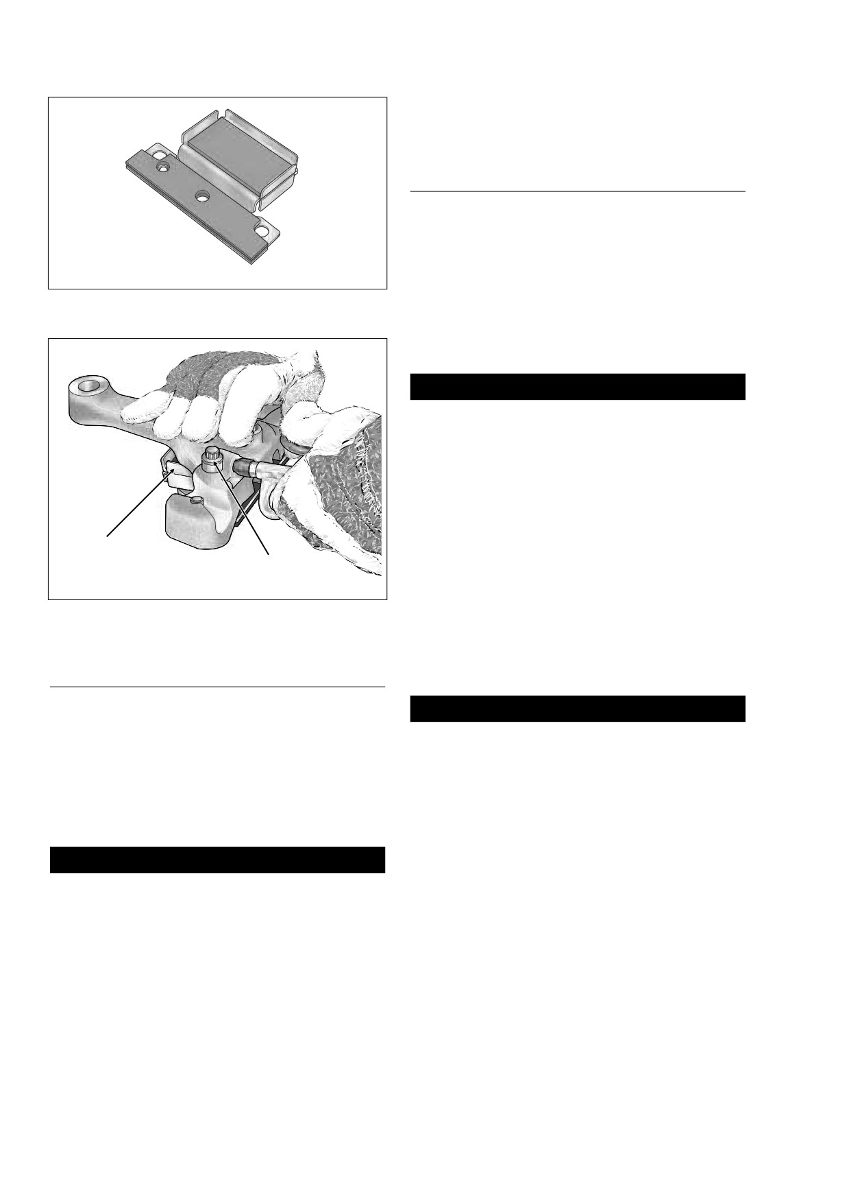
Figure 2-68. Brake Caliper Piston Remover
outside caliper housing.
(Part No. HD-43293A)
4.
If damaged, cut anchor of rubber damper and remove.
5.
Remove bleeder valve, if damaged.
f1781x2x
1WARNING
Compressed air can pierce the skin and flying debris
from compressed air could cause serious eye injury.
Wear safety glasses when working with compressed air.
Never use your hand to check for air leaks or to deter-
mine air flow rates. (00061a)
6.
Remove four pistons as follows:
a. Obtain BRAKE CALIPER PISTON REMOVER (Part
No. HD-43293A). See inset of Figure 2-68.
Brake Caliper
Piston Remover
Bridge
b. Seat tool in outside caliper housing aligning holes in
Bolt
tool with three bridge bolt holes in housing. Place
inside caliper housing over tool aligning bridge bolt
Figure 2-69. Direct Compressed Air Into Banjo Bolt Hole
holes with three holes in tool.
c. Install bridge bolts and tighten securely.
d. If the bleeder valve was removed, reinstall finger
CALIPER REMOVAL
tight or place a gloved finger over the valve hole.
NOTE
CAUTION
If only replacing brake pads, see REAR BRAKE PAD
To prevent air from escaping through the banjo bolt hole,
REPLACEMENT in this section.
and to avoid scratching or nicking the banjo seating sur-
face, use only a tapered, rubber tipped nozzle on air
1.
Block motorcycle underneath frame so rear wheel is
hose. Loss of air pressure will keep the pistons from
raised off the ground.
moving, while any damage to the banjo seating surface
2.
Remove saddlebags. See Section 2.26 SADDLEBAG,
requires caliper replacement.
REMOVAL.
e. Using a tapered, rubber-tipped nozzle on the air
hose, apply low pressure compressed air into the
CAUTION
banjo bolt hole to force pistons into contact with
Damaged banjo bolt surfaces will leak when reassem-
cushion of tool. See Figure 2-69.
bled. Prevent damage to seating surfaces by carefully
f.
Remove bridge bolts and separate caliper housings.
removing brake line components.
g. Remove pistons from caliper piston bores. For best
3.
Remove banjo bolt and two steel/rubber washers to
results, wiggle pistons slightly while pulling.
detach rear brake line from caliper. Discard washers.
4.
Remove rear wheel. See Section 2.4 REAR WHEEL,
7.
Remove two crossover O-rings from inside caliper hous-
REMOVAL, steps 2-7.
ing. Discard O-rings.
2-58
2006 Touring: Chassis
HOME
c. Check rubber damper for cuts, tears or signs of
f1779x2x
deterioration.
d. Always replace wipers, square seals and crossover
O-rings after caliper disassembly.
1WARNING
Always replace brake pads in complete sets for correct
and safe brake operation. Improper brake operation
could result in death or serious injury. (00111a)
3.
Inspect brake pads and discs. See INSPECTION at the
beginning of this section.
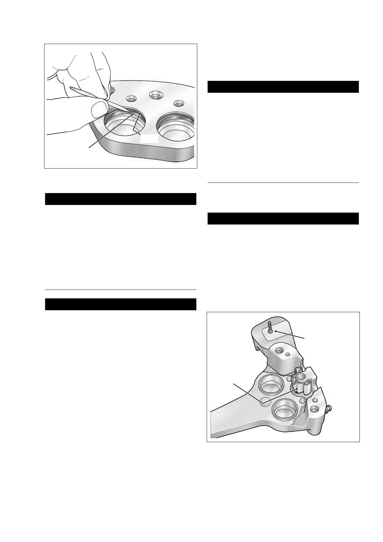
Wiper
4.
Inspect pad pins for wear and grooving. Replace both
Square
pins if wear of either pin exceeds 0.015 inch (0.38 mm).
Seal
Figure 2-70. Remove Wipers and Square Seals
CALIPER ASSEMBLY
From Piston Bores
1.
Install new square seals into caliper piston bores.
CAUTION
2.
Install new wipers into caliper piston bores.
Do not use metal objects to remove parts from caliper
piston bores or damage will occur. Damaged pistons or
CAUTION
bores will leak when reassembled. Use a wooden tooth-
pick to assist in the removal of parts, if necessary.
Do not use DOT 4 brake fluid for lubrication or in-
creased lever travel will result.
8.
Using a wooden toothpick, remove wiper and square
seal from each piston bore. Discard wipers and seals.
3.
Lubricate the following areas using a thin film of G.E.
See Figure 2-70.
VERSILUBE® #G322L SILICONE GREASE (marked
“Piston Lube” in the service parts kit):
● Inside diameter of square seals and wipers.
CLEANING AND INSPECTION
● Caliper piston bores.
● Nose radius and outside diameter of piston.
1WARNING
Use denatured alcohol to clean brake system compo-
f1782x2x
nents. Do not use mineral-based solvents (such as gaso-
line or paint thinner), which will deteriorate rubber parts
even after assembly. Deterioration of these components
Rubber Damper
can cause brake failure, which could result in death or
Anchor Bead
serious injury. (00291a)
1.
Clean all parts with denatured alcohol or DOT 4 BRAKE
FLUID. Wipe parts dry with a clean, lint free cloth. Blow
Anti-Rattle
out drilled passages and bores with a clean air supply.
Spring
Do not use a wire or similar instrument to clean drilled
passages.
2.
Carefully inspect all components. Replace any parts that
appear damaged or worn.
a. Check pistons for pitting, scratching or corrosion on
face and also on ground surfaces.
b. Inspect caliper piston bore. Replace caliper if bore
shows signs of pitting or corrosion. Do not hone
bore for reuse.
Figure 2-71. Install Anti-Rattle Spring
2006 Touring: Chassis
2-59
HOME
NOTE
2.
Connect brake line to caliper using two new steel/rubber
All other surfaces must be kept clean and dry for assembly.
washers and banjo bolt. Tighten bolt to
17-22 ft-lbs
(23.0-29.8).
4.
Carefully insert pistons into bores by hand. If resistance
is felt, remove piston and verify that both seal and wiper
are properly installed.
CAUTION
5.
Install new crossover O-rings into two grooves on inside
DOT 4 brake fluid will damage painted and molded-in
caliper housing.
color surfaces it comes in contact with. Always use cau-
6.
Assemble caliper housings as follows:
tion and protect surfaces from spills whenever brake
work is performed. Failure to comply can result in cos-
a. Install bleeder valve on outside caliper housing, if
metic damage. (00239a)
removed. Tighten valve to 80-100 in-lbs (9.0-11.3
Nm). Install bleeder valve cap.
b. Place outside caliper housing on workbench with
IMPORTANT NOTE
decal side down. Place anti-rattle spring in channel
Immediately wipe up any brake fluid spillage with a
around boss. Spring is not directional. See Figure 2-
clean, dry, soft cloth. Follow up by thoroughly wiping
71.
affected area with a clean, damp, soft cloth (small spills)
c. Mate inside and outside caliper housings and
or washing with a large quantity of soapy water (large
loosely install two bridge bolts.
spills).
d. Tighten bridge bolts to 28-38 ft-lbs (37.9-51.5 Nm).
e. If rubber damper was removed, lubricate anchor of
1WARNING
new damper with isopropyl alcohol or glass cleaner
and install by pulling rubber bead through hole in
Use only fresh, uncontaminated DOT 4 brake fluid. Fluid
outside caliper housing, as shown in Figure 2-71.
containers that have been opened may have been con-
f.
Verify that anti-rattle spring is still seated.
taminated by dirt or moisture. Use of contaminated
brake fluid may adversely affect braking ability and lead
NOTE
to brake failure which could result in death or serious
injury.
All calipers (both front and rear) use the same brake pad set.
IMPORTANT NOTE
7.
Install new brake pads into caliper with the friction mate-
rial facing the brake disc opening. Also, be sure that the
The shelf life of a bottle of unopened DOT 4 brake fluid is
pad is oriented so that the curved side faces the rear of
one year. The shelf life of an uncontaminated bottle that
the vehicle when the caliper is installed. See Figure 2-
has been opened and then resealed is one week.
66.
Furthermore, note that the backing plate of each brake
3.
Remove two Phillips screws to release cover from rear
pad has either one or two tabs. The pad with two tabs is
brake master cylinder reservoir. Verify that brake fluid
installed on the inboard side of the caliper, the pad with
level is 1/4 inch (6.4 mm) below top of reservoir with
the single tab is installed on the outboard side.
master cylinder in a level position. Add DOT 4 BRAKE
8.
Install pad pins and tighten to 180-200 in-lbs (20.3-22.6
FLUID, if necessary.
Nm).
NOTE
1WARNING
If pad pins do not fit, verify the following: (1) Proper pad set is
After servicing brakes and before moving motorcycle,
being used, not two identical pads. (2) Anti-rattle spring is
pump brakes to build brake system pressure. Insuffi-
installed as shown in Figure 2-71. (3) Pads are pushed tight
cient pressure can adversely affect brake performance,
against anti-rattle spring.
which could result in death or serious injury. (00279a)
4.
Depress rear brake pedal several times to set brake
CALIPER INSTALLATION
pads to proper operating position within caliper. Bleed
brake system. See Section 2.14 BLEEDING HYDRAU-
1.
Install rear wheel. See Section
2.4 REAR WHEEL,
LIC BRAKES.
INSTALLATION, steps 1-16.
5.
Install the master cylinder reservoir cover, but first verify
that the cover gasket bellows is not extended or brake
CAUTION
fluid will be ejected from the reservoir. Install two Phillips
screws and alternately tighten to
6-8 in-lbs
(0.7-0.9
To avoid leakage, verify that the washers, banjo bolt,
Nm).
brake line and caliper bore are completely clean.
2-60
2006 Touring: Chassis
HOME
6.
Install saddlebags. See Section
2.26 SADDLEBAG,
8.
Test ride the motorcycle. If the brakes feel spongy, bleed
INSTALLATION.
the system again. See Section
2.14 BLEEDING
HYDRAULIC BRAKES.
7.
Test operation of brake lamp with the rear brake applied
and the Ignition/Light Key Switch turned to IGNITION.
NOTE
To allow new brake pads to “wear in” properly with the brake
1WARNING
disc, avoid making hard stops for the first 100 miles (160 km).
After repairing the brake system, test brakes at low
speed. If brakes are not operating properly, testing at
high speeds can cause loss of control, which could
result in death or serious injury. (00289a)
2006 Touring: Chassis
2-61
HOME
BLEEDING HYDRAULIC BRAKES
2.14
GENERAL
Bleed the hydraulic brake system any time a brake line, mas-
ter cylinder or brake caliper has been opened or disassem-
bled, or whenever the brake lever/pedal operation feels
“spongy.” Bleeding evacuates air from the system leaving
only incompressible hydraulic fluid.
NOTE
Harley-Davidson recommends that all brake service be per-
formed by a Harley-Davidson dealer or other qualified techni-
cian.
NOTE
Hydraulic brake fluid bladder-type pressure equipment can
be used to fill brake master cylinders through the bleeder
valve. Remove master cylinder reservoir cover so that sys-
tem cannot pressurize. Do not use pressure bleeding equip-
ment when the hydraulic system is sealed with master
cylinder reservoir cover and gasket in place.
f1994x2x
CAUTION
Figure 2-72. Bleeding Hydraulic System
DOT 4 brake fluid will damage painted and molded-in
color surfaces it comes in contact with. Always use cau-
tion and protect surfaces from spills whenever brake
work is performed. Failure to comply can result in cos-
CAUTION
metic damage. (00239a)
To prevent dirt and other contaminants from entering the
IMPORTANT NOTE
master cylinder reservoir, thoroughly clean the cover
before removal.
Immediately wipe up any brake fluid spillage with a
clean, dry, soft cloth. Follow up by thoroughly wiping
2.
Remove the two Phillips screws to release cover from
affected area with a clean, damp, soft cloth (small spills)
the master cylinder reservoir.
or washing with a large quantity of soapy water (large
3.
Add DOT 4 BRAKE FLUID to the master cylinder reser-
spills).
voir until the fluid level is 1/4 inch (6.4 mm) from the top.
Do not reuse old brake fluid. Use only DOT 4 fluid from a
1WARNING
sealed container.
4.
Depress and hold brake lever/pedal to build up hydraulic
Use only fresh, uncontaminated DOT 4 brake fluid. Fluid
pressure.
containers that have been opened may have been con-
taminated by dirt or moisture. Use of contaminated
5.
Open bleeder valve about 1/2 turn. Brake fluid will flow
brake fluid may adversely affect braking ability and lead
from bleeder valve through tubing. Close bleeder valve
to brake failure which could result in death or serious
when brake lever/pedal has moved 1/2 to 3/4 of its full
injury.
range of travel. Allow brake lever/pedal to return slowly
IMPORTANT NOTE
to its released position.
The shelf life of a bottle of unopened DOT 4 brake fluid is
6.
Repeat steps 3-5 until all air bubbles are purged.
one year. The shelf life of an uncontaminated bottle that
7.
Final tighten the bleeder valve to
80-100 in-lbs
has been opened and then resealed is one week.
(9.0-11.3 Nm). Install the bleeder cap.
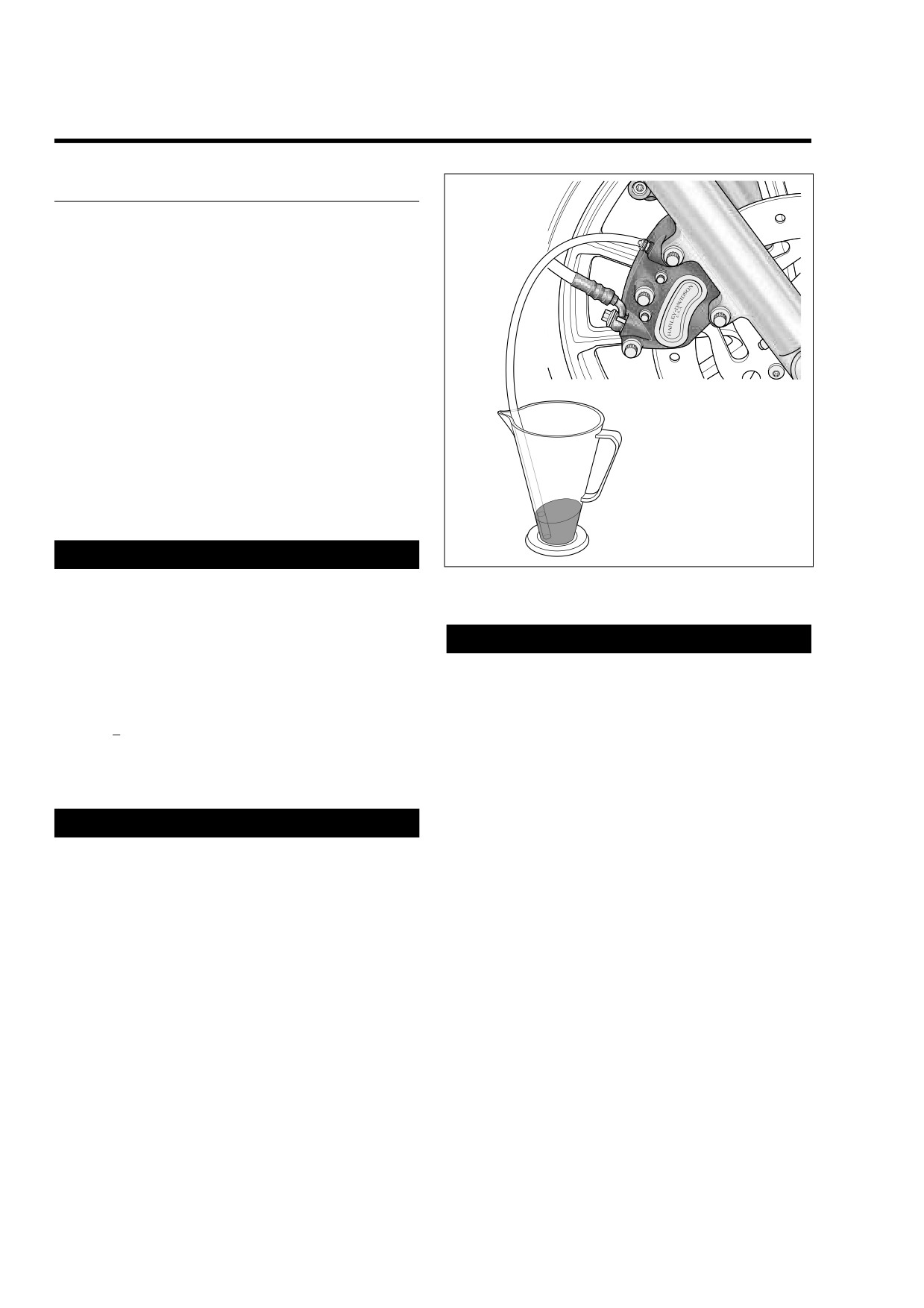
1.
Install end of a length of plastic tubing over caliper
8.
Add brake fluid to the master cylinder reservoir until the
bleeder valve. Place free end of tube in a clean con-
fluid level is about 1/4 inch (6.4 mm) from the top. Do not
tainer. See Figure 2-72. Stand motorcycle upright.
reuse brake fluid.
2-62
2006 Touring: Chassis
HOME
9.
Install the master cylinder reservoir cover, but first verify
that the cover gasket bellows is not extended or brake
1WARNING
fluid will be ejected from the reservoir. Install two Phillips
screws and alternately tighten to
6-8 in-lbs
(0.7-0.9
After repairing the brake system, test brakes at low
speed. If brakes are not operating properly, testing at
Nm).
high speeds can cause loss of control, which could
result in death or serious injury. (00289a)
10. Test ride motorcycle. Repeat the bleeding procedure if
brakes feel spongy.
2006 Touring: Chassis
2-63
HOME
FRONT FORKS
2.15
CHANGING FORK OIL
2
NOTE
If changing the fork oil at the 50,000 mile (80,000 km) service
interval, or if fork is leaking or fails visual inspection, see
REMOVAL and DISASSEMBLY, as complete disassembly
and inspection of the fork is required. However, if a decision
has been made to replace the fork oil before the recom-
mended service interval, and the fork passes visual inspec-
tion, see steps 1-5 below.
3
1.
Disassemble motorcycle and remove fork. See
REMOVAL.
2.
Partially disassemble fork. See DISASSEMBLY, steps 1-
8.
1
8312
3.
Position fork assembly upside down over drain pan.
Allow sufficient time for fork to thoroughly drain (about
1.
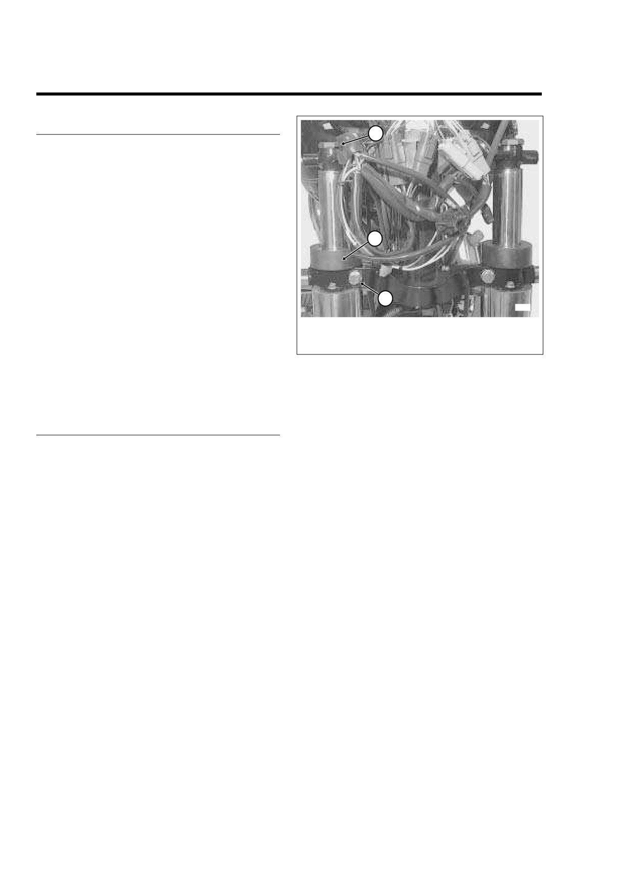
Pinch Bolt
10-15 minutes).
2.
Fork Cap Bolt
3.
Fork Stop
4.
Fill and assemble fork. See ASSEMBLY, steps 14-21.
Figure 2-73. Remove Fork Cap Bolt (FLHR/C/S Shown)
5.
Install fork and assemble motorcycle. See INSTALLA-
TION.
c. Remove two lower fork bracket screws to release
front turn signal lamp/auxiliary lamp bracket,
chrome skirt and inner fairing. If necessary, see
REMOVAL
Section
8.16 TURN SIGNAL LAMPS, FRONT
TURN SIGNAL LAMP, FLHX, REMOVAL, or Sec-
1.
Place suitable blocking under frame to raise front wheel
tion
8.13 AUXILIARY LAMPS, AUXILIARY LAMP
several inches off the floor. For best results, use an
BRACKET, REMOVAL.
hydraulic center stand on a level surface.
FLTR:
2.
Remove the front wheel and fender. See Section 2.33
a. Remove instrument nacelle. See Section
2.31
FRONT FENDER, REMOVAL.
UPPER FAIRING/WINDSHIELD (FLTR), INSTRU-
3.
Proceed as follows:
MENT NACELLE, REMOVAL.
FLHR/C/S:
4.
Standing at front of motorcycle, loosen fork cap bolt from
a. Remove headlamp nacelle. See Section
2.32
fork tube plug at top of fork tube, but do not remove.
WINDSHIELD/HEADLAMP NACELLE (FLHR/C/S),
5.
Loosen pinch bolt (with lockwasher) on left side of lower
NACELLE REMOVAL
(FLHR/C) or NACELLE
fork bracket, but do not remove. See Figure 2-73.
REMOVAL (FLHRS).
6.
Spray glass cleaner on fork tube above the rubber fork
stop. After lubricating surfaces, move fork stop up fork
FLHX, FLHT/C/U:
tube until it contacts bottom of upper fork bracket.
a. Loosen two outer fairing screws outboard of the
7.
Holding fork slider to prevent fork from dropping, remove
speakers on the left and right side. Remove two
fork cap bolt from fork tube plug. Slide fork tube down
outer fairing screws reaching in below the left and
and out of upper fork bracket, fork stop, lower fork
right sides of the fairing cap. If necessary, see Sec-
bracket, and slider cover.
tion
2.30 UPPER FAIRING/WINDSHIELD (FLHX,
8.
Thread fork cap bolt back into fork tube plug to prevent
FLHT/C/U), OUTER FAIRING/WINDSHIELD,
loss of fork oil while handling.
REMOVAL.
9.
Move front fork to bench area. Place suitable drain pan
b. Remove fairing cap. See Section
2.30 UPPER
on floor beneath vise.
FAIRING/WINDSHIELD (FLHX, FLHT/C/U), FAIR-
ING CAP, REMOVAL.
10.
Repeat steps 4-9 to remove right fork.
2-64
2006 Touring: Chassis
HOME
4.
Remove fork cap bolt from fork tube plug. Remove and
discard quad ring seal.
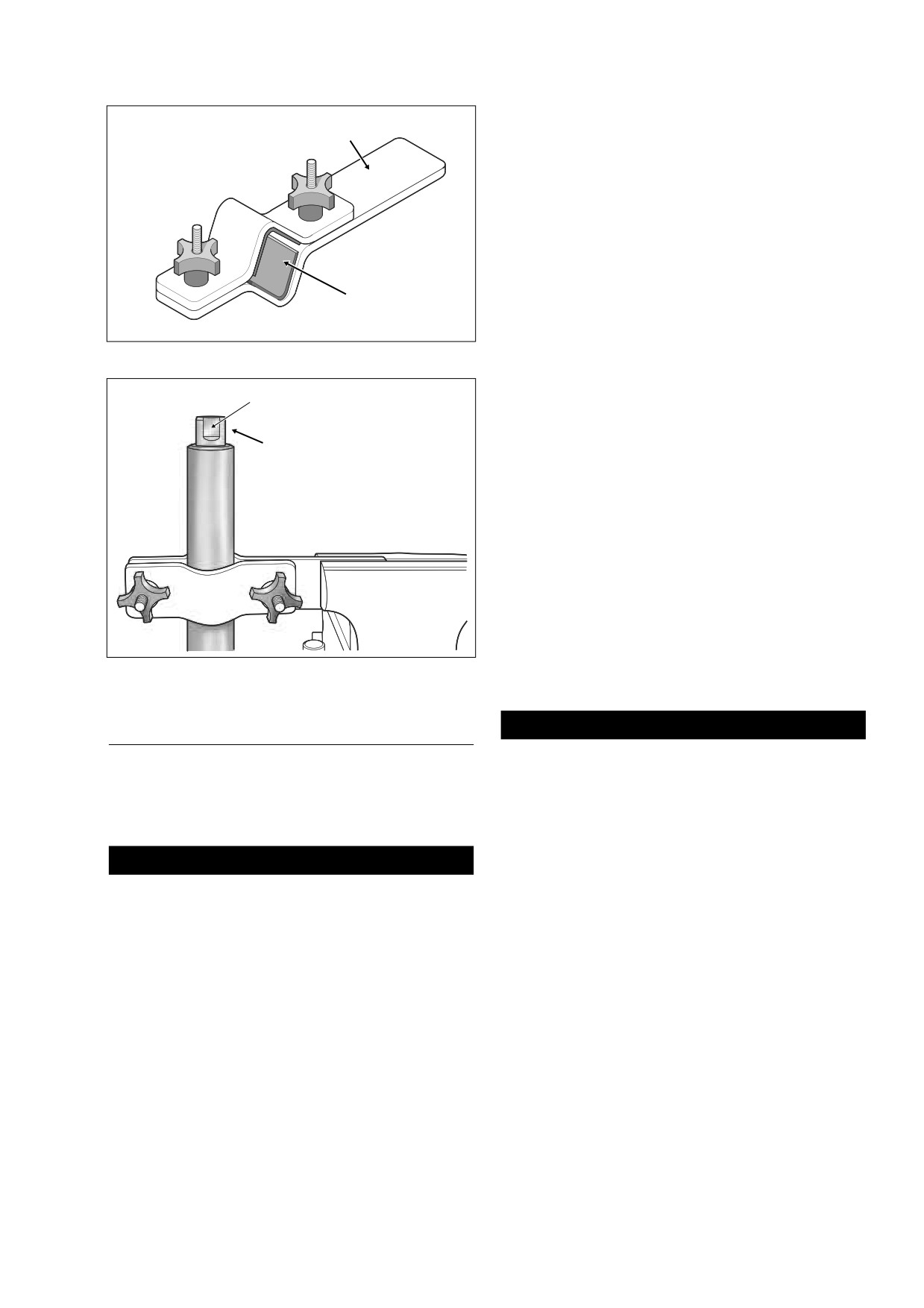
Vise Grip
5.
Using flat, slowly unthread fork tube plug from fork tube.
Be aware that fork tube plug is under spring pressure, so
have a firm grasp on plug as the last thread is turned.
Remove O-ring from fork tube plug. Discard O-ring.
6.
Remove fork spring from fork tube.
7.
Remove fork assembly from fork tube holder.
8.
Turning fork upside down, drain fork oil into drain pan.
Rubber Pad
For best results, slowly pump fork tube and slider at least
ten times. Be aware that damper valve, if equipped, may
fall out of inverted fork tube while draining. With the wear
ring at the bottom (spring side up), slide damper valve
Figure 2-74. Fork Tube Holder (HD-41177)
back into fork tube when drained.
Flat
NOTE
f1898x2x
If just changing the fork oil, continue procedure at ASSEM-
BLY, step 14. If overhauling the fork assembly, continue with
Fork Tube
Plug
step below.
9.
Install fork spring back into fork tube.
10. Place a shop rag on the floor, and turning fork assembly
upside down, press end of spring against rag. While
compressing spring to prevent rotation of damper tube,
remove 6mm screw from end of fork slider. Use an air
impact wrench for best results. Discard 6mm screw and
copper crush washer.
11. Remove fork spring, damper valve (if equipped) and
damper tube from fork tube.
12. Remove wear ring and rebound spring from damper
Figure 2-75. Install Fork Tube Into Fork Holder
tube. Remove wear ring from damper valve, if equipped.
DISASSEMBLY
CAUTION
Do not expand or stretch retaining clip to remove from
1.
Remove the fork assembly. See REMOVAL in this sec-
fork tube or clip may become bent or distorted.
tion.
2.
On right side fork, remove nuts, lockwashers, flat wash-
13. Using pick tool, remove retaining clip between fork slider
and fork tube.
ers and axle holder from studs at end of fork slider.
14. Remove fork tube from fork slider.
CAUTION
NOTE
Exercise caution to avoid scratching or nicking fork
To overcome any resistance, use the fork tube as a slide
tube. Damaging tube can result in fork oil leaks after
hammer, that is, first push fork tube into fork slider and then
assembly.
pull it outward with a moderate amount of force. Repeat this
sequence until fork tube separates from fork slider.
3.
Obtain the FORK TUBE HOLDER (HD-41177). See Fig-
ure 2-74. Proceed as follows:
15. Slide fork oil seal, slider spacer and slider bushing off
a. Clamp end of tool in vise in a horizontal position
end of fork tube. Discard fork oil seal and slider bushing.
with plastic knobs facing toward you.
16. Gently pry at split line to expand fork leg bushing, and
b. With the fork cap bolt topside, clamp fork tube
then remove from groove at end of fork tube. Discard
between rubber pads on inboard side of tool.
fork leg bushing.
Tighten knobs until fork tube is securely held. See
Figure 2-75.
17. Remove lower stop from fork slider.
2006 Touring: Chassis
2-65
HOME
3.
With the wear ring topside, slide damper tube into fork
tube, so that tube end drops through hole at bottom of
f2045x2x
fork tube. Install lower stop at end of damper tube.
4.
Install fork slider in fork tube holder. Slide fork tube into
fork slider.
5.
Coat slider bushing ID with clean fork oil. Slide slider
bushing down fork tube.
6.
Slide slider spacer down fork tube until it contacts slider
bushing.
7.
Obtain the FORK OIL SEAL INSTALLER (HD-34634).
See Figure 2-77. Proceed as follows:
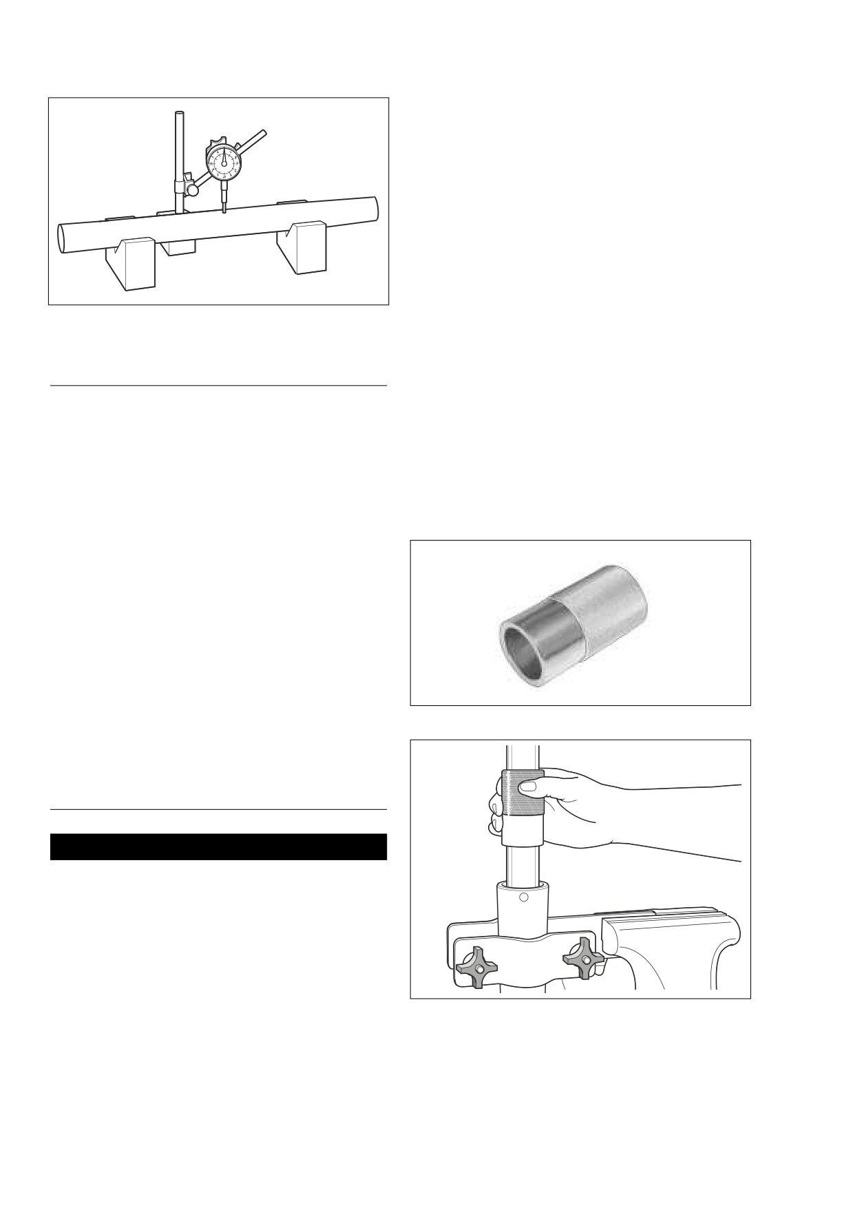
Figure 2-76. Measure Fork Tube Runout
a. Slide the fork oil seal installer down the fork tube,
and using the tool like a slide hammer, drive slider
bushing into counterbore of fork slider. Remove tool.
CLEANING AND INSPECTION
NOTE
Place masking tape over edge of fork tube to avoid damaging
1.
Thoroughly clean and inspect all parts. Replace any
lip of fork oil seal during installation.
parts that are bent, broken or obviously damaged.
b. Coat new fork oil seal ID with clean fork oil. With the
2.
Inspect fork cap bolt quad ring seal and fork tube plug O-
lip garter spring side facing down (toward the fork
ring for cuts, tears or signs of deterioration. Replace if
slider), slide seal down fork tube until it contacts
necessary.
slider spacer. Remove masking tape from edge of
fork tube.
3.
Replace the retaining clip if bent or distorted.
4.
Check the slider and fork leg bushings for scratches or
excessive wear. Always replace bushings in a set if
f1901x2x
either bushing is damaged or worn.
5.
Check the fork tube and slider for scoring, scratches and
excessive or abnormal wear. Replace parts as neces-
sary. Set the fork tube on V-blocks and measure the
runout using a dial indicator gauge. Replace fork if
runout exceeds 0.008 inch (0.2 mm). See Figure 2-76.
6.
Inspect upper fork spring and rebound spring for dam-
age or distortion. Replace upper fork spring if free length
is less than 18.4 inches (467.3 mm). Replace rebound
Figure 2-77. Fork Oil Seal Installer (HD-34634)
spring if free length is less than 15/16 inches (23.8 mm)
or whenever the upper fork spring requires replacement.
f1902x2x
ASSEMBLY
CAUTION
Exercise caution to avoid scratching or nicking fork
tube. Damaging tubes can result in fork oil leaks after
assembly.
1.
Coat fork leg bushing ID with clean fork oil. Expand fork
leg bushing at split line only so far as required to slip
over end and into groove of fork tube.
2.
Install new wear ring in groove at top of damper tube.
Install rebound spring on opposite end.
Figure 2-78. Install Fork Oil Seal
2-66
2006 Touring: Chassis
HOME
c. Slide the fork oil seal installer down the fork tube
until it contacts the fork oil seal.
d. Using the tool like a slide hammer, drive fork oil seal
down fork tube until retaining clip groove is visible in
fork slider ID. See Figure 2-78. Remove tool.
CAUTION
Do not expand or stretch retaining clip to install on fork
tube or clip may become bent or distorted.
e. Slide the retaining clip down the fork tube until it
contacts the fork oil seal. Install retaining clip in the
fork slider groove.
Figure 2-79. Front Fork Oil Level Gauge (HD-59000B)
8.
Install fork spring into fork tube.
f2168x2x
9.
Remove fork assembly from fork tube holder.
10. Place a shop rag on the floor, and turning fork assembly
upside down, press end of spring against rag.
11. Install new 6mm screw with copper crush washer. Slide
screw through hole at bottom of fork slider and start into
end of damper tube.
12. While compressing spring to prevent rotation of damper
tube, tighten 6mm screw to 132-216 in-lbs (14.9-24.4
Nm).
13. Remove fork spring from fork tube.
14. With the fork tube topside, clamp fork slider (not the fork
tube) into fork tube holder.
15. Install the drain plug at the bottom of the fork slider, if
removed. Tighten plug to 72-96 in-lbs (8-11 Nm).
Figure 2-80. Remove Excess Fork Oil
NOTE
All touring models with the exception of Road King have the
damper valve type fork on both the left and right sides. Road
Table 2-5. Fork Oil Requirements
King uses the conventional type fork on both sides. See step
AMOUNT
16 to set fork oil level on a damper valve type fork; see step
FORK
MODEL
17 to set fork oil level on a conventional type fork.
TYPE
OZ.
ML
IN.
MM
16. Set fork oil level on damper valve type fork as follows:
All models except
Damper Valve
10.8
319
5.59
142
Road King
Damper Valve Type Fork: FLHX, FLHT/C/U, FLTR
Road King
Conventional
11.1
328
5.24
133
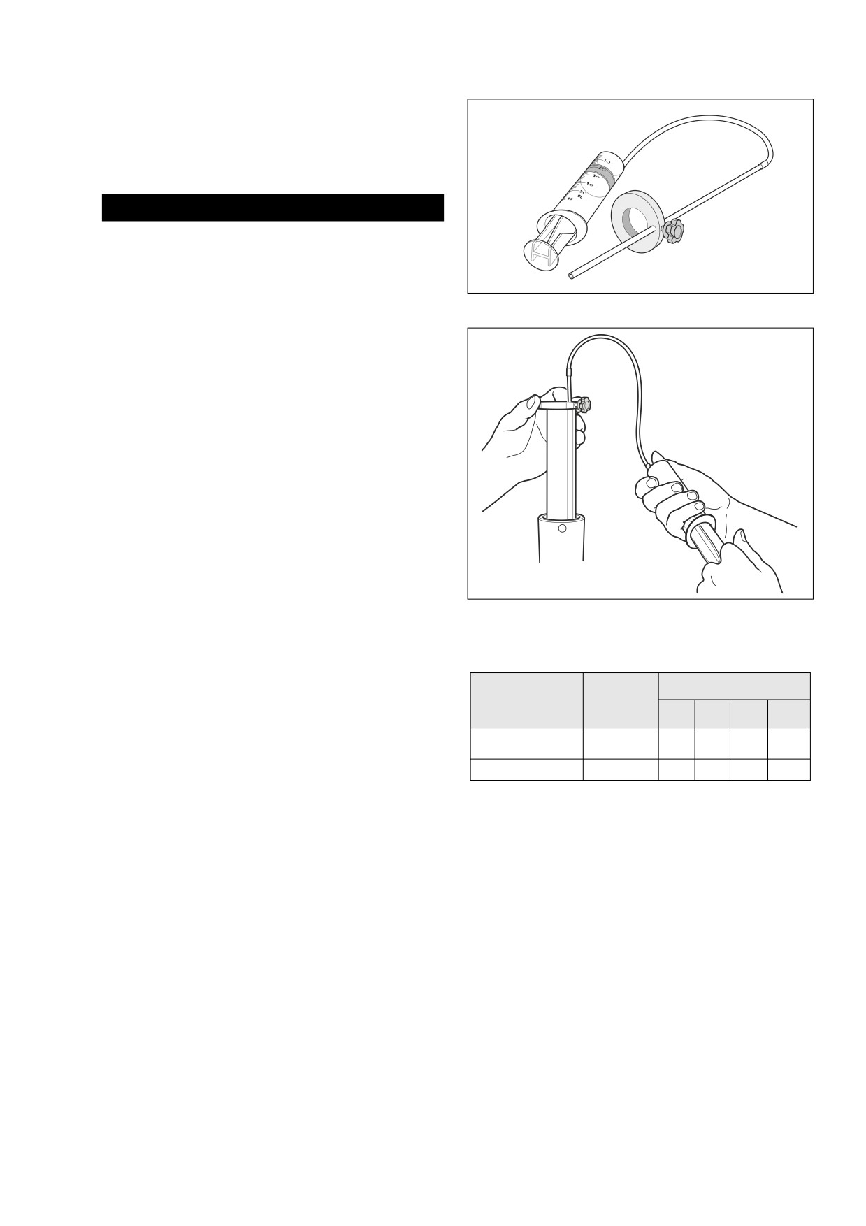
a. Pour slightly more than 10.8 ounces (319 ml) of
Harley-Davidson Type E Fork Oil directly into the
g. Loosen thumbscrew on metal ring of tool and move
fork tube.
it up or down the rod until bottom of ring is 5.59
b. Slowly pump fork tube until some resistance is felt
inches (142 mm) from end of rod. Tighten thumb-
and then pump a few more times.
screw.
c. Install new wear ring in groove of damper valve.
h. Push the plunger on the cylinder all the way in.
With the wear ring at the bottom (spring side up),
slide damper valve into fork tube.
i.
With the fork tube bottomed in the fork slider, insert
d. Install fork spring into fork tube. Use fork spring to
rod until metal ring rests flat on top of fork tube. See
push damper valve to bottom of fork tube. Remove
Figure 2-80.
fork spring from fork tube.
j.
Pull out plunger to suck fork oil from fork tube.
e. Slowly pump fork tube a few more times to dis-
Observe fork oil through transparent tube as it is
charge air from damper valve.
drawn into cylinder. If no oil is drawn through trans-
parent tube, add enough oil so that tool usage sets
f.
See Figure 2-79. Obtain the FRONT FORK OIL
fork oil level.
LEVEL GAUGE (HD-59000B).
2006 Touring: Chassis
2-67
HOME
k. Remove rod from fork tube. Push plunger into cylin-
der to eject excess fork oil into suitable container.
1
f2394x2x
2
l.
If necessary, repeat steps 16(i) thru 16(k). Level is
correct when no fork oil is observed being drawn
through transparent tube.
3
4
* Fairing Equipped
Motorcycles Only
1WARNING
Be sure fork oil level is correct. The incorrect amount of
fork oil can adversely affect handling and may lead to
loss of vehicle control, which could result in death or
serious injury.
5
17.
Set fork oil level on conventional type fork as follows:
Conventional Type Fork: FLHR/C/S
a. Pour slightly more than 11.1 ounces (328 ml) of
6
12
Harley-Davidson Type E Fork Oil directly into the
7
fork tube.
13
b. Slowly pump fork tube until some resistance is felt
8
and then pump a few more times.
14
c. See Figure 2-79. Obtain the FRONT FORK OIL
15
LEVEL GAUGE (HD-59000B).
9
16
d. Loosen thumbscrew on metal ring of tool and move
it up or down the rod until the bottom of ring is 5.24
inches (133 mm) from end of rod. Tighten thumb-
10
17
screw.
e. Push the plunger on the cylinder all the way in.
f.
With the fork tube bottomed in the fork slider, insert
rod until metal ring rests flat on top of fork tube. See
18
Figure 2-80.
19
g. Pull out plunger to suck fork oil from fork tube.
Observe fork oil through transparent tube as it is
drawn into cylinder. If no oil is drawn through trans-
11
parent tube, add enough oil so that tool usage sets
fork oil level.
20
23
h. Remove rod from fork tube. Push plunger into cylin-
der to eject excess fork oil into suitable container.
i.
If necessary, repeat steps 17(f) thru 17(h). Level is
21
24
correct when no fork oil is observed being drawn
25
through transparent tube.
22
26
1WARNING
1.
Fork cap bolt
14.
Slider spacer
Be sure fork oil level is correct. The incorrect amount of
2.
Quad ring seal
15.
Slider bushing
fork oil can adversely affect handling and may lead to
3.
Fork tube plug
16.
Fork leg bushing
loss of vehicle control, which could result in death or
4.
O-Ring
17.
Lower stop
serious injury.
5.
Spring
18.
Fork slider
6.
Damper valve*
19.
Plug
18. With the closer spaced coils at the bottom, slide fork
7.
Wear ring*
20.
Flat Washer
spring into fork tube.
8.
Wear ring
21.
Copper washer
19. Remove fork slider from fork tube holder. Clamp fork
9.
Damper tube
22.
Screw (6mm)
tube into fork tube holder.
10. Rebound spring
23.
Axle holder
20. Install new O-ring onto fork tube plug. Compressing fork
11. Fork tube
24.
Flat washer (2)
spring with end of fork tube plug, thread fork tube plug
12. Retaining clip
25.
Lockwasher (2)
into fork tube. Tighten fork tube plug to 22-58 ft-lbs (30-
13. Lip seal
26.
Nut (2)
79 Nm).
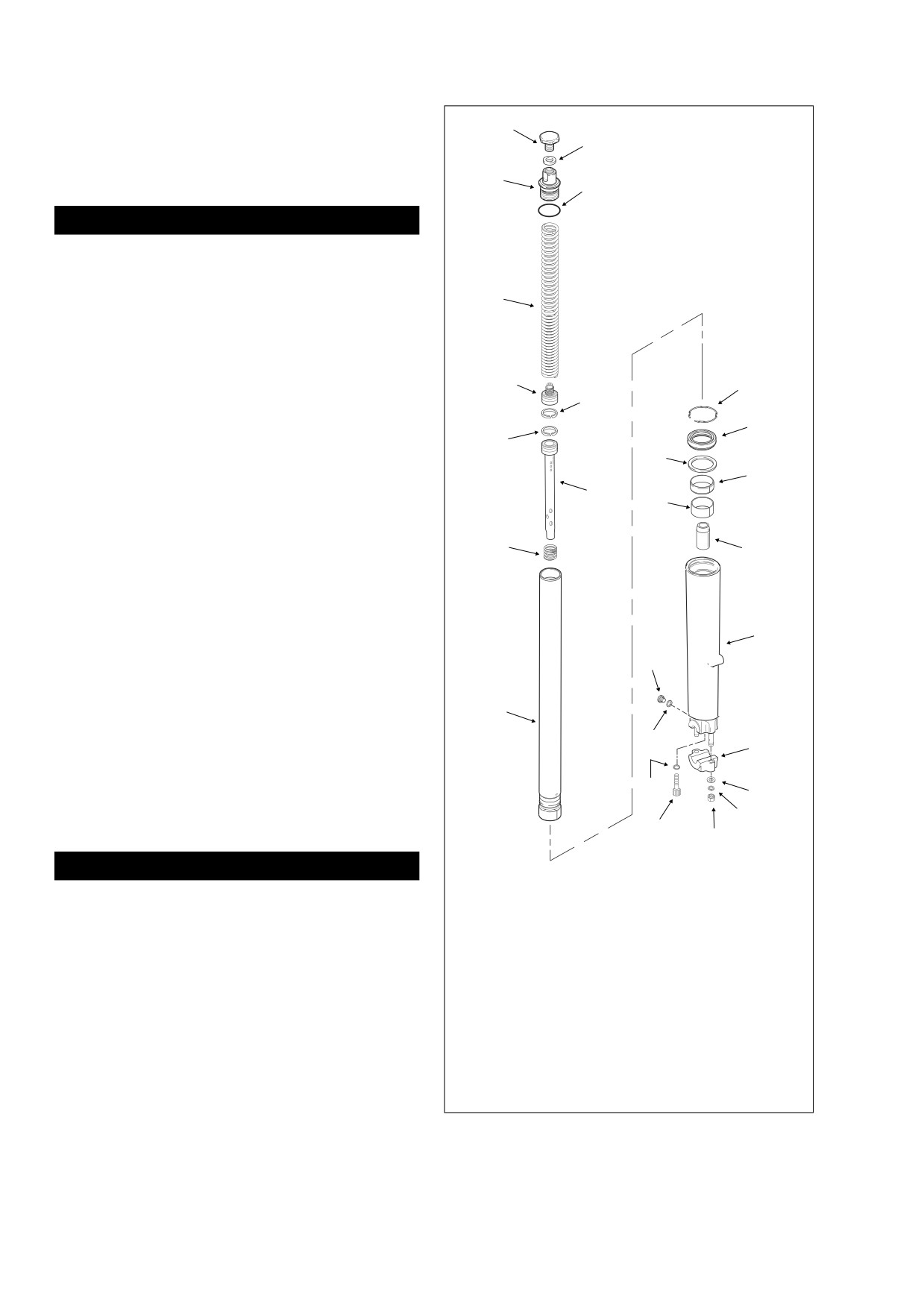
Figure 2-81. Right Side Fork
2-68
2006 Touring: Chassis
HOME
21. Install new quad ring seal onto fork cap bolt. Thread fork
FLHX, FLHT/C/U:
cap bolt into fork tube plug to prevent loss of fork oil
a. Slide chrome skirt into position between the inner
while handling.
fairing and the front turn signal lamp/auxiliary lamp
22. On right side fork, loosely install axle holder, flat wash-
bracket. Install two screws to fasten auxiliary lamp/
ers, lockwashers and nuts on studs at end of fork slider.
front turn signal lamp bracket, chrome skirt and
inner fairing to lower fork bracket. If necessary, see
Section
8.16 TURN SIGNAL LAMPS, FRONT
TURN SIGNAL LAMP, FLHX, INSTALLATION, or
INSTALLATION
Section
8.13 AUXILIARY LAMPS, AUXILIARY
LAMP BRACKET, INSTALLATION.
1.
Remove fork cap bolt.
b. Install fairing cap. See Section 2.30 UPPER FAIR-
ING/WINDSHIELD
(FLHX, FLHT/C/U), FAIRING
2.
Standing at front of motorcycle, slide fork tube up and
CAP, INSTALLATION.
into slider cover, lower fork bracket, fork stop, and upper
fork bracket. Install fork cap bolt.
c. Install two outer fairing screws reaching in below the
3.
Move rubber fork stop down fork tube until it contacts top
left and right sides of the fairing cap. Tighten two
of lower fork bracket. Lubricate surfaces with glass
outer fairing screws outboard of the speakers on the
cleaner, if necessary.
left and right side. If necessary, see Section 2.30
UPPER FAIRING/WINDSHIELD (FLHX, FLHT/C/
4.
Install pinch bolt (with lockwasher) on left side of lower
U), OUTER FAIRING/WINDSHIELD, INSTALLA-
fork bracket. See Figure 2-73. Tighten pinch bolt to 30-
TION.
35 ft-lbs (41-48 Nm).
5.
Tighten fork cap bolt to 50-60 ft-lbs (68-81 Nm).
FLTR:
6.
Repeat steps 1-5 on other fork, if removed.
a. Install instrument nacelle. See Section 2.31 UPPER
7.
Install the front fender and wheel. See Section 2.33
FAIRING/WINDSHIELD
(FLTR), INSTRUMENT
FRONT FENDER, INSTALLATION.
NACELLE, INSTALLATION.
8.
Proceed as follows:
FLHR/C/S:
a. Install headlamp nacelle. See Section 2.32 WIND-
SHIELD/HEADLAMP NACELLE
(FLHR/C/S),
NACELLE INSTALLATION (FLHR/C) or NACELLE
INSTALLATION (FLHRS).
2006 Touring: Chassis
2-69
HOME
LOWER FORK BRACKET COVER/AIR DAM
2.16
LOWER FORK BRACKET COVER
(FLHRS)
REMOVAL
1.
Moving to the back of the lower fork bracket, remove two
hex screws (with flat washers) to release cover flange.
2.
Holding cover to prevent from dropping, remove T40
TORX screw at bottom.
7590
INSTALLATION
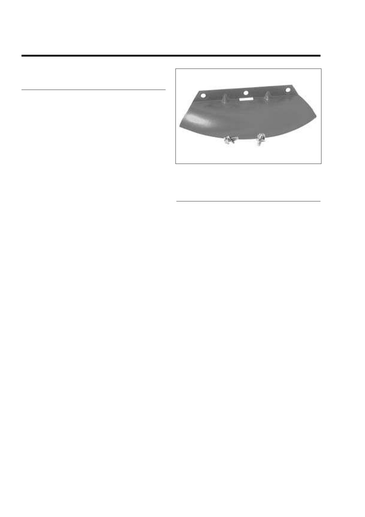
Figure 2-82. Air Dam
1.
With the concave side up, align holes in cover flange
with holes at back of the lower fork bracket. Start two hex
screws (with flat washers).
AIR DAM (FLTR)
NOTE
REMOVAL
Plastic plug(s) at back of lower fork bracket will prevent
proper cover installation. Remove and discard plug(s), if
NOTE
present.
By allowing the flow of air to pass under the fuel tank and
over the cylinder heads, removing the air dam evacuates
3.
Start T40 TORX screw at bottom of cover engaging off-
heated air and provides some relief to the rider in warmer
set hole in front brake line bracket.
temperatures (70˚ F. or above).
4.
Alternately tighten two hex screws to 70-110 in-lbs (7.9-
1.
Moving to the back of the lower fork bracket, remove two
12.4 Nm).
hex screws (with flat washers) to release air dam. See
5.
Tighten T40 TORX screw to 120-180 in-lbs (13.6-20.3
Figure 2-82.
Nm).
2.
Reinstall two hex screws (with flat washers) to keep dirt
and debris out of holes in lower fork bracket. Tighten
6.
Verify that cover does not contact brake lines to front
screws to 120-144 in-lbs (13.6-16.3 Nm).
brake calipers or master cylinder reservoir. Adjust either
brake line bracket or cover if necessary.
INSTALLATION
NOTE
Reinstall air dam in colder weather.
1.
With the concave side down, align holes in air dam with
holes at back of the lower fork bracket. Start two hex
screws (with flat washers).
NOTE
Plastic plug(s) at back of lower fork bracket will prevent
proper cover installation. Remove and discard plug(s), if
present.
2.
Alternately tighten hex screws to 120-144 in-lbs (13.6-
16.3 Nm).
2-70
2006 Touring: Chassis
HOME
STEERING HEAD BEARINGS
2.17
LUBRICATION
f2108x2x
At the 1000 mile (1600 km) service interval, and at every
10,000 mile (16,000 km) service interval thereafter, grease
the steering head bearings using Special Purpose Grease,
Part No. 99857-97. Turn handlebar full right to access the
grease fitting at the left side of the steering head. Connect
grease gun to fitting and inject grease until it exudes from top
and bottom of steering head. See Figure 2-83.
At every 25,000 mile (40,000 km) service interval, check the
swing-by following the CHECKING procedure below.
At every 50,000 mile (80,000 km) service interval, disassem-
ble the steering head and inspect the bearings for brinelling,
scoring, or other damage. Replace and/or repack the bear-
ings as required.
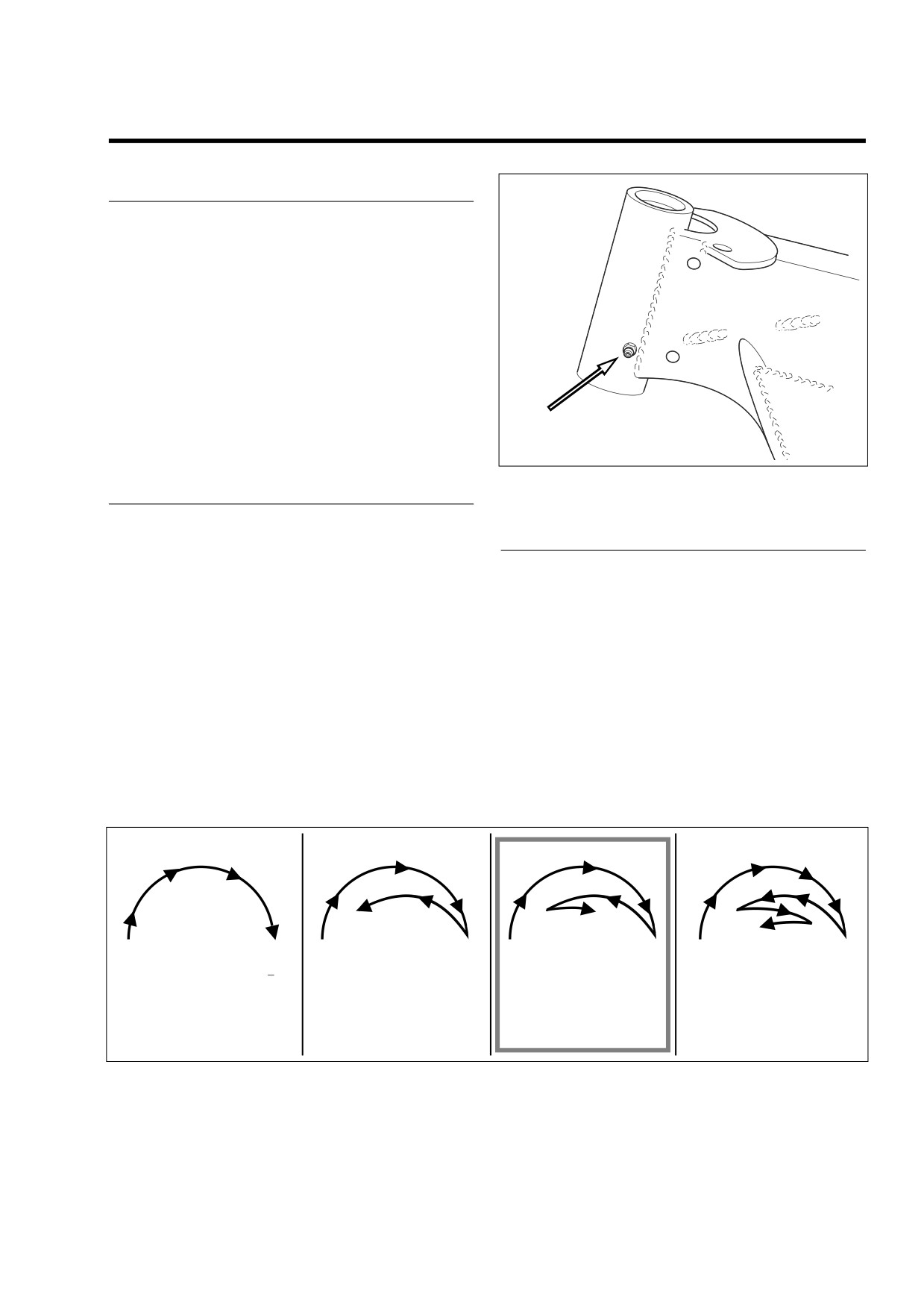
Figure 2-83. Steering Head Bearing Grease Fitting
CHECKING
1.
Using an hydraulic center stand on a level surface, raise
ADJUSTMENT
the vehicle so that the front and rear tires are the same
distance from the floor.
1.
On FLHX, FLHT/C/U models, remove outer fairing and
2.
Verify that motorcycle is in stock configuration. Remove
radio (storage box on FLHT). On FLHR/C/S, remove
all non-factory accessories, since they can influence
headlamp nacelle. On FLTR models, remove the instru-
front end swing momentum (and lead to improper adjust-
ment bezel.
ment).
2.
Loosen the pinch bolts on the lower fork bracket and
3.
Turn the front wheel until contact is made with the left
slide the rubber fork stops up slightly on the fork tubes.
fork stop and then let go. The wheel should swing right,
This will prevent any binding of the front end when the
left, then right and stop. The wheel need not stop near
adjustment is made. See Figure 2-73.
the center or straight-forward position, but it must move
to the right making a partial third swing. See frame C of
3.
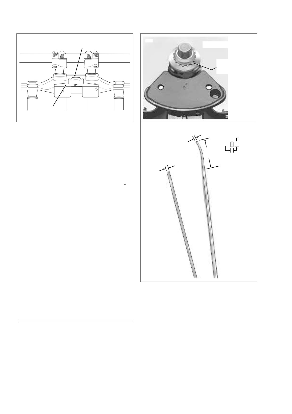
Bend tab on lock plate away from flat of fork stem nut.
Figure 2-84.
Loosen the fork stem nut. See Figure 2-85.
4.
To correct a swing pattern that is too short or too long,
4.
Fashion a bearing adjuster tool using a drill rod
16
see ADJUSTMENT below.
inches long. See lower frame of Figure 2-86.
A
B
C
D
Steering head is set up too
Steering head is still set up too
Steering head adjustment is
Steering head is set up too
tight. The wheel stops in its first
tight. The wheel stops in its
OK. The wheel need not stop
loose. The wheel begins its
swing.
second swing. A steering head
near the center, but it must
fourth swing. A steering head
that is too tight can interfere
move to the right making a
that is too loose can interfere
with the vehicle’s ability to
partial third swing.
with the vehicle’s ability to
absorb a weave.
absorb a wobble.
CORRECT
f1475x2x
Figure 2-84. Check Steering Head Bearing Swing-By
2006 Touring: Chassis
2-71
HOME
f1907x2x
Fork Stem
9441
Nut
Upper Fork Bracket
Bearing
Adjuster
Star Nut
Lock
Plate
Figure 2-85. Fork Stem Nut
f1792x2x
5/32 Inch goes back
for 1-1/4 Inches.
To decrease the number of swings, stand on the left side
5/32 Inch
A
of the vehicle and insert the rod to engage the notches
1/8 Inch
of the bearing adjuster (star) nut under the fork bracket.
NOTE
2 Inches
Each Rod is 1/4 Inch Diameter
Start of
Push forward to rotate the nut clockwise.
by 16 Inches Long.
Bend
A
End View
NOTE
Turning the bearing adjuster nut as little as one notch will
A
make a noticeable difference in the swing pattern.
To increase the number of swings, stand on the right
side of the vehicle and insert the rod to engage the
notches of the bearing adjuster nut. Push forward to
rotate the nut counterclockwise.
5.
Tighten the fork stem nut to 60-80 ft-lbs (81-109 Nm).
The tightness of the nut will affect the swing pattern.
6.
Recheck the swing pattern. See step 3 under CHECK-
ING. Repeat steps 4-6 above until swing pattern is cor-
rect.
7.
Tighten pinch bolts to 30-35 ft-lbs (41-48 Nm) and prop-
erly position the rubber fork stops.
8.
Verify that the fork stem nut is tightened to 60-80 ft-lbs
FLTR
(81-109 Nm). Bend tab on lockplate against flat of fork
All Others
Road Glide
stem nut.
9.
On FLHX, FLHT/C/U models, install radio (storage box
on FLHT) and outer fairing. On FLHR/C/S, install head-
lamp nacelle. On FLTR models, install the instrument
bezel.
Figure 2-86. Fashion Steering Head Bearing
10. Recheck the swing pattern. See step 3 under CHECK-
Adjustment Tool From Drill Rod
ING. Repeat ADJUSTMENT procedure if swing pattern
is not correct.
2.
Remove the front wheel and fork assemblies. Remove
brake line from lower fork bracket.
REMOVAL
3.
Bend tab away from flat of fork stem nut. Remove nut.
1.
On FLHX, FLHT/C/U models, remove the auxiliary lamp
4.
Remove the bearing adjuster and fork stem assembly.
bracket, outer fairing and radio (storage box on FLHT).
See upper frame of Figure 2-86. Remove dust shield
On FLHR/ C, remove headlamp nacelle. On FLTR mod-
and bearing from top of steering head.
els, remove the instrument nacelle.
2-72
2006 Touring: Chassis
HOME
f1279x2x
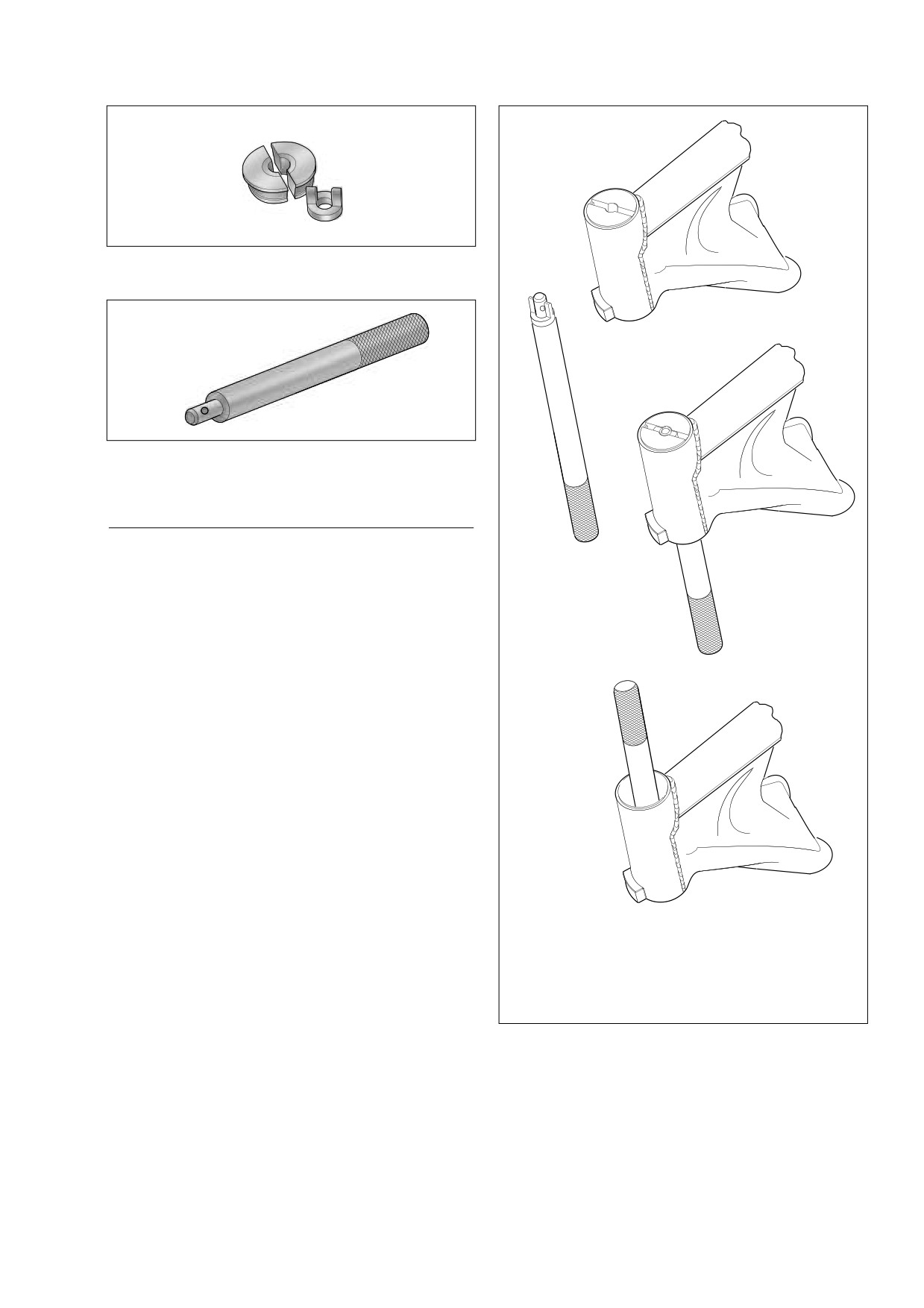
Remover
Collet
A
Figure 2-87. Steering Head Bearing Race Remover
(Part No. HD-39301A)
B
Figure 2-88. Universal Driver (Part No. HD-33416)
INSPECTION
1.
Check the bearing races in the steering head. If pitted or
C
grooved, replace both the bearings and races.
2.
Turn bearings in races. Replace the bearings if they do
not move freely and smoothly. Always replace both races
and bearings even if one race and bearing appears
good.
STEERING HEAD BEARING RACE REMOVAL
NOTE
To remove the upper and lower steering head bearing races,
use the Steering Head Bearing Race Remover (Part No. HD-
39301A) with the Universal Driver (Part No. HD-33416). See
D
Figure 2-87 and Figure 2-88.
Proceed as follows:
1.
With the tapered side down, seat the two-piece remover
tool on the upper bearing race leaving a gap in the mid-
dle. See Figure 2-89.
2.
Install the collet on the driver.
3.
Insert the driver at the bottom of the steering head tube,
and while holding the remover tool on the race, center
the collet in the gap. Tap the driver to remove the upper
A
Install Remover on Upper Race
race.
B
Install Collet on Driver
C
Install Driver in Remover and Remove Upper Race
4.
Reverse the tool and repeat the procedure to remove the
D
Remove Lower Race
lower bearing race.
Figure 2-89. Remove Upper and Lower
REMOVING BEARING FROM FORK STEM
Steering Head Bearing Races
1.
Chisel cage retaining rollers off bearing on fork stem.
2006 Touring: Chassis
2-73
HOME
2.
Turn the stem upside down while heating the inner race.
Race will expand and fall free.
1WARNING
Be sure fork stem nut adjustment is correct. An improp-
erly adjusted nut can adversely affect handling and may
ASSEMBLY
lead to loss of vehicle control, which could result in
death or serious injury.
1.
Pack new bearings with Harley-Davidson SPECIAL
2.
Install upper fork bracket and fork stem nut. Tighten nut
PURPOSE GREASE, Part No. 99857-97.
to
60-80 ft-lbs
(81-109 Nm). Bend the lockplate tab
2.
Install dust shield on fork stem. Use a sleeve that will
against the nut flat. See Figure 2-85.
contact only the inner race of the new bearing, then
press the bearing into place on fork stem.
3.
Install fork assemblies, radio (storage box on FLHT),
outer fairing and auxiliary lamp bracket. On FLHR/C/S,
3.
Install new bearing races in steering head using STEER-
install headlamp nacelle. On FLTR models, install the
ING HEAD BEARING RACE INSTALLATION TOOL,
instrument bezel.
Part No. HD-39302.
4.
Install the front wheel and bleed the front brake. Check
swing-by under CHECKING in this section.
INSTALLATION
1.
Install the fork stem assembly into the steering head.
Install the bearings and dust shield. Install the bearing
adjuster nut. Snug the adjuster nut down until bearing
play is taken up and the fork stem turns freely. Overtight-
ening the nut will cause excessive bearing wear.
2-74
2006 Touring: Chassis
HOME
REAR AIR SUSPENSION
2.18
GENERAL
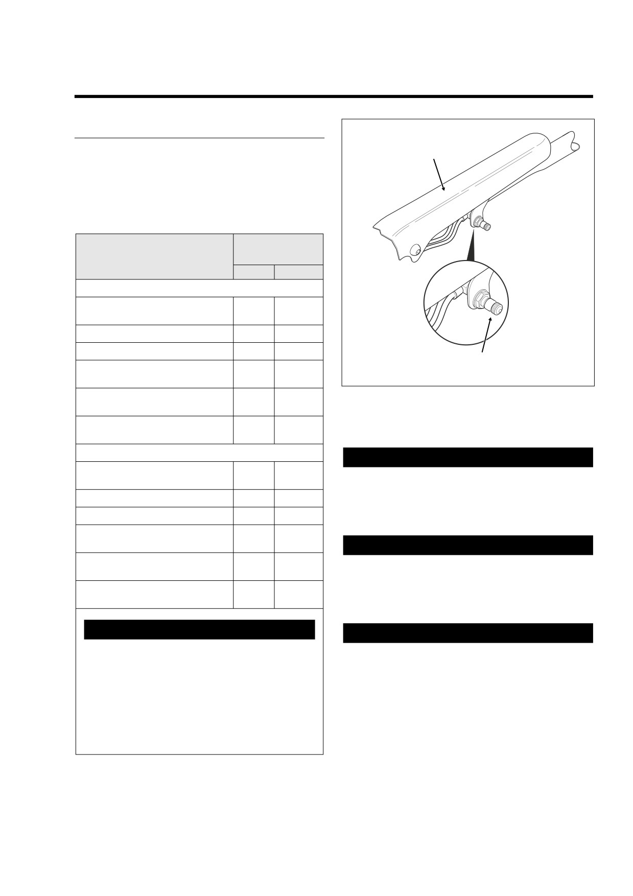
Frame
All models feature air-adjustable rear suspension. Air pres-
Cover
sure may be varied to suit load conditions, riding style and
personal comfort. Less initial pressure does not necessarily
result in a softer ride. See the table below for the recom-
mended air suspension pressures.
Table 2-6. Rear Air Suspension Pressures
Recommended
Shock Loading
Pressures
PSI
kPa
All Models Except FLHRS, FLHX - Standard Shocks
Solo rider up to 150 lbs. (68 kg),
0
0
hereafter referred to as “Average”
Solo rider 150-200 lbs. (68-91 kg)
0-10
0-69
Solo rider 200-250 lbs. (91-113 kg)
5-15
35-103
Air Valve
Average rider with passenger
f2018x2x
10-15
69-103
up to 150 lbs. (68 kg)
Average rider with passenger
Figure 2-90. Rear Air Suspension Air Valve
20-25
138-172
up to 200 lbs. (91 kg)
(Under Protective Cap)
Maximum GVWR
20-35
138-241
(see Section 2.1 Specifications)
FLHRS, FLHX Only - Low Profile Shocks
CAUTION
Solo rider up to 160 lbs. (73 kg),
0-5
0-35
hereafter referred to as “Average”
Improper inflation of rear air suspension components
also can result in a reduction of available suspension
Solo rider 160-200 lbs. (73-91 kg)
0-10
0-69
travel, reduced rider comfort and possible damage to
Solo rider over 200 lbs. (91 kg)
5-10
35-69
shock absorbers.
Average rider with passenger
20-30
138-207
up to 150 lbs. (68 kg)
CAUTION
Average rider with passenger
25-35
172-241
All air components fill rapidly. Use low air line pressure
over 150 lbs. (68 kg)
to avoid possible damage. A small hand or foot operated
Maximum GVWR
air pump is the best way to add air to suspension com-
40-50
276-345
(see Section 2.1 Specifications)
ponents.
1WARNING
CAUTION
Use this table as a starting point in determining suit-
Use a no-loss air gauge to check air pressure. Check
able rear air suspension pressures. Do not exceed
pressure in shocks weekly if in daily use or before each
maximum GVWR when loading vehicle and do not
trip if only used occasionally.
pressurize system in excess of 50 psi (345 kPa) for
FLHRS, FLHX models and 35 psi (241 kPa) for all
others. Excessive load weight and/or air suspension
NOTE
pressure can adversely affect handling and lead to
An AIR SUSPENSION PUMP AND GAUGE (Part No. HD-
loss of vehicle control, which could result in death
34633A) is available at your Harley-Davidson dealer.
or serious injury.
2006 Touring: Chassis
2-75