Harley Davidson FLHRC 2006. Maintenance & Repair Manual - page 2
HOME
TRANSMISSION LUBRICANT
1.9
GENERAL
8496
See Section
1.2 MAINTENANCE SCHEDULE for the
required service interval.
PROCEDURE
1.
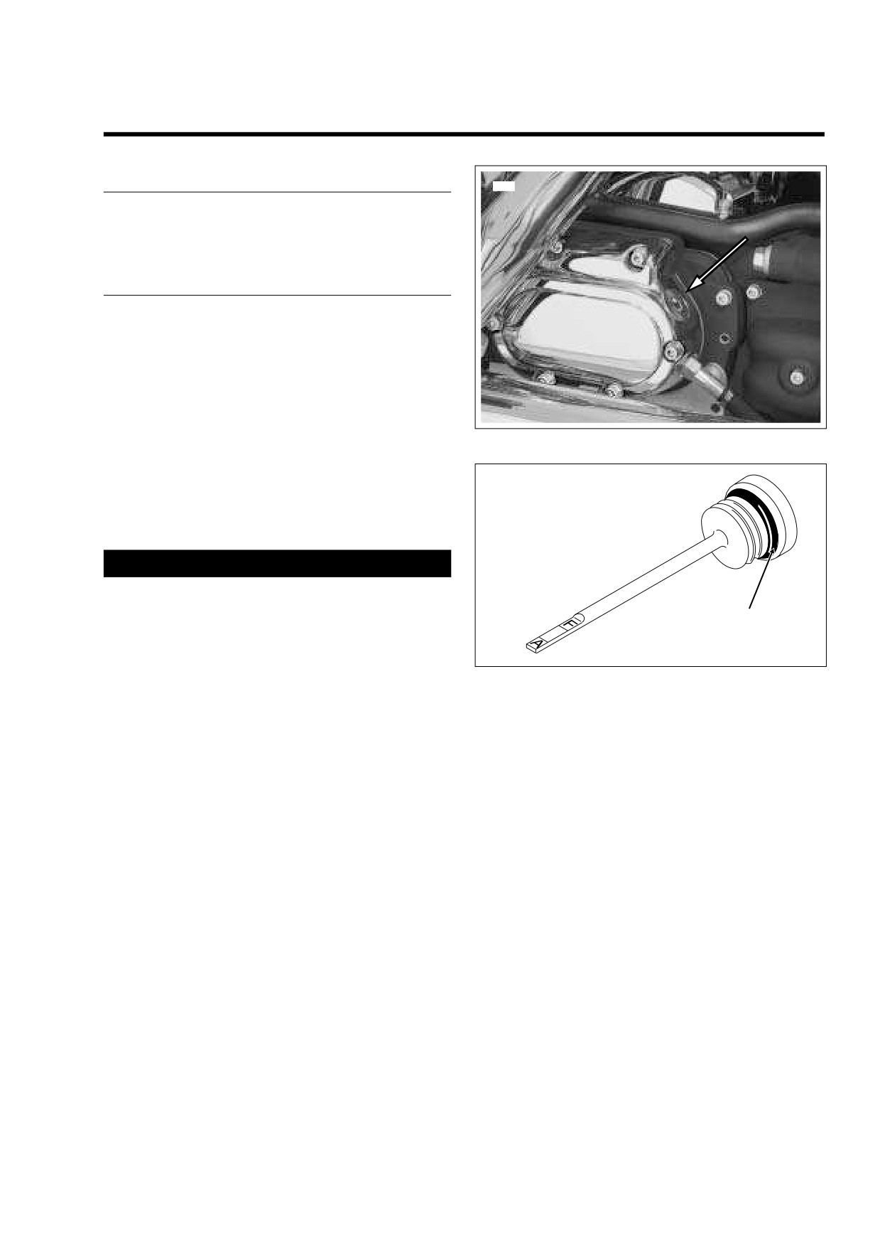
Remove the filler plug from the clutch release cover on
the right side of the transmission case. See Figure 1-11.
Check the O-ring for tears, cuts or general deterioration.
Replace as necessary. See Figure 1-12.
2.
Locate transmission drain plug on the right side of the oil
pan. Remove the magnetic plug and drain the transmis-
sion lubricant into a suitable container.
Figure 1-11. Clutch Release Cover
3.
Remove any foreign material from the drain plug. Check
the O-ring on the drain plug for tears, cuts or general
deterioration. Replace as necessary.
OMF50
4.
Install the transmission lubricant drain plug and tighten
to 14-21 ft-lbs (19-28 Nm).
1WARNING
When adding lubricant, do not allow dirt, debris or other
contaminants to enter the transmission case. Exercise
O-Ring
caution so that lubricant does not contact rear wheel,
tire and brake components. Such contact can adversely
affect traction and may lead to loss of vehicle control,
which could result in death or serious injury.
Figure 1-12. Transmission Lubricant Filler Plug/Dipstick
5.
Fill the transmission with
20-24 oz. (590-710 ml) of
transmission lubricant or until the lubricant level on the
dipstick of the filler plug is at the F(ULL) mark with the
motorcycle in a level, upright position and the filler plug
resting on the threads.
Use only Harley-Davidson FORMULA+ TRANSMIS-
SION AND PRIMARY CHAINCASE LUBRICANT, Part
No. 99851-05 (quart).
6.
Install the transmission filler plug/dipstick in the clutch
release cover. Tighten the plug to 25-75 in-lbs (2.8-8.5
Nm).
2006 Touring: Maintenance
1-19
HOME
DRIVE BELT
1.10
GENERAL
1
See Section
1.2 MAINTENANCE SCHEDULE for the
required service interval.
PROCEDURE
2
1.
Remove left side saddlebag. See Section 2.26 SAD-
DLEBAG, REMOVAL.
2.
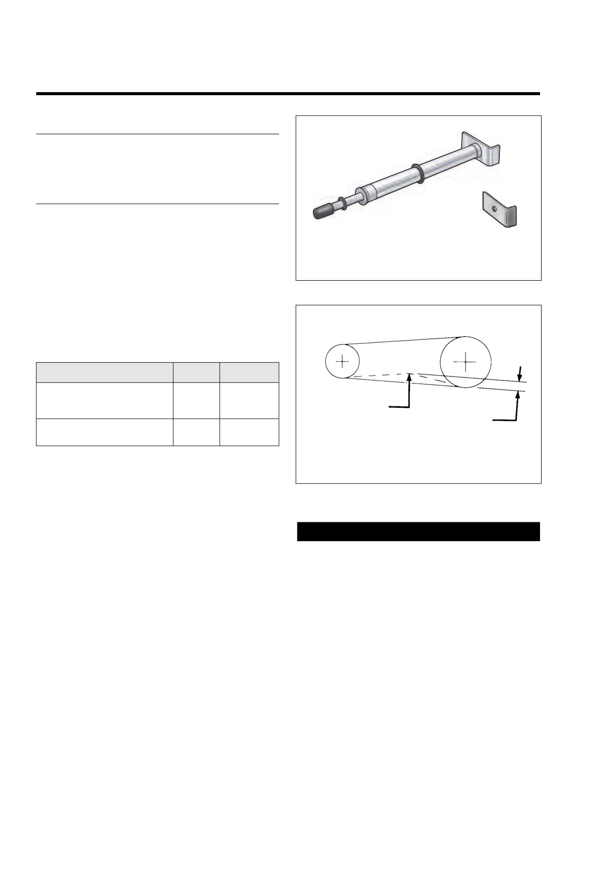
Obtain BELT TENSION GAUGE (HD-35381A), or install
1.
Belt Tension Gauge (Part No. HD-35381A)
adapter (HD-35381-3) on old style gauge. See Figure 1-
2.
Belt Tension Gauge Adapter (Part No. HD-35381-3)
13.
3.
Apply 10 lbs. (4.5 kg) of force at the midpoint of the bot-
Figure 1-13. Obtain Belt Tension Gauge
tom belt strand. See Figure 1-14. Check deflection at the
loosest spot in the belt with the transmission in neutral
and the motorcycle cold. Belt deflection should be as fol-
f1652x6x
lows:
2
1
Table 1-6. Belt Deflection
Orientation
Inches
Millimeters
On Jiffy Stand
Without Rider or Luggage
1/4 - 5/16
6.4
- 7.9
10 psi (69 kPa) in Rear Shocks
3
4
Motorcycle Upright
3/16 - 1/4
4.8
- 6.4
1.
Transmission Sprocket
With Rear Wheel in the Air
2.
Rear Wheel Sprocket
3.
10 lbs. (4.5 kg) of Force
If belt deflection is within specification, install left side
4.
Refer toTable 1-6.
saddlebag. If adjustment is necessary, move to step 4.
4.
Remove right side saddlebag. See Section 2.26 SAD-
Figure 1-14. Check and Adjust Belt Deflection
DLEBAG, REMOVAL.
5.
Standing on right side of motorcycle, remove E-clip from
groove at end of axle.
CAUTION
6.
Obtain torque wrench with 1/2 inch drive head and AXLE
Since any extension can act as a torque multiplier, the
NUT TORQUE ADAPTER (HD-47925). Proceed as fol-
torque wrench must be perpendicular to the torque
lows:
adapter when the cone nut is tightened. The 90 degree
NOTE
orientation between the tools cancels the multiplier
effect and prevents the cone nut from being over-tight-
The Axle Nut Torque Adapter simplifies the belt adjustment
ened. If the torque adapter is kept inline with the torque
procedure by allowing the cone nut to be properly tightened
wrench, the multiplier effect is in force and parts damage
without having to remove the right side muffler. The tool also
will occur.
can be used to loosen the cone nut, as well as rotate the
weld nut on the left side.
c. Loosen cone nut, and then snug to 15-20 ft-lbs (20-
27 Nm). See Figure 1-16.
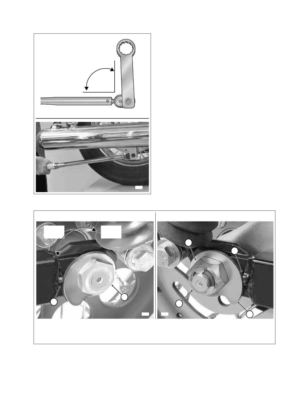
a. Install torque adapter perpendicular to torque
wrench as shown in Figure 1-15.
7.
If belt is too tight, move to step 8 to increase belt deflec-
tion. If belt is too loose, reduce belt deflection as follows:
b. Insert tool up between rear wheel and muffler to
capture cone nut. For best clearance with muffler,
a. Rotate weld nut on left side of axle in a clockwise
be sure torque adapter is on the outboard side.
direction.
1-20
2006 Touring: Maintenance
HOME
b. Check belt deflection. Apply 10 lbs. (4.5 kg) of force
1.
Torque Wrench
at the midpoint of the bottom belt strand. Belt
2.
Axle Nut Torque Adapter
2
deflection should be within the range specified in
(HD-47925)
Table 1-6.
c. If belt is still too loose, repeat steps 7(a) through
7(b). If belt is now too tight, move to step 8.
90°
8.
If belt is too tight, increase belt deflection as follows:
a. Using a hydraulic center stand, raise motorcycle so
that the rear wheel is off the ground.
1
b. Rotate weld nut on left side of axle in a counter-
clockwise direction.
c. Push wheel forward slightly so that adjuster cam
f2369x2x
just contacts weld nub on both sides of rear swing-
arm. See Figure 1-16.
d. Check belt deflection. Apply 10 lbs. (4.5 kg) of force
at the midpoint of the bottom belt strand. Belt
deflection should be within the range specified in
Table 1-6.
e. If belt is still too tight, repeat steps 8(b) through 8(d).
If belt is now too loose, move to step 7.
9.
Holding weld nut on left side of axle, tighten cone nut on
right side to 95-105 ft-lbs (128.8-142.4 Nm).
NOTE
9292
If the axle moves during tightening of the cone nut, then the
Figure 1-15.
Install Tool Perpendicular to Torque Wrench
belt deflection procedure must be restarted.
LEFT SIDE
RIGHT SIDE
Increase
Reduce
Belt
Belt
Deflection
Deflection
4
2
1
2
5
8398
8407
3
1.
Weld Nut
4.
Cone Nut
2.
Weld Nub
5.
E-Clip
3.
Adjuster Cam
Figure 1-16. Move Rear Wheel Forward Until Adjuster Cams Just Contact Weld Nubs
2006 Touring: Maintenance
1-21
HOME
10. Recheck belt deflection to verify that it is still within spec-
11. With the flat side out, install new E-clip in groove on right
ification.
side of axle.
If the belt deflection is not within specification, loosen
12. Install saddlebags. See Section
2.26 SADDLEBAG,
cone nut and then snug to 15-20 ft-lbs (20-27 Nm)
INSTALLATION.
before returning to step 7.
1-22
2006 Touring: Maintenance
HOME
THROTTLE CABLES
1.11
GENERAL
f1225x2x
See Section
1.2 MAINTENANCE SCHEDULE for the
required service interval.
PROCEDURE
LUBRICATION
CAUTION
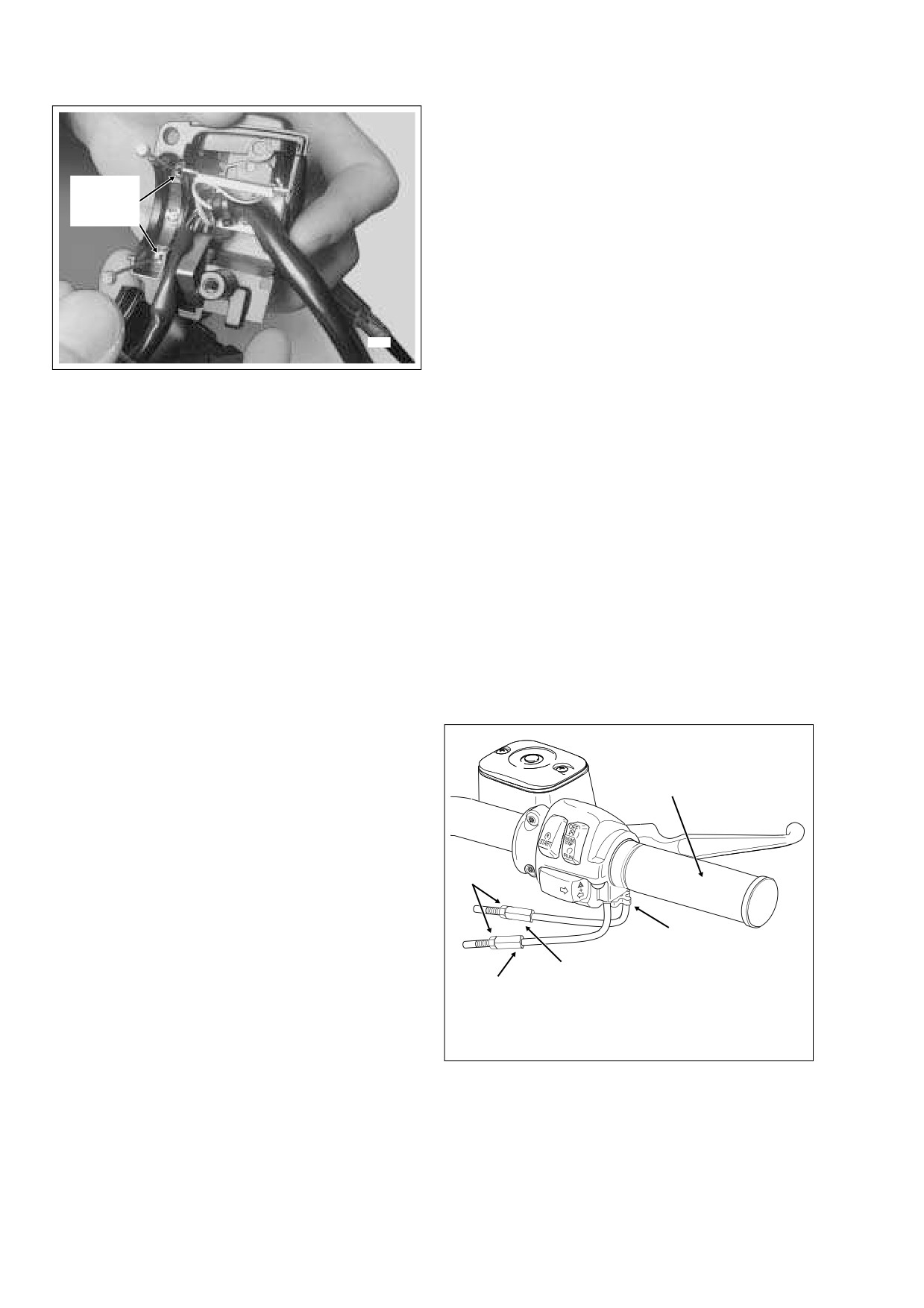
Do not remove the switch housing assembly without first
placing the 5/32 inch (4.0 mm) cardboard insert between
the brake lever and lever bracket. Removal without the
insert may result in damage to the rubber boot and
plunger of the Front Stoplight Switch.
NOTE
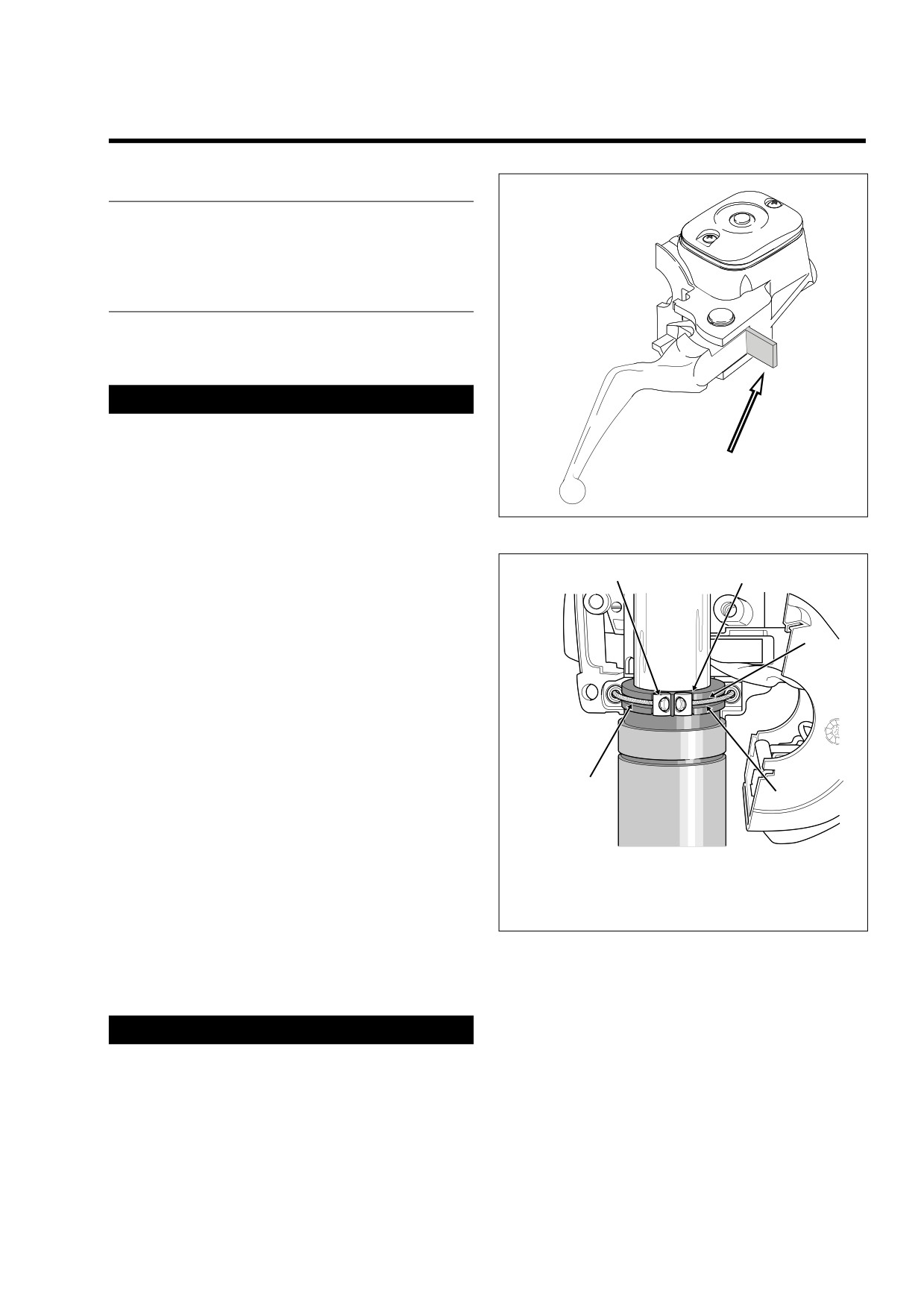
Figure 1-17. Install Cardboard Insert
Use the eyelet of an ordinary cable strap if the cardboard
insert is not available.
6
5
1.
Place the cardboard insert between the brake lever and
lever bracket. See Figure 1-17.
4
2.
Using a T25 TORX drive head, remove the upper and
lower switch housing screws.
3.
Using a T27 TORX drive head, loosen the upper screw
securing the handlebar clamp to the master cylinder
housing. Remove the lower clamp screw with flat
washer.
4.
Remove the brass ferrules from the notches on the
inboard side of the throttle grip. Remove the ferrules
2
from the cable end fittings. See Figure 1-18.
3
1
NOTE
f1474x2x
On non cruise equipped models, remove the friction shoe
from the end of the tension adjuster screw. The friction shoe
1.
Throttle Grip
4.
Groove
is a loose fit and may fall out or become dislodged if the lower
2.
Idle Cable
5.
Notch
switch housing is turned upside down or shaken.
3.
Throttle Cable
6.
Ferrule
5.
Remove the throttle grip from the end of the handlebar.
Figure 1-18. Remove Throttle/Idle Cables
6.
Move upper switch housing to the side in order to access
lower housing.
7.
Obtain tube of Lubit-8 Tufoil Chain and Cable Lube (HD
Part No. 94968-85TV- 1/4 fl. oz.). Insert pin of tube
1CAUTION
between throttle cable and cable housing inside lower
switch housing. Squeeze tube to squirt a quantity of
Lubit-8 Tufoil Chain and Cable Lube contains detergents.
lubricant into cable housing moving pin around cable
Avoid contact with eyes. Keep out of reach of children.
OD. See Figure 1-19.
2006 Touring: Maintenance
1-23
HOME
16. Using a T25 TORX drive head, tighten the lower and
upper switch housing screws to 35-45 in-lbs (4-5 Nm).
NOTE
Always tighten the lower switch housing screw first so that
Insert
any gap between the upper and lower housings is at the front
Lubricant
of the switch assembly.
Here
17. Remove the cardboard insert between the brake lever
and lever bracket.
18. Turn the Ignition/Light Key Switch to IGNITION and
apply brake lever to test operation of brake lamp.
ADJUSTMENT
7958
NOTE
For throttle and idle cable adjustment on cruise equipped
Figure 1-19. Lubricate Throttle/Idle Cables
models, see Section
8.31 CRUISE CONTROL (FLHRC,
FLHTCU, FLTR).
1.
Slide rubber boot off throttle cable adjuster mechanism.
8.
Repeat the procedure squirting a quantity of lubricant
See Figure 1-20. Holding cable adjuster with a 3/8 inch
between the idle cable and cable housing.
wrench, loosen jam nut turning in a clockwise direction.
Back jam nut away from cable adjuster until it stops. Turn
NOTE
cable adjuster clockwise until it contacts jam nut. Repeat
On non cruise equipped models, install the friction shoe with
procedure on idle cable adjuster.
the concave side up so that the pin hole is over the point of
2.
Point the front wheel straight ahead. Gently turn the
the adjuster screw. The friction shoe is a loose fit and may fall
throttle grip so that the throttle is wide open (fully coun-
out or become dislodged if the lower switch housing is turned
terclockwise) and then hold in position. Now turn the
upside down or shaken.
cable adjuster counterclockwise until the throttle cam
stop just touches the stop plate on the carburetor/induc-
9.
Apply a light coating of graphite to the handlebar.
tion module. See Figure 1-21. Release the throttle grip,
10.
Slide the throttle grip over the end of the right handlebar
turn cable adjuster counterclockwise an additional 1/2-1
until it bottoms against the closed end. Rotate the grip
full turn, and then tighten the jam nut against the cable
so that the ferrule notches are at the top. To prevent
adjuster. Cover cable adjuster mechanism with rubber
binding, pull the grip back about 1/8 inch (3.2 mm).
boot.
11.
Position the lower switch housing beneath the throttle
grip. Install the brass ferrules onto the cables so that the
end fittings seat in the ferrule recess. Seat the ferrules in
f1376b2x
their respective notches on the throttle grip. Verify that
the cables are captured in the grooves molded into the
4
grip. See Figure 1-18.
12.
Position the upper switch housing over the handlebar
and lower switch housing. Verify that the wire harness
conduit runs in the depression at the bottom of the han-
dlebar.
3
13.
Start the upper and lower switch housing screws, but do
not tighten.
5
14.
Position the brake lever/master cylinder assembly
inboard of the switch housing assembly engaging the
1
tab on the lower switch housing in the groove at the top
1.
Throttle Cable Adjuster
2
2.
Idle Cable Adjuster
of the brake lever bracket.
3.
Jam Nut
15.
Align the holes in the handlebar clamp with those in the
4.
Throttle Grip
master cylinder housing and start the lower screw (with
5.
Tension Adjuster Screw
flat washer). Position for rider comfort. Beginning with
the top screw, tighten the screws to 60-80 in-lbs (6.8-9.0
Figure 1-20. Throttle Cable Assembly - Throttle Side
Nm) torque using a T27 TORX drive head.
(FLHR/S)
1-24
2006 Touring: Maintenance
HOME
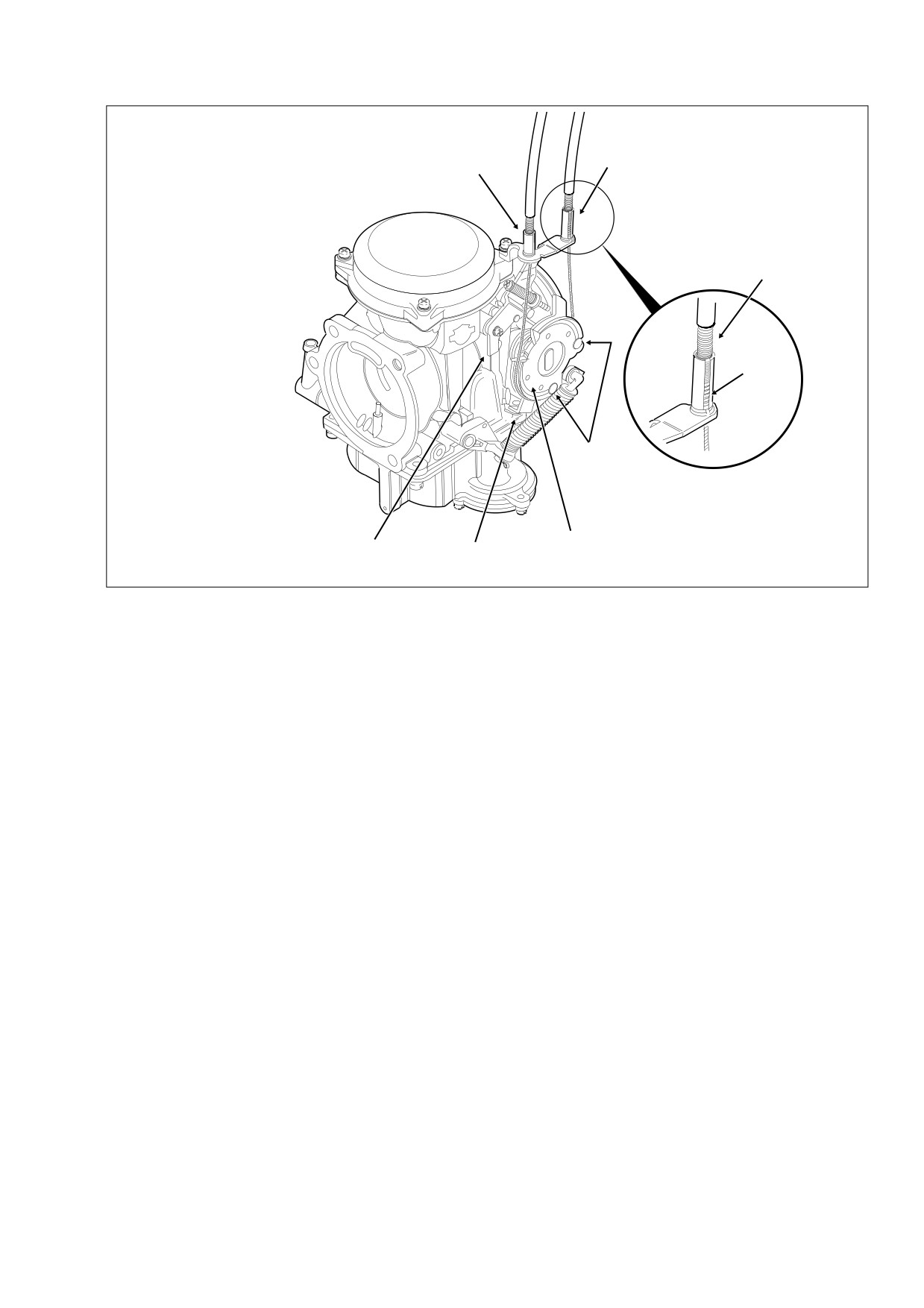
1.
Throttle Cable Guide
2.
Throttle Cam Stop
4
1
3.
Stop Plate
4.
Idle Cable Guide
5.
Cable Housing
6.
Spring
7.
Cable Barrel End
8.
Throttle Wheel
5
6
7
8
3
2
f1381a2x
Figure 1-21. Throttle Cable Assembly - Carburetor Side
3.
Turn the front wheel full right. Turn the idle cable adjuster
4.
Verify that the throttle control operates freely without
counterclockwise until the cable housing just touches
binding. With the tension adjuster screw backed off, the
the spring in the cable guide (as seen through slot).
throttle grip must freely return to the closed (idle) posi-
Work the throttle grip to verify that the throttle cable
tion. The throttle control also must open and close freely
returns to the idle position when released. If the cable
when the front wheel is turned to both the right and left
does not return to idle, turn the cable adjuster clockwise
fork stops. If the throttle grip does not return to the idle
slightly until the correct response is achieved. Tighten
position freely, check the adjuster screw tension
(if
jam nut against the cable adjuster and cover cable
present). If the adjuster screw is backed off, inspect the
adjuster mechanism with rubber boot.
cables for short bends.
2006 Touring: Maintenance
1-25
HOME
ENRICHENER CONTROL
1.12
GENERAL
f1438x4x
3
See Section
1.2 MAINTENANCE SCHEDULE for the
required service interval.
1
5
6
PROCEDURE
NOTE
The fuel enrichener knob should open, remain open and then
2
4
7
close without binding. The knurled plastic nut next to the
enrichener knob controls the ease at which the cable slides
within the conduit.
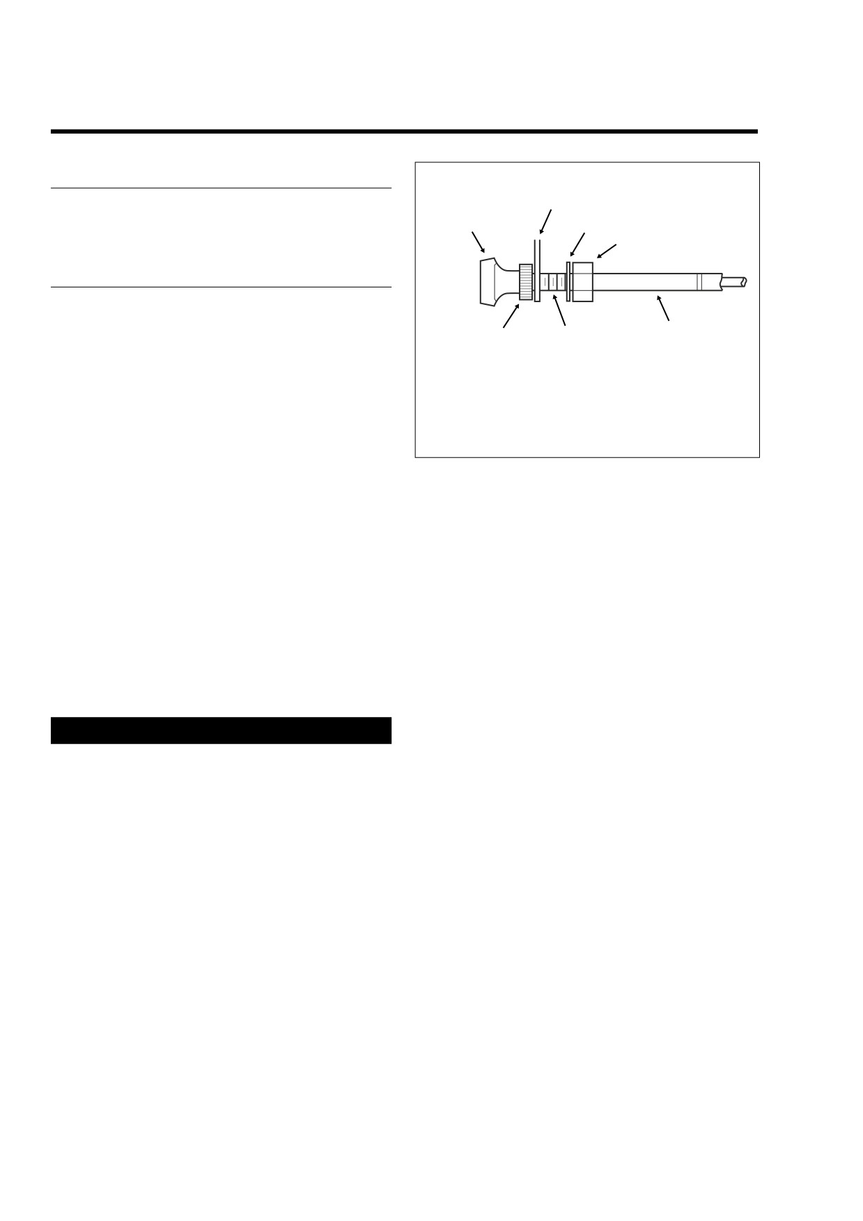
1.
Enrichener Knob
5.
Lockwasher
2.
Knurled Nut
6.
Hex Nut
If adjustment is needed, proceed as follows:
3.
Mounting Bracket
7.
Enrichener Cable
4.
Flat
1.
See Figure 1-22. Loosen hex nut at backside of mount-
ing bracket.
Figure 1-22. Enrichener Control
2.
Move cable assembly free of slot in mounting bracket.
3.
Hold cable assembly at flat with adjustable wrench.
Hand turn knurled nut counterclockwise to reduce sliding
resistance until knob slides inward unaided.
4.
Turn knurled nut clockwise to increase sliding resistance
until knob remains fully out without holding and then
closes with relative ease.
5.
Slide enrichener cable into slot of mounting bracket. Flat
on threads must face rear of motorcycle for script on
enrichener knob to be right side up. With external tooth
lockwasher and hex nut positioned on the inboard side
of the mounting bracket, tighten hex nut to 20-35 in-lbs
(2.3-4.0 Nm).
CAUTION
Do not lubricate the cable or inside of conduit. The cable
must have sliding resistance to work properly.
1-26
2006 Touring: Maintenance
HOME
FUEL SYSTEM
1.13
GENERAL
f1723x4x
See Section
1.2 MAINTENANCE SCHEDULE for the
required service interval.
PROCEDURE
LINES AND FITTINGS
8
Carefully inspect fuel system lines and fittings for leaks or
damage.
5
FUEL FILTER (CARBURETED)
7
4
1WARNING
9
6
When servicing the fuel system, do not smoke or allow
open flame or sparks in the vicinity. Gasoline is
extremely flammable and highly explosive, which could
result in death or serious injury. (00330a)
3
1.
Turn handle of fuel valve to OFF.
2
1WARNING
Gasoline can drain from the carburetor fuel line when
disconnected from fuel valve fitting. Gasoline is
10
1
extremely flammable and highly explosive, which could
result in death or serious injury. Wipe up spilled fuel
immediately and dispose of rags in a suitable manner.
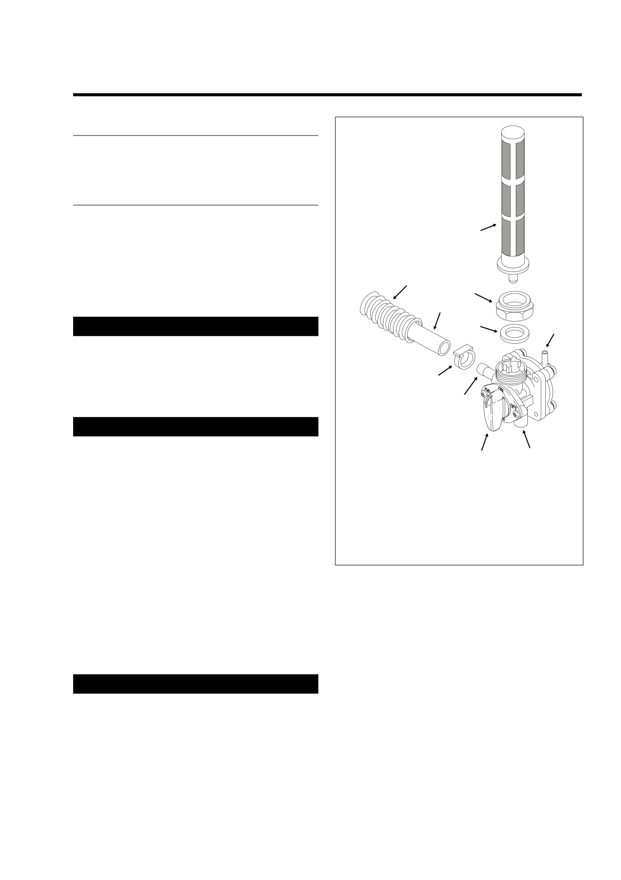
1.
Valve Handle
6.
Vacuum Fitting
(00256a)
2.
Fuel Outlet Fitting
7.
Jam Nut
3.
Hose Clamp
8.
Filter Strainer
2.
Using a side cutters, cut clamp and remove hose from
4.
Carburetor Fuel
9.
Gasket
fuel outlet fitting at front of fuel valve. See Figure 1-23.
Inlet Hose
10.
Atmospheric
Drain free end of hose into a suitable container.
5.
Convoluted Tubing
Pressure Port
3.
Remove elbow of intake manifold vacuum tube from fit-
ting on inboard side of fuel valve.
Figure 1-23. Vacuum Operated Fuel Valve
4.
Attach a length of fuel hose to the fuel outlet fitting. The
hose must be long enough to reach a suitable gasoline
7.
Gently apply a vacuum of 1-10 inches of Mercury (Hg) to
container.
vacuum fitting to get a good flow of gasoline through the
5.
Turn handle of fuel valve to RES(ERVE).
valve.
6.
Using the correct hose adapter, connect the Mity-Vac®
8.
When fuel tank is completely drained, remove Mity-Vac®
Hand Pump (HD-23738A) to vacuum fitting.
Hand Pump from the vacuum fitting.
9.
Holding fuel tank adapter, turn the hex jam nut in a
CAUTION
clockwise direction to remove fuel valve assembly.
To avoid damage to the diaphragm of the fuel valve, do
not apply a vacuum greater than 25 inches of Mercury
10. Remove fuel filter strainer from the valve head. Clean or
replace.
(Hg) to vacuum fitting.
2006 Touring: Maintenance
1-27
HOME
11. Remove hex jam nut from the fuel valve.
CAUTION
12. Remove gasket from the valve head. Discard the gasket.
Do not allow dirt or fluids to get into the vacuum tube
13. Install a new gasket on the valve head.
that connects the fuel valve to the intake manifold. Con-
taminants can block the vacuum signal which could
14. Install the fuel filter strainer fitting the internal tube into
cause the fuel valve to malfunction.
the larger hole in the valve head.
19. Connect elbow of intake manifold vacuum tube to fitting
on inboard side of fuel valve.
15. Clean threads and sealing surface of fuel tank adapter
and inspect for damage. Replace if necessary.
20. Slide new clamp onto free end of carburetor fuel inlet
hose. Install hose onto fuel outlet fitting at front of fuel
16. With hex side down, turn jam nut two full turns in a coun-
valve. Crimp clamp using HOSE CLAMP PLIERS (HD-
terclockwise direction to thread onto fuel tank adapter.
97087-65B).
17. Insert fuel filter strainer into fuel tank. Holding hex jam
21. Turn handle of fuel valve to OFF and fill the fuel tank.
nut to prevent rotation, turn fuel valve two full turns in a
Carefully inspect for leaks at fitting.
clockwise direction to thread onto hex jam nut.
22. Turn valve handle to ON and start engine. No priming or
special procedures are required to start fuel flow. Care-
1WARNING
fully inspect for leaks at fitting.
Do not thread fuel valve onto hex jam nut more than two
23. Stop engine and return valve to the OFF position.
turns or nut may “bottom” on valve, a condition which
may result in a gasoline leak. Any gasoline leak is a
potential fire hazard that could result in death or serious
FUEL FILTER CANISTER
injury.
(FUEL INJECTED)
18. Holding fuel valve to prevent rotation, turn hex jam nut in
See Section 9.4 FUEL TANK (FUEL INJECTED), FUEL FIL-
a counterclockwise direction until snug. Tighten hex jam
TER CANISTER, for replacement procedure.
nut to 15-20 ft-lbs (20.3-27.1 Nm).
1-28
2006 Touring: Maintenance
HOME
BRAKES
1.14
NOTE
GENERAL
Use only Harley-Davidson DOT 4 BRAKE FLUID, Part No.
See Section
1.2 MAINTENANCE SCHEDULE for the
99953-99A (12 ounce bottle), from a sealed container.
required service interval.
3.
Install cover (with gasket) on the master cylinder reser-
voir. Install two Phillips screws and tighten to 6-8 in-lbs
PROCEDURE
(0.7-0.9 Nm).
1WARNING
BRAKE FLUID
After repairing the brake system, test brakes at low
Inspect the brake fluid condition and level. Proceed as fol-
speed. If brakes are not operating properly, testing at
lows:
high speeds can cause loss of control, which could
result in death or serious injury. (00289a)
CAUTION
DOT 4 brake fluid will damage painted and molded-in
color surfaces it comes in contact with. Always use cau-
BRAKE PADS AND DISCS
tion and protect surfaces from spills whenever brake
work is performed. Failure to comply can result in cos-
Inspect the brake pads and discs as follows:
metic damage. (00239a)
Brake Pads
IMPORTANT NOTE
If brake pad friction material is worn to 0.04 inch (1.02 mm) or
Immediately wipe up any brake fluid spillage with a
less, replace the entire set of pads.
clean, dry, soft cloth. Follow up by thoroughly wiping
affected area with a clean, damp, soft cloth (small spills)
or washing with a large quantity of soapy water (large
1WARNING
spills).
Always replace brake pads in complete sets for correct
and safe brake operation. Improper brake operation
CAUTION
could result in death or serious injury. (00111a)
To prevent dirt and other contaminants from entering the
Brake Discs
master cylinder reservoir, thoroughly clean the cover
before removal.
The minimum brake disc thickness is stamped on the side of
the disc.
1.
Remove two Phillips screws from cover of master cylin-
der reservoir. Remove cover (with gasket).
When checking the brake pads and discs, inspect the brake
lines and hoses for damage or leaks.
1WARNING
Use only fresh, uncontaminated DOT 4 brake fluid. Fluid
containers that have been opened may have been con-
taminated by dirt or moisture. Use of contaminated
brake fluid may adversely affect braking ability and lead
to brake failure which could result in death or serious
injury.
IMPORTANT NOTE
The shelf life of a bottle of unopened DOT 4 brake fluid is
one year. The shelf life of an uncontaminated bottle that
has been opened and then resealed is one week.
2.
Stand the motorcycle upright so that the master cylinder
reservoir is in a level position. Fluid level should be 1/4
inch (6.4 mm) from the top. Add fluid as necessary.
2006 Touring: Maintenance
1-29
HOME
SPARK PLUGS
1.15
5.
Before installing spark plugs, check condition of threads
GENERAL
in cylinder head and on plug. If necessary soften depos-
its with penetrating oil and clean out with a thread
See Section
1.2 MAINTENANCE SCHEDULE for the
chaser.
required service interval.
6.
Apply a very light coating of ANTISEIZE LUBRICANT to
spark plug threads.
PROCEDURE
7.
Install spark plug finger tight and then torque to 12-18 ft-
lbs (16-24 Nm).
NOTE
1WARNING
If a torque wrench is not available, finger tighten spark plug
Never disconnect a spark plug cable with the engine run-
and then using a spark plug wrench, tighten plug an addi-
ning. Doing so will result in an electric shock from the
tional 1/4 turn.
ignition system that could result in death or serious
injury.
Table 1-7. Spark Plug Data
1.
Disconnect spark plug cables from spark plug terminals.
SIZE
12 mm
2.
Remove spark plug using a 5/8 inch spark plug socket.
3.
Examine plugs as soon as they have been removed. The
GAP
0.038-0.043 in. (0.97-1.09 mm)
deposits on the plug base are an indication of the plug
efficiency and are a guide to the general condition of
TYPE
HD-6R12 (No Substitute)
rings, valves, carburetor and ignition system.
a. A wet black and shiny deposit on plug base, elec-
NOTE
trodes and ceramic insulator tip indicate an oil
fouled plug. The condition may be caused by worn
The number 6R12 plug is supplied as original equipment and
rings and pistons, loose valves or seals, weak bat-
is the only plug that should be used. The resistor plug
tery or faulty ignition.
reduces radio interference created by the ignition system and
will not adversely affect performance or fuel economy.
b. A dry fluffy or sooty black deposit indicates a too
rich carburetor air-fuel mixture or long periods of
8.
Install spark plug cable from left side coil tower onto front
engine idling. Excessive use of the enrichener may
cylinder spark plug. Install spark plug cable from right
also cause this condition.
side coil tower onto rear cylinder spark plug.
c. An overheated plug can be identified by a light
brown, glassy deposit. This condition may be
accompanied by cracks in the insulator or by ero-
sion of the electrodes. This condition is caused by
too lean an air-fuel mixture, a hot running engine,
valves not seating or improper ignition timing. The
glassy deposit on the spark plug is a conductor
when hot and may cause high speed misfiring. A
plug with eroded electrodes, heavy deposits or a
cracked insulator should be replaced.
d. A plug with white, yellow or light tan to rusty brown
powdery deposit indicates balanced combustion.
The deposits may be cleaned off at regular intervals
if desired.
4.
Set the spark plug gap using a wire-type gauge. Bend
the outside electrode so only a slight drag on the gauge
is felt when passing it between electrodes. Never make
adjustments by bending the center electrode. Set gap on
all plugs at 0.038-0.043 in. (0.97-1.09 mm)
1-30
2006 Touring: Maintenance
HOME
ENGINE IDLE SPEED
1.16
GENERAL
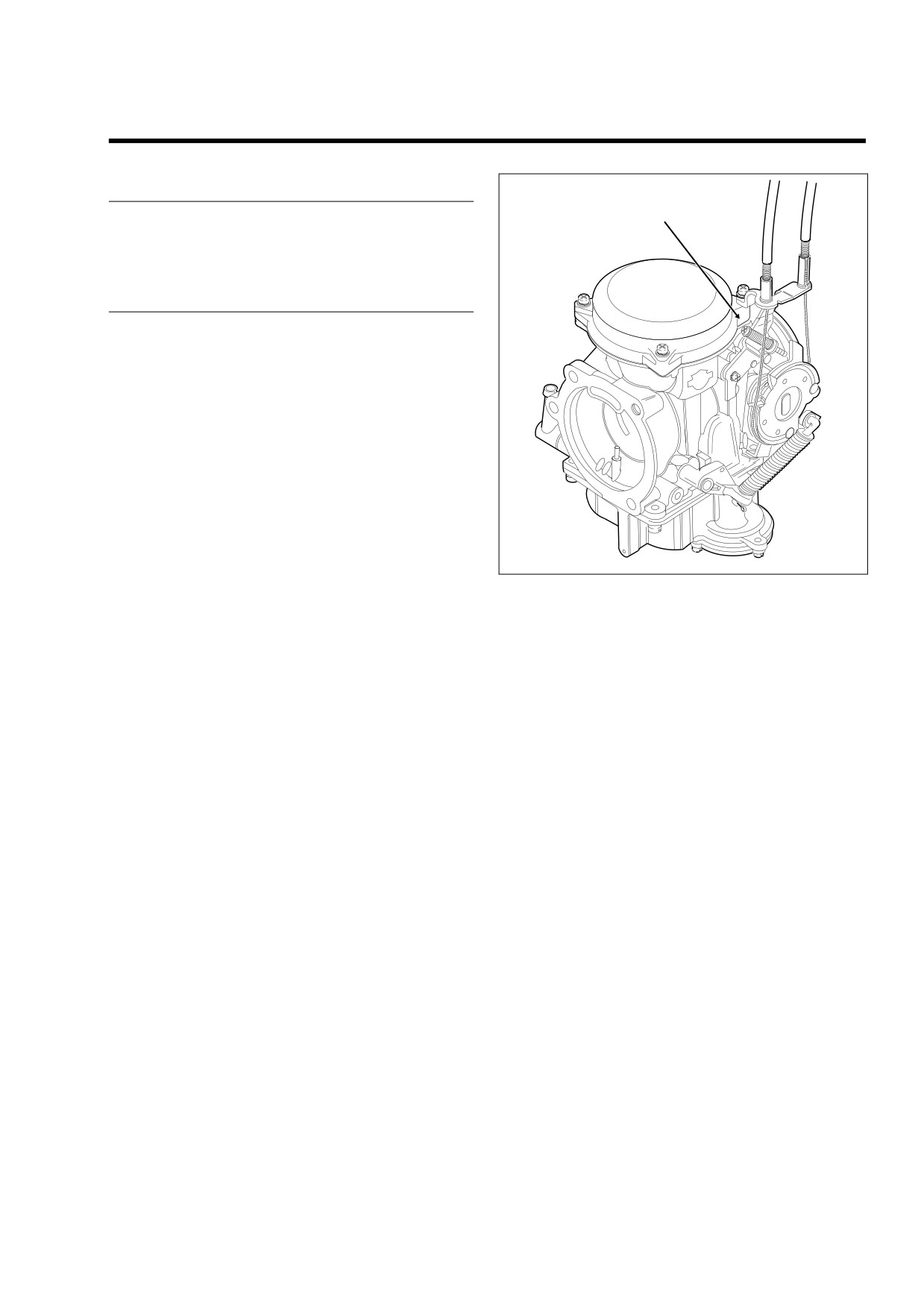
Throttle
Stop Screw
See Section
1.2 MAINTENANCE SCHEDULE for the
required service interval.
PROCEDURE
Inspect the engine idle speed as follows:
NOTES
● The C.V. carburetor has an enrichener circuit that will
cause the engine to idle at approximately 1500 rpm with
the engine at normal operating temperature and the
enrichener knob pulled fully out.
● The increase in idle speed is intended to alert the rider
that the engine is warmed up to normal operating tem-
perature and the enrichener knob should be pushed all
the way in.
f1381d2x
● Continuing to use the enrichener when the engine is at
full operating temperature WILL CAUSE FOULED
PLUGS.
Figure 1-24. Idle Speed Adjustment
● TECHNICIAN - Be sure the engine is warmed up to nor-
mal operating temperature and the enrichener knob is
pushed all the way in BEFORE adjusting engine idle
NOTE
speed. Be aware that because there are variations in
To measure engine rpm on models without tachometers, use
individual components, it is possible for a properly
a test tachometer connected to the negative ignition coil ter-
warmed up engine to idle at
2000 rpm with the
minal.
enrichener knob pulled PARTIALLY OUT.
1.
See Figure 1-24. With the engine at normal operating
temperature and the enrichener all the way in
(enrichener valve closed) adjust the throttle stop screw
so the engine idles at 950-1050 rpm.
2006 Touring: Maintenance
1-31
HOME
FRONT FORK OIL
1.17
GENERAL
See Section
1.2 MAINTENANCE SCHEDULE for the
required service interval.
PROCEDURE
See Section 2.15 FRONT FORKS for detailed instructions.
1-32
2006 Touring: Maintenance
HOME
STEERING HEAD BEARINGS
1.18
GENERAL
f2108x2x
See Section
1.2 MAINTENANCE SCHEDULE for the
required service interval.
PROCEDURE
GREASING
1.
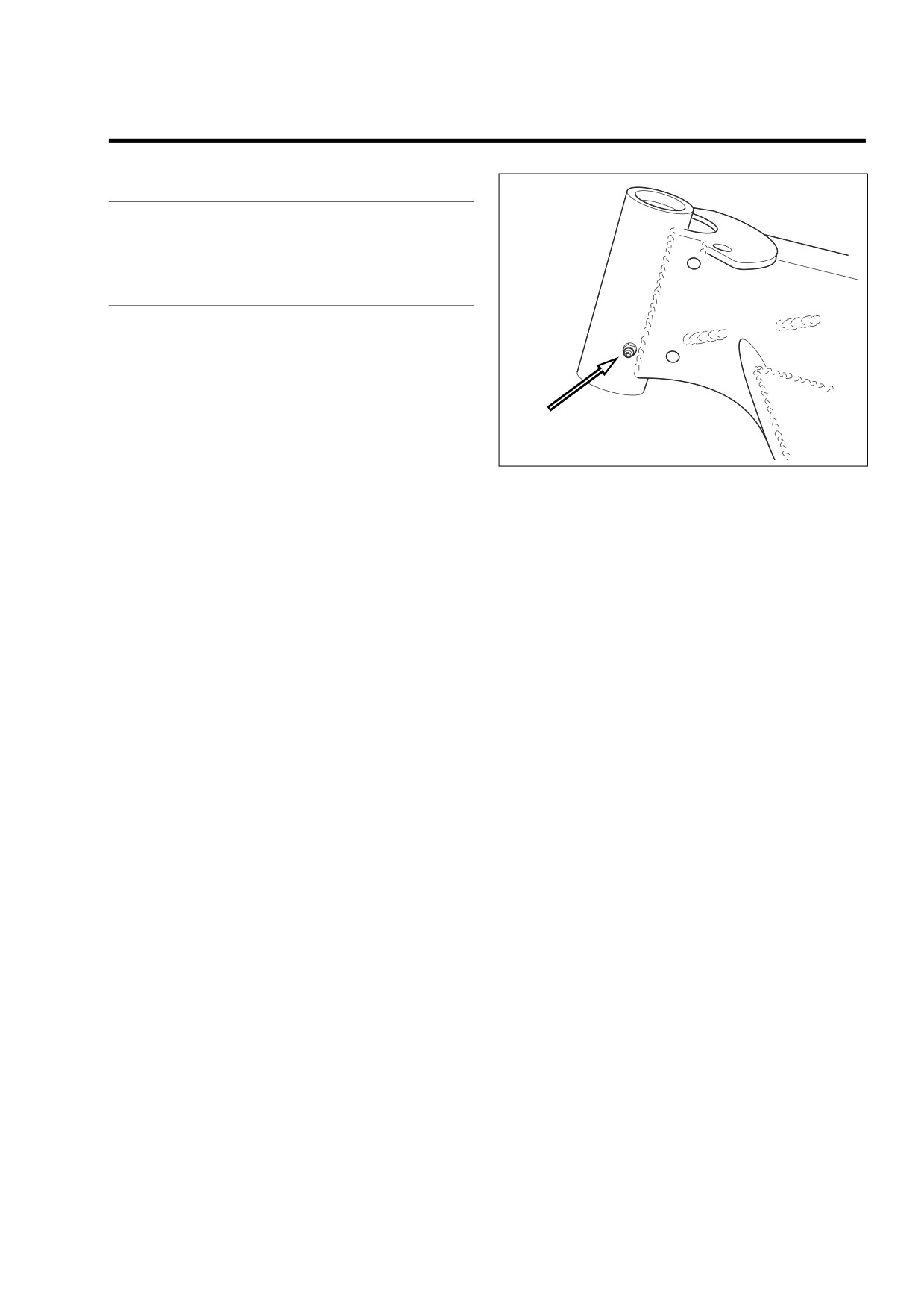
Turn handlebar full right to access the grease fitting at
the left side of the steering head. See Figure 1-25.
2.
Using SPECIAL PURPOSE GREASE (Part No. 99857-97),
connect grease gun to fitting and inject grease until it
exudes from top and bottom of steering head.
Figure 1-25. Steering Head Bearing Grease Fitting
CHECKING
Check the swing-by and adjust as necessary. See Section
2.17 STEERING HEAD BEARINGS for more information.
INSPECTING/REPLACING
Disassemble the steering head and inspect the bearings for
brinelling, scoring, or other damage. Replace and/or repack
the bearings as required. See Section
2.17 STEERING
HEAD BEARINGS for more information.
2006 Touring: Maintenance
1-33
HOME
CRITICAL FASTENERS
1.19
●
Tighten four engine to transmission bolts to 30-35 ft-lbs
GENERAL
(41-48 Nm).
See Section
1.2 MAINTENANCE SCHEDULE for the
NOTE
required service interval.
Install fuel tank. For carbureted models, see Section 4.7
FUEL TANK (CARBURETED), INSTALLATION (AFTER
PROCEDURE
PARTIAL REMOVAL), INSTALLATION (AFTER PARTIAL
REMOVAL), or FLHR/S. For fuel injected models, see Sec-
tion
9.4 FUEL TANK (FUEL INJECTED), INSTALLATION
ENGINE MOUNTS
(AFTER PARTIAL REMOVAL), FLHXI, FLHT/C/U/I, FLTRI, or
FLHR/C/S/I.
Inspect the condition and tightness of the stabilizer links and
engine mounts. Replace fastener if damaged. Proceed as fol-
lows:
OTHER FASTENERS
NOTE
Inspect the condition and tightness of other critical fasteners.
Raise fuel tank to access top engine stabilizer bolts and jam
Replace fastener if damaged. Proceed as follows:
nuts. For carbureted models, see Section 4.7 FUEL TANK
(CARBURETED), PARTIAL REMOVAL, FLHX, FLHT, or
FLHR/S. For fuel injected models, see Section 9.4 FUEL
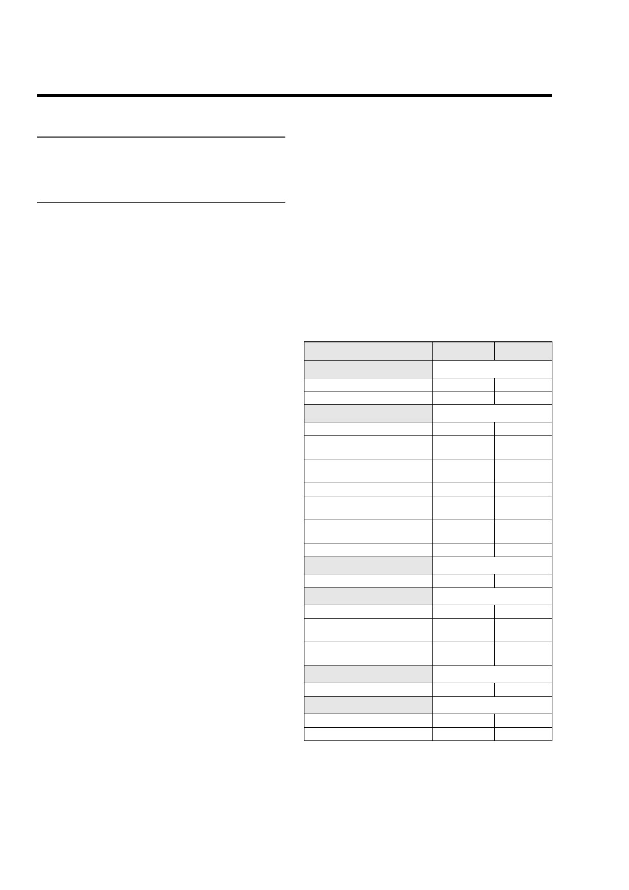
Table 1-8. Critical Fastener Torque
TANK (FUEL INJECTED), PARTIAL REMOVAL, FLHXI,
FLHT/C/U/I, FLTRI, or FLHR/C/S/I.
Fastener
ft/in-lbs
Nm
Axle
Top
Front axle nut
50-55 ft-lbs
68-75 Nm
● On left side of motorcycle, tighten top engine mounting
Rear axle cone nut
95-105 ft-lbs
129-142 Nm
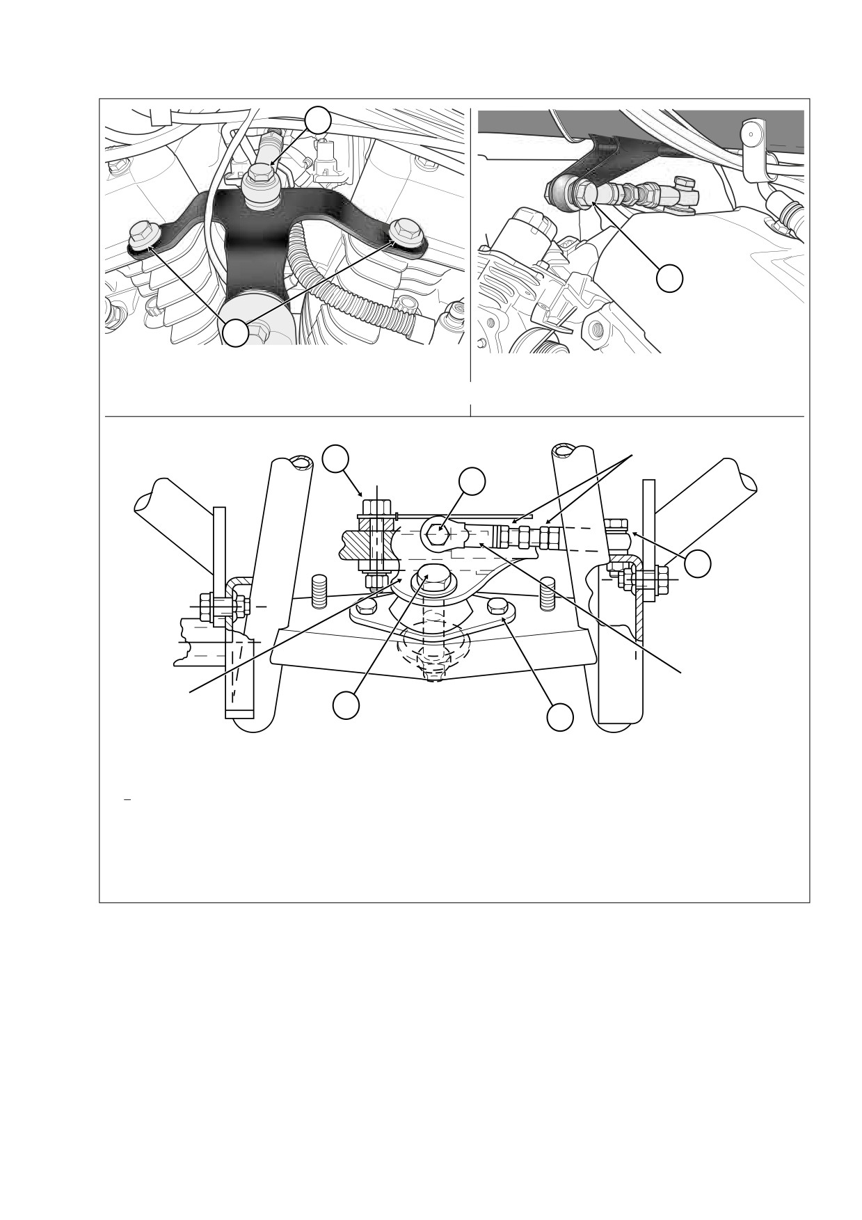
bracket bolts to front and rear cylinder heads to 35-40 ft-
Brakes
lbs (48-54 Nm). See A of Figure 1-26.
Banjo Bolts
17-22 ft-lbs
23-30 Nm
● Top stabilizer link - tighten eyelet bolt to top engine
Front Brake Disc Mounting
16-24 ft-lbs
22-33 Nm
mounting bracket to 18-22 ft-lbs (24-30 Nm). See B of
Screws
Figure 1-26.
Front Brake Caliper Mounting
28-38 ft-lbs
38-52 Nm
● Moving to right side of motorcycle, tighten eyelet bolt to
Bolts
frame weldment to 18-22 ft-lbs (24-30 Nm). See C of Fig-
Brake Caliper Pad Pins
180-200 in-lbs
20-23 Nm
ure 1-26.
Rear Brake Disc Mounting
30-45 ft-lbs
41-61 Nm
Screws
● Verify tightness of jam nuts on top stabilizer link.
Rear Master Cylinder Mounting
30-40 ft-lbs
41-54 Nm
Nut
Bottom
Reservoir Cover Screws
6-8 in-lbs
0.7-0.9 Nm
● Front stabilizer link - on left side of motorcycle, tighten
Front Forks
eyelet bolt to frame weldment to 18-22 ft-lbs (24-30 Nm).
See D of Figure 1-26.
Axle Holder Nuts
132-180 in-lbs
14.9-20.3 Nm
● Moving to right side of motorcycle, tighten eyelet bolt to
Hand Controls
block on front engine mounting bracket to 18-22 ft-lbs
Clutch Lever/Handlebar Clamp
60-80 in-lbs
6.8-9.0 Nm
(24-30 Nm). See E of Figure 1-26.
Master Cylinder/Handlebar
60-80 in-lbs
6.8-9.0 Nm
● Verify tightness of jam nuts on front stabilizer link.
Clamp Screws
● Tighten center front engine mounting bracket to rubber
Upper/Lower Switch Housing
35-45 in-lbs
4-5 Nm
Screws
mount bolt to 15-20 ft-lbs (20-27 Nm). See F of Figure 1-
26.
Handlebars
● Tighten the two front engine mount to frame crossmem-
Lower Clamp (Riser) Bolts
30-40 ft-lbs
40.7-54.2 Nm
ber bolts to 15-20 ft-lbs (20-27 Nm). See G of Figure 1-
Pivot Shaft
26.
Locknuts
40-45 ft-lbs
54-61 Nm
● Tighten two engine to front engine mounting bracket
Swingarm Bracket Bolts
34-42 ft-lbs
46-57 Nm
bolts to 33-38 ft-lbs (45-52 Nm). See H of Figure 1-26.
1-34
2006 Touring: Maintenance
HOME
B
C
A
LEFT SIDE
RIGHT SIDE
Top Stabilizer Link and Engine Mounting Bracket
f2181x2x
f2111x2x
Jam Nut
H
E
D
Front
Stabilizer Link
Front Engine
F
Mounting Bracket
G
f1303x2x
Front Stabilizer Link and Engine Mounting Bracket
Top
Bottom
A Top Engine Mounting Bracket to Cylinder Heads
D Eyelet to Frame Weldment
B Eyelet to Top Engine Mounting Bracket
E Eyelet to Front Engine Mounting Bracket
C Eyelet to Frame Weldment
F Front Engine Mounting Bracket to Rubber Mount
G Front Engine Mount to Frame Crossmember
H Engine to Front Engine Mounting Bracket
Figure 1-26. Engine Mounting Bracket Bolts
2006 Touring: Maintenance
1-35
HOME
BATTERY
1.20
3.
Inspect battery for discoloration, raised top, or warped
GENERAL
case, which may indicate that battery has been over-
heated or overcharged. Inspect battery case for cracks
See Section
1.2 MAINTENANCE SCHEDULE for the
or leaks. Replace battery if any of these conditions are
required service interval.
found.
NOTE
For testing or charging information, see Section 8.10 BAT-
PROCEDURE
TERY.
4.
Coat battery terminals with ELECTRICAL CONTACT
1.
Verify that battery top is clean and dry. Dirt on top of bat-
LUBRICANT, Part No. 99861-02 (1 oz tube).
tery may cause it to self-discharge at a faster than nor-
mal rate.
2.
Inspect battery clamp, screws and cables for breakage,
loose connections and corrosion. Clean or replace as
necessary.
1-36
2006 Touring: Maintenance
HOME
TROUBLESHOOTING
1.21
10. Ignition timing incorrect due to faulty ignition coil, ignition
GENERAL
module or sensors (MAP, CKP and/or TSM/TSSM).
The following check list of possible operating troubles and
11. Engine lubricant too heavy (winter operation).
their probable causes will be helpful in keeping your motorcy-
NOTE
cle in good operating condition. More than one of these con-
Always disengage clutch for cold weather starts.
ditions may be causing the trouble and all should be carefully
checked.
12. Sticking or damaged valve or push rod wrong length.
13. Primary cam sprocket spline sheared or missing spacer.
1WARNING
The troubleshooting section of this manual is a guide to
Starts Hard
diagnose problems. Read the appropriate sections of
1.
Spark plugs in bad condition, have improper gap or are
this manual before performing any work. Improper repair
partially fouled.
and/or maintenance could result in death or serious
injury.
2.
Spark plug cables in bad condition.
3.
Battery nearly discharged.
ENGINE
4.
Loose wire connection at one of the battery terminals,
ignition coil or plug between ignition sensor and module.
5.
Carburetor controls not adjusted correctly.
Starter Motor Does Not Operate or Does
6.
Water or dirt in fuel system and carburetor.
Not Turn Engine Over
7.
Intake air leak.
1.
Ignition/Light Key Switch not in IGNITION position.
8.
Fuel tank vent hose and vapor valve plugged, or carbu-
2.
Engine Stop switch in the OFF position.
retor fuel line closed off and restricting fuel flow.
3.
Discharged battery, loose or corroded connections
9.
Enrichener valve inoperative.
(solenoid chatters).
10. Engine lubricant too heavy (winter operation).
4.
TSM/TSSM BAS tripped and Ignition/Light Key Switch
NOTE
not cycled to OFF and then back to IGNITION.
Always disengage clutch for cold weather starts.
5.
Starter control circuit, relay or solenoid faulty.
11. Ignition not functioning properly (possible sensor failure).
6.
Electric starter shaft pinion gear not engaging or over-
running clutch slipping.
12. Faulty ignition coil.
13. Valves sticking.
Engine Turns Over But Does Not Start
Starts But Runs Irregularly or Misses
1.
Fuel tank empty.
2.
Fuel supply valve turned to OFF.
1.
Spark plugs in bad condition or partially fouled.
3.
Fouled spark plugs.
2.
Spark plug cables in bad condition and leaking.
4.
Engine flooded with gasoline as a result of over use of
3.
Spark plug gap too close or too wide.
enrichener.
4.
Faulty ignition coil, module and/or sensor.
5.
Fuel valve or filter clogged.
5.
Battery nearly discharged.
6.
Vacuum hose to automatic fuel supply valve discon-
6.
Damaged wire or loose connection at battery terminals,
nected, leaking or pinched.
ignition coil, or plug between ignition sensor and module.
7.
Discharged battery, loose or broken battery terminal
7.
Intermittent short circuit due to damaged wire insulation.
connections.
8.
Water or dirt in fuel system, carburetor or filter.
8.
Loose wire connection at coil, battery or plug between
9.
Fuel tank vent system plugged or carburetor vent line
ignition sensor and module.
closed off.
9.
Spark plug cables in bad condition and shorting, cable
10. Carburetor controls misadjusted.
connections loose, or cables connected to wrong cylin-
ders.
11. Damaged carburetor.
2006 Touring: Maintenance
1-37
HOME
12. Loose or dirty ignition module connector at crankcase.
4.
Engine to transmission mounting bolts loose.
13. Faulty MAP and/or CKP Sensor.
5.
Upper engine mounting bracket loose.
14. Incorrect valve timing.
6.
Ignition timing incorrect/poorly tuned engine.
15. Weak or broken valve springs.
7.
Internal engine problem.
16. Damaged intake or exhaust valve.
8.
Broken frame.
9.
Stabilizer links worn or loose.
A Spark Plug Fouls Repeatedly
10. Rubber mounts loose or worn.
11. Rear fork pivot shaft nuts loose.
1.
Fuel mixture too rich or enrichener left out too long.
12. Front engine mounting bolts loose.
2.
Incorrect spark plug for the kind of service.
3.
Piston rings badly worn or broken.
Check Engine Lamp Illuminates During
4.
Valve guides or seals badly worn.
Operation
1.
Fault detected. Check for trouble codes.
Pre-Ignition or Detonation (Knocks or
Pings)
1.
Fuel octane rating too low.
LUBRICATION SYSTEM
2.
Faulty spark plugs.
3.
Incorrect spark plug for the kind of service.
Oil Does Not Return To Oil Pan
4.
Excessive carbon deposit on piston head or in combus-
tion chamber.
1.
Oil pan empty.
5.
Ignition timing advanced due to faulty sensor inputs
2.
Oil pump not functioning.
(MAP, CKP).
3.
Restricted oil lines or fittings.
4.
Restricted oil filter.
Overheating
5.
Oil pump misaligned or in poor condition.
1.
Insufficient oil supply or oil not circulating.
6.
O-ring damaged or missing from oil pump/crankcase
2.
Insufficient air flow over engine.
junction (also results in poor engine performance).
3.
Heavy carbon deposit.
4.
Ignition timing retarded due to faulty MAP and/or CKP
Engine Uses Too Much Oil Or Smokes
Sensor.
Excessively
5.
Leaking valve.
1.
Oil pan overfilled.
2.
Restricted oil return line to pan.
Valve Train Noise
3.
Restricted breather operation.
1.
Low oil pressure caused by oil feed pump not functioning
4.
Restricted oil filter.
properly or oil passages obstructed.
5.
Oil pump misaligned or in poor condition.
2.
Faulty hydraulic lifters.
6.
Piston rings badly worn or broken.
3.
Bent push rod.
7.
Valve guides or seals worn.
4.
Incorrect push rod length.
8.
O-ring damaged or missing from oil pump/crankcase
5.
Rocker arm binding on shaft.
junction (also results in poor engine performance).
6.
Valve sticking in guide.
7.
Chain tensioner spring or shoe worn.
Engine Leaks Oil From Case, Push Rods,
Hoses, Etc.
Excessive Vibration
1.
Loose parts.
1.
Wheels and/or tires worn or damaged.
2.
Imperfect seal at gaskets, push rod cover, washers, etc.
3.
Restricted oil return line to pan.
2.
Engine/transmission/motorcycle not aligned properly.
4.
Restricted breather hose to air cleaner.
3.
Primary chain badly worn or links tight as a result of
insufficient lubrication or misalignment.
5.
Restricted oil filter.
1-38
2006 Touring: Maintenance