Harley Davidson 2008 Touring Models. Service Manual - page 19
 

  Главная      Harley Davidson     Harley Davidson 2008 Touring Models. Service Manual


Search            copyright infringement  


Content      ..     17      18      19      20     ..


Harley Davidson 2008 Touring Models. Service Manual - page 19


3.1

SPECIFICATIONS

SPECIFICATIONS

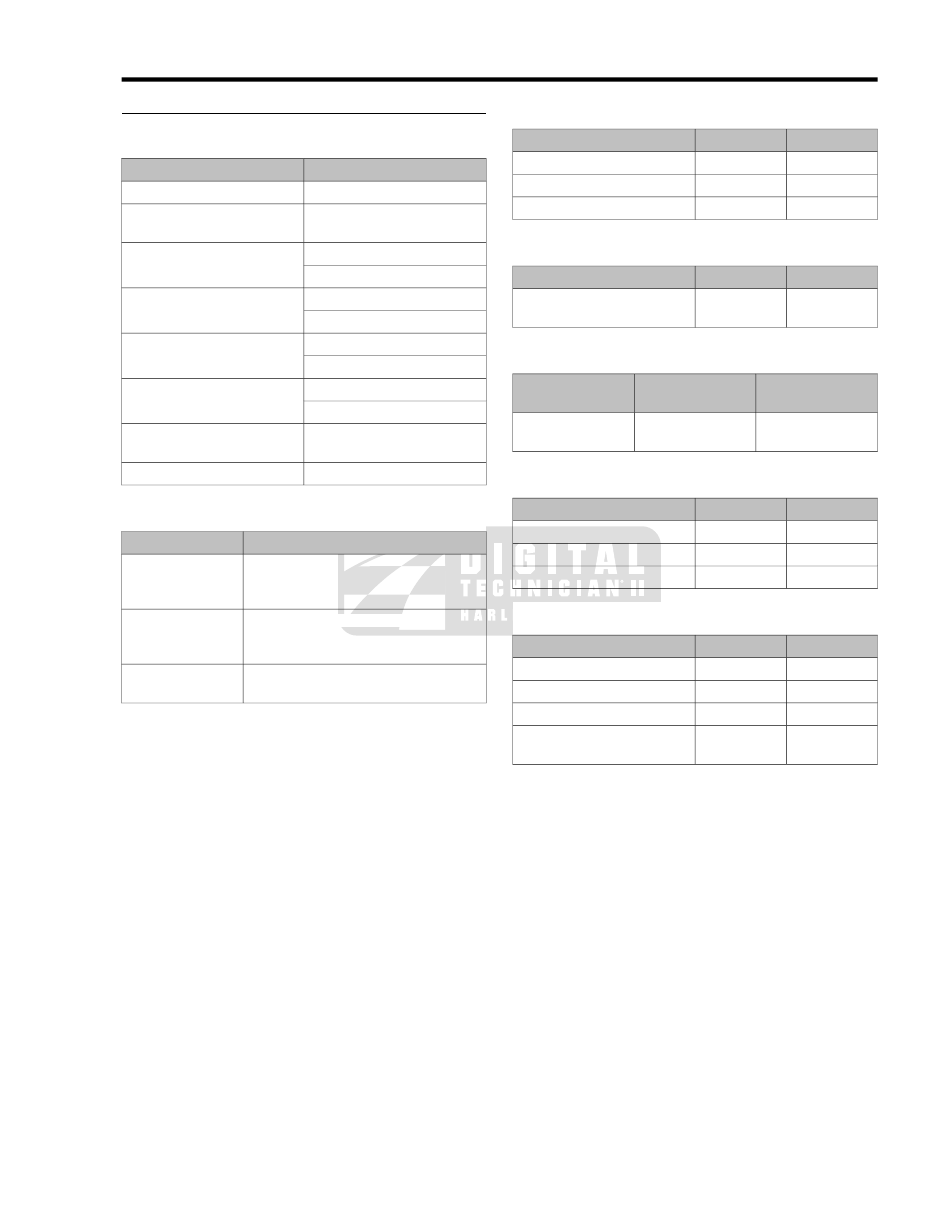
Table 3-1. General Specifications

DATA

GENERAL

2

Number of cylinders

4-cycle, 45 degree, air-cooled

V-twin

Type

91 ft-lbs @ 3000 RPM

Torque
(with shorty, dual exhaust)

123 Nm @ 3000 RPM

3.75 in.

Bore

95.25 mm

4.375 in.

Stroke

111.13 mm

96 cubic in.

Piston displacement (approx.)

1584 cc

5500 RPM

Maximum sustained engine
speed

1000 RPM +/- 50

Idle speed

Table 3-2. Oil Pump Specifications

DATA

OIL PUMP

Twin geroter, dual scavenge, crank

mounted and driven, internal oil pump,

dry sump

Type

30-38 PSI (207-262 kN/m

2

) at 2000

RPM and normal operating temperature

of  230° F (110° C)

Pressure

5 micron media, filtered between pump

and engine

Filtration

Table 3-3. Rocker Arms Specifications

MM

IN.

ROCKER ARMS

0.013-0.051

0.0005-0.0020

Shaft fit in bushing (loose)

0.08-0.33

0.003-0.013

End clearance

0.051-0.102

0.002-0.004

Bushing fit in rocker arm (tight)

Table 3-4. Rocker Arm Shaft Specifications

MM

IN.

ROCKER ARM SHAFTS

0.018-0.056

0.0007-0.0022

Shaft fit in rocker arm support
plate (loose)

Table 3-5. Hydraulic Lifter Specifications

MM

IN.

HYDRAULIC
LIFTERS

0.02-0.05

0.0008-0.0020

Fit in crankcase
(loose)

Table 3-6. Cylinder Head Specifications

MM

IN.

CYLINDER HEAD

0.051-0.084

0.0022-0.0033

Valve guide in head (tight)

0.076-0.114

0.003-0.0045

Valve seat in head (tight)

0-0.152

0-0.006

Head gasket surface (flatness)

Table 3-7. Valve Specifications

MM

IN.

VALVES

0.0254-0.0762

0.001-0.003

Exhaust: fit in guide

0.0254-0.0762

0.001-0.003

Intake: fit in guide

1.02-1.58

0.040-0.062

Seat Width

51.10-51.61

2.012-2.032

Stem protrusion from cylinder
head boss

2008 Touring Service:  Engine  3-1

Table 3-8. Valve Springs Specifications

MM

IN.

VALVE
SPRINGS

61.2 kg @ 47.0 mm

135 lbs @ 1.850 in.

Closed

141.5 kg @ 33.0 mm

312 lbs @ 1.300 in.

Open

59.1 mm

2.325 in.

Free length

Table 3-9. Piston

REPLACE IF WEAR

EXCEEDS

PISTON

MM

IN.

0.036-0.064

0.0014-0.0025

Fit in cylinder (loose)

0.00-0.013

0.0002-0.0005

Piston pin fit (loose)

0.254-0.508

0.010-0.020

Top compression

Ring end
gap

0.356-0.610

0.014-0.024

2nd compression

0.254-1.27

0.010-0.050

Oil control ring

0.030-0.094

0.0012-0.0037

Top compression

Ring side
clear-
ance

0.030-0.094

0.0012-0.0037

2nd compression

0.079-0.231

0.0031-0.0091

Oil control rails

Table 3-10. Connecting Rod Specifications

MM

IN.

CONNECTING ROD

0.018-0.030

0.0007-0.0012

Piston pin fit (loose)

0.13-0.38

0.005-0.015

Side play between fly-
wheels

0.0102-0.0432

0.0004-0.0017

Connecting rod to
crankpin (loose)

Table 3-11. Flywheel Specifications

MM

IN.

FLYWHEELS

0.0-0.254

0.000-0.010

Runout (shaft measured
in case)

0.0-0.102

0.000-0.004

Runout (measured in
truing stand)

0.076-0.254

0.003-0.010

End play

Table 3-12. Crankshaft/Sprocket Shaft Bearing

Specifications

MM

IN.

CRANK-
SHAFT/SPROCKET
SHAFT BEARINGS

0.005-0.038

0.0002-0.0015

Roller bearing fit (loose)

0.097-0.137

0.0038-0.0054

Bearing fit in crankcase
(tight)

0.010-0.036

0.0004-0.0014

Bearing inner race on
crankshaft (tight)

3-2  2008 Touring Service:  Engine

3.2

SERVICE WEAR LIMITS

GENERAL

Wear limits are given here as a guideline for measuring used
engine components. Replace components when they exceed
values listed here.

Table 3-13. Rocker Arm/Rocker Arm Shaft

REPLACE IF WEAR EXCEEDS

ROCKER ARM/ROCKER
ARM SHAFT

MM

IN.

0.089

0.0035

Shaft fit in bushing (loose)

0.635

0.025

End clearance

0.089

0.0035

Shaft fit in rocker arm
support (loose)

Table 3-14. Hydraulic Lifter

REPLACE IF WEAR EXCEEDS

HYDRAULIC LIFTER

MM

IN.

0.076

0.003

Fit in crankcase

0.038

0.0015

Roller fit

0.559

0.022

Roller end clearance

Table 3-15. Cam Support Plate

REPLACE IF

CAM SUPPORT PLATE

MM

IN.

More than 2.29

More than 0.090

Cam chain tensioner shoe

1/2 thickness of shoe

More than

21.704

More than

0.8545

Crankshaft bushing max-
imum ID

27.998

1.1023

Camshaft bore

Table 3-16. Cylinder Head

REPLACE IF

CYLINDER HEAD

MM

IN.

Less than

0.051

Less than

0.002

Valve guide in head (tight)

Less than

0.051

Less than

0.002

Valve seat in head (tight)

More than

0.152

More than

0.006

Head warpage

Table 3-17. Cylinder

REPLACE IF WEAR EXCEEDS

CYLINDER

MM

IN.

0.051

0.002

Taper

0.051

0.002

Out of round

0.152

0.006

Warpage of gasket sur-
faces: top

0.102

0.004

Warpage of gasket or O-
ring surfaces: base

Table 3-18. Cylinder Bore

REPLACE IF WEAR EXCEEDS

CYLINDER BORE

MM

IN.

95.301

3.752

Standard

95.428

3.757

0.005 in. oversize

95.555

3.762

0.010 in. oversize

Table 3-19. Piston

REPLACE IF WEAR

EXCEEDS

PISTON

MM

IN.

0.076

0.003

Fit in cylinder (loose)

0.020

0.0008

Piston pin fit (loose)

0.762

0.030

Top compression

Ring end
gap

0.864

0.034

2nd compression

1.27

0.050

Oil control rails

0.114

0.0045

Top compression

Ring side
clearance

0.114

0.0045

2nd compression

0.254

0.010

Oil control rails

Table 3-20. Connecting Rod

REPLACE IF WEAR

EXCEEDS

CONNECTING ROD

MM

IN.

0.051

0.002

Piston pin fit (loose)

0.508

0.020

Side play between flywheels

0.051

0.002

Fit on crankpin (loose)

Table 3-21. Breather Assembly

REPLACE IF WEAR

EXCEEDS

BREATHER ASSEMBLY

MM

IN.

0.13

0.005

Breather cover warpage

0.13

0.005

Breather baffle warpage

2008 Touring Service:  Engine  3-3

Table 3-22. Valve Stem to Guide

REPLACE IF WEAR EXCEEDS

VALVE STEM TO GUIDE

MM

IN.

0.0965

0.0038

Intake

0.0965

0.0038

Exhaust

Table 3-23. Flywheel

REPLACE IF WEAR EXCEEDS

FLYWHEEL

MM

IN.

0.305

0.012

Runout (shaft measured
in case)

0.127

0.005

Runout (measured in
truing stand)

0.254

0.010

End play

Table 3-24. Crankshaft Roller Bearing

REPLACE IF

CRANKSHAFT ROLLER
BEARING

MM

IN.

More than 0.038

More than

0.0015

Roller bearing fit (loose)

Less than 0.097

Less than

0.0038

Bearing fit in crankcase
(tight)

Less than 0.010

Less than

0.0004

Inner race on crankshaft
(tight)

3-4  2008 Touring Service:  Engine

3.3

ENGINE OIL FLOW

OIL FEED

NOTE

The oiling system is carefully designed for optimum efficiency.
All oil holes and passageways are specially sized. Exercise
caution to avoid enlarging oil holes during cleaning. Any
modification of the oiling system will adversely affect oil pres-
sure or cooling and lubrication efficiency.

Two illustrations accompany this explanation.

Cam support plate oil flow is shown in 

Figure 3-1

.

Top end oil flow is shown in 

Figure 3-2

.

Oil flows from the oil pan through an internal passageway at
the front of the transmission housing, and enters the lower
passageway (A1) cast into the rear right side of the crankcase.

Running through a passageway in the crankcase, oil exits a
hole in the crankcase flange (B2) and enters a hole on the
inboard side of the cam support plate. Passing through a
channel in the cam support plate (A3), the oil enters the feed
side of the oil pump. See 

3.4 OIL PUMP OPERATION

. The

feed gerotors of the pump direct the flow up a second channel
in the cam support plate (A4).

A drilling in this channel connects to a pressure relief valve
mounted in the bypass port of the cam support plate (A5).
When the oil pressure exceeds the setting of the relief valve
spring ( 35 psi (241.3 kPa) ), the orfice opens to bypass excess
oil back to the feed side of the pump (A3).

Oil not returned to the feed side exits a hole on the inboard
side of the cam support plate and passes through a hole in the
crankcase flange (B6). Flowing through a passageway in the
crankcase, where a reading is taken by the oil pressure sending
unit (B7), the oil exits the lower off-center hole in the oil filter
mount (D8).

After circulating through the oil filter, the flow of oil is directed
back into the crankcase through the center hole in the oil filter
mount (D9). Exiting a passageway in the crankcase through a
hole in the crankcase flange (B10), the flow of oil reenters the
cam support plate.

Filtered oil is then routed to the top and bottom ends of the
engine as described in 

3.3 ENGINE OIL FLOW, Top End

 and

3.3 ENGINE OIL FLOW, Bottom End

 which follow.

TOP END

Two illustrations accompany this explanation.

Cam support plate oil flow is shown in 

Figure 3-1

.

Top end oil flow is shown in 

Figure 3-2

.

Oil passes through a channel in the cam support plate exiting
the inboard side through two holes near the top (A11, A12).
Entering two holes in the crankcase flange (B13, B14), one
leading to the front cylinder and the other to the rear, the oil
travels through passageways in the crankcase to the hydraulic
lifter bores (D15).

Exiting a hole in each lifter bore (E16), the oil flows around the
lifter and enters a hole at the side of the lifter body. As the
chamber inside the lifter body is filled, the push rod socket rises
to achieve the no-lash fit of the valve train components. The

flow of oil then exits a hole centered in the lifter socket and
runs up the hollow push rods.

NOTE

Note that there is one additional hole drilled into the inside lifter
bores while the oblong hole circulates oil around the lifter body
as described, the round hole (E17) feeds oil to the piston jets
in the flywheel compartment.

Exiting holes at the top of the hollow push rods, oil enters a
hole at the bottom of the intake and exhaust rocker arms.
Lubricating the rocker arm bushings, oil flows down the rocker
arm shafts and exits a pin hole in the outboard side of each
rocker arm housing (F18) where it sprays the valve springs
and the top of the valve stem.

Oil runs down to the low side of the rocker housing and enters
the exhaust valve spring pocket where a drain hole (G19) leads
to a passageway in the cylinder head casting.

Oil exits the bottom of the cylinder head and passes through
a dowel pin (H20) on the "down side" of the cylinder flange.
The oil runs through a vertical passageway in the cylinder,
passes through a second dowel pin on the "down side" of the
cylinder deck (I21) and enters the left crankcase half.

Flowing through a horizontal passageway in the left crankcase
half (J22), oil runs through a third dowel pin (K23) to the right
crankcase half where it travels through another passageway
before emptying into the cam compartment (B23, B24).

Oil collecting in the cam compartment is picked up by one of
two scavenge lobes on the oil pump (B25).

2008 Touring Service:  Engine  3-5

A

C

B

6

10

13

24

25

14

2

41

27

3

5

4

11

12

29

42

1

7

39

26

38

30

40

28

sm02373

Figure 3-1. Engine Oil Flow - Cam Support Plate/Right

Crankcase Half

3-6  2008 Touring Service:  Engine

8

9

35

15

17

18

19

23

23

22

22

21

20

16

D

E

F

G

H

I

J

K

sm02375

Figure 3-2. Engine Oil Flow - Top End

BOTTOM END

Three illustrations accompany this explanation.

Cam support plate oil flow is shown in 

Figure 3-1

.

Top end oil flow is shown in 

Figure 3-2

.

Bottom end oil flow is shown in 

Figure 3-3

.

Oil traveling through the horizontal passage at the top of the
cam support plate (enroute to the front and rear cylinders)also
passes through a hole at the top of each camshaft bore to
lubricate the journals of the plain bearing cams. On the inboard

side of the passage leading to the rear cylinder, oil sprays out
through a pin hole to lubricate the secondary cam chain.

The flow of oil to the rear cylinder also travels down the vertical
passage at the rear of the cam support plate (A27)and exits a
hole on the outboard side to supply oil to the primary cam chain
tensioner (A28).

The flow of oil in the vertical passage at the center of the cam
support plate (A29) passes through a hole on the inboard side
to supply oil to the secondary cam chain tensioner and also
sprays out through a pin hole on the outboard side to lubricate
the primary cam chain (A30). The flow of oil then passes

2008 Touring Service:  Engine  3-7

through a hole in the crankshaft bushing where it enters a
drilling in the crankshaft (L31).

Oil runs down the center of the crankshaft and then up across
drilling into the right side of the flywheel. The flow exits a drilling
in the crank pin bore, enters the crank pin and then sprays out
through three holes to lubricate the lower rod bearing set.

The oil splash and mist created by the action of the flywheel
lubricates the crankshaft bearing and the camshaft needle
bearings in the right crankcase half. This same action serves
to lubricate the sprocket shaft bearing in the left crankcase half
(M32).

Since the oil mist also lubricates the cylinder walls, three holes
on each side of the piston (in the area of the third ring land)
evacuate excess oil scraped from the walls on the pis-ton
downstroke.

The piston jets (N33), which receive a supply of oil from the
intake lifter bores, spray the underside of the piston for cooling
of the piston crown and skirt area. A check valve in each jet
opens only when the oil pressure reaches  12-15 PSI (82.7-
103.4 kPa), at which point the engine is operating above idle
speed. At idle speeds ( 9-12 PSI (62.1-82.7 kPa)), the valve
remains closed to prevent over oiling and to ensure proper
system operating pressure.

Oil spray from each piston jet also enters a hole at the bottom
of each pin boss (O34) for lubrication of the piston pin. The
spray also allows a portion of the oil to reach the upper rod
bushing (D35).

Surplus oil falls back to the bottom of the flywheel compartment
where it collects in the sump area (P36). Oil in the sump is
drawn to the cam compartment through an internal channel
(P37, C38) that connects with the second scavenge lobe of
the oil pump (B39).

3-8  2008 Touring Service:  Engine

L

M

N

O

P

Q

R

S

31

32

33

33

34

36

37

43

46

44

45

sm05086

Figure 3-3. Engine Oil Flow - Bottom End

OIL RETURN

Two illustrations accompany this explanation.

Cam support plate oil flow is shown in 

Figure 3-1

.

Bottom end oil flow is shown in 

Figure 3-3

.

The "dual kidney" designation given to the oil pump refers to
its two scavenging functions, whereby it simultaneously draws
oil from both the cam and flywheel compartments.

Oil sucked up by the scavenge lobes passes through the
scavenge gerotors of the oil pump and is directed through a

return channel in the cam support plate (A40). See 

3.4 OIL

PUMP OPERATION

.

Exiting a hole on the inboard side of the cam support plate,the
oil enters the upper hole in the crankcase flange (B41).

The oil flows through the upper passageway in the crankcase
(A42), enters a passageway at the front of the transmission
housing and empties into the oil pan at the front of the baffle
(Q43, R44).

The oil flows to the rear of the oil pan along each side of the
baffle. Spring tension holds the unit tight against the bottom of
the pan to prevent oil from entering or escaping around the

2008 Touring Service:  Engine  3-9

perimeter of the baffle. At the back of the oil pan, the oil enters
the open side of the baffle where it is redirected for-ward. The
baffle plates slow the circulation of the oil through the pan to
enhance cooling.

Oil pickup occurs in the front compartment of the baffle where
a passageway in the casting (S45) directs the flow upward.
Passing through a second passageway in the trans-mission
housing (Q46), the flow of oil enters the lower passageway in
the crankcase (A1) to repeat the circuit.

3-10  2008 Touring Service:  Engine

3.4

OIL PUMP OPERATION

GENERAL

See 

Figure 3-4

. The oil pump consists of a housing containing

two gerotor gear sets, one feed and the other scavenge. Driven
by the crankshaft, the feed gerotor set distributes oil to the
engine, while the scavenge gerotor set draws oil from the cam
and flywheel compartments and returns it to the oil pan.

Each gerotor gear set has two parts, an inner and outer gerotor.
The inner and outer gerotors have fixed centers that are slightly
offset to one another. Also, the inner gerotor has one less tooth.

1

2

sm02292

1.

Feed gerotor

2.

Scavenge gerotor

Figure 3-4. Oil Pump Gerotors

OPERATION

See 

Figure 3-5

. As the crankshaft rotates, the cavity between

the inner and outer gerotors on the inlet side of the pump
increases in volume. This creates a vacuum causing oil to be
drawn in. The cavity continues to increase until the volume is
equivalent to that of the missing tooth on the inner gerotor.
Note that the inlet and outlet sides of the pump are sealed by
the tips and lobes of the inner and outer gerotors.

See 

Figure 3-6

. Continued rotation moves the pocket of oil to

the outlet side of the pump. In this area, the cavity decreases
in volume as the gerotor teeth mesh causing the oil to be
squeezed out the discharge port. As the cavity on the outlet
side is emptied, a second seal formed by the tips and lobes of
the inner and outer gerotors prevents oil on the outlet side (high
pressure) from being transferred to the inlet side (low pressure).
In operation, the gerotors provide a continuous flow of oil.

1

4

3

2

sm02317

1.

Oil in

2.

Seal

3.

Outer gerotor

4.

Inner gerotor

Figure 3-5. Inlet Side Oil Flow

2008 Touring Service:  Engine  3-11

2

3

1

sm02319

1.

Seal

2.

Oil out

3.

Continuous flow

Figure 3-6. Outlet Side Oil Flow

3-12  2008 Touring Service:  Engine

3.5

BREATHER OPERATION

GENERAL

The crankcase breather system relieves crankcase pressure
produced by the downstroke of the pistons and allows crank-
case vapors vacated from each cylinder to be directed into the
air filter element. Through effective recirculation of crankcase
vapors, the system serves to eliminate the pollutants normally
discharged from the crankcase.

See 

Figure 3-7

. As each piston pushes downward on its power

and intake stroke, displaced air in the flywheel compartment
is vented through the crankshaft roller bearing into the cam
compartment and then up the push rod covers (1) into the
rocker housing.

Air rushes under the rocker arm support plate, which is elevated
slightly, and passes through an opening at the bottom of the
plate to enter the breather baffle compartment (2).

In the baffle compartment, the flow of air passes upward
through the oil filter gauze, where the oil is removed from the
air. Two pin holes in the rocker arm support plate act as drain
holes to rid the baffle compartment of the oil separated from
the air.

Passing through the oil filter gauze, the flow of air passes
through the umbrella valve (3) into the breather compartment.
The flaps of the umbrella valve only allow air to be vented one
way, rising to allow the passage of air, but then falling back
into place to seal the vent holes as the flow of air stops.

In the breather compartment, the flow of air reverses direction
passing downward through holes aligned in the breather baffle,
rocker arm support plate and rocker housing. Exiting the rocker
housing, the air enters a passageway cast into the top of the
cylinder head. Proper orientation of the rocker housing gasket
is critical for effective sealing of this passageway.

Flowing through the cylinder head passageway, the air passes
through a drilling in the air cleaner backplate bolt (4) and then
through a breather tube (5) into the air filter element.

NOTE

Air cleaner mounting without installation of the breather tubes
allows crankcase vapors to be vented into the atmosphere in
violation of legal emissions standards.

3

2

1

4

5

sm02323

1.

Push rod cover

2.

Breather baffle compartment

3.

Umbrella valve

4.

Air cleaner backplate bolt

5.

Breather tube

Figure 3-7. Breather Air Flow

2008 Touring Service:  Engine  3-13

3.6

OIL PRESSURE

OIL PRESSURE INDICATOR LAMP

See 

Figure 3-8

. The red OIL PRESSURE indicator lamp illu-

minates to indicate improper circulation of the engine oil. The
lamp illuminates when the ignition is first turned on (before the
engine is started), but should be extinguished once the engine
is running.

If the oil pressure indicator lamp remains lit, always check
the oil supply first. If the oil supply is normal and the lamp
is still lit, stop the engine at once and do not ride further
until the trouble is located and the necessary repairs are
made. Failure to do so may result in engine damage.
(00157a)

If the indicator lamp is not extinguished, it may be the result of
a low oil level or diluted oil supply. In freezing weather, the oil
feed and return lines can clog with ice or sludge. A problem in
the lamp wiring, faulty oil pressure sending unit, damaged oil
pump, plugged oil filter element, incorrect oil viscosity, broken
or weak spring in the oil pressure relief valve and/or damaged
or incorrectly installed O-rings in the engine may also cause
the indicator lamp to remain on.

To troubleshoot the problem, always check the engine oil level
first. If the oil level is OK, determine if oil returns to the oil pan.
If oil does not return, shut off the engine until the problem is
located and corrected.

sm02321

Figure 3-8. Oil Pressure Indicator Lamp

CHECKING OIL PRESSURE

TOOL NAME

PART NUMBER

OIL PRESSURE GAUGE SET

HD-96921-52C

Check operating oil pressure as follows:

1.

Ensure engine oil is at the proper level. See 

1.5 ENGINE

OIL AND FILTER

.

2.

See 

Figure 3-9

. Remove oil pressure switch from crank-

case. See 

8.24 OIL PRESSURE SWITCH AND SENDER

.

3.

See 

Figure 3-10

. Install OIL PRESSURE GAUGE

SET (Part No. HD-96921-52C).

a.

Install adapter (2) in oil pressure switch mounting
hole. Tighten adapter until snug.

b.

Assemble banjo bolt (3), washer (4), oil pressure
gauge (1) banjo fitting and second washer onto
adapter and tighten until snug.

4.

Start engine and allow to reach operating temperature.

NOTE

Engine oil should be at normal operating temperature,  230°
F (110° C), for an accurate reading.

5.

Oil pressure should be  30-38 PSI (207-262 kPa) at 2000
RPM and normal operating temperature.

6.

Stop engine. Remove oil pressure gauge assembly from
oil pressure switch mounting hole in crankcase.

7.

Install oil pressure switch. See 

8.24 OIL PRESSURE

SWITCH AND SENDER

.

sm02293

Figure 3-9. Oil Pressure Switch

3

4

1

2

sm02322

1.

Gauge

2.

Adapter

3.

Banjo bolt

4.

Washer (2)

Figure 3-10. Oil Pressure Gauge Set

3-14  2008 Touring Service:  Engine

3.7

TROUBLESHOOTING

DIAGNOSING VALVE TRAIN NOISE

To diagnose and correct noisy hydraulic lifters and valve train
components, use the following procedures:

1.

With engine and oil at normal operating temperature, check
oil pressure at 2000 RPM. If oil pressure is above  50
PSI (345 kPa) or below  5 PSI (34 kPa), inspect oil pump,
crankcase passages, and oil hoses for restrictions or
blockage. Repair or replace parts as necessary.

2.

If oil is not reaching the hydraulic lifters, remove and
inspect. See 

3.21 PUSH RODS, LIFTERS AND COVERS,

Lifter Inspection

. Clean lifter bore of all foreign material.

Replace hydraulic lifter if required.

3.

Examine push rod, lifter and lifter block for proper fit and
any signs of unusual wear. Replace parts as necessary.

4.

Visually inspect camshaft lobes for abnormal wear.

5.

Check cam chain tensioning shoe for wear.

6.

Remove cylinder head and rocker box assemblies. Check
rocker arm end play and check for binding. Inspect valve
stems for scuffing and check stem to guide clearance.
Check valve seats for signs of looseness or shifting.

7.

Grind valves and valve seats. See 

3.22 CYLINDER HEAD,

Valve and Seat Refacing

.

COMPRESSION TEST

TOOL NAME

PART NUMBER

CYLINDER COMPRESSION GAUGE

HD-33223-1

Satisfactory engine performance depends upon a mechanically
sound engine. In many cases, unsatisfactory performance is
caused by combustion chamber leakage. A compression test
can help determine the source of cylinder leakage. Use CYL-
INDER COMPRESSION GAUGE (Part No. HD-33223-1).

A proper compression test should be performed with the engine
at normal operating temperature when possible.

1.

Disconnect spark plug wires, clean around plug base and
remove plugs.

2.

Remove air cleaner. See 

4.3 AIR CLEANER ASSEMBLY

.

3.

Connect compression tester to front cylinder per manufac-
turer's instructions.

4.

Make sure transmission is in neutral. With throttle body
butterfly plate in wide open position, crank engine continu-
ously through 5 to 7 full compression strokes.

5.

Note gauge readings at the end of the first and last com-
pression strokes. Record test results.

6.

Repeat steps 3 through 5 on rear cylinder.

7.

If the final readings are  125 PSI  (862 kPa) or more, and
if the final readings do not indicate more than a 10% vari-
ance between cylinders, compression is considered
normal. If compression does not meet specifications, refer
to 

Table 3-25

.

8.

Inject approximately  1/2 oz. (15 ml) engine oil into each
cylinder and repeat the compression tests on both cylin-

ders. Readings that are considerably higher during the
second test indicate worn piston rings.

NOTE

After installing spark plugs, be sure that throttle plate is in the
closed position before starting the engine.

Table 3-25. Compression Test Results

TEST RESULTS

DIAGNOSIS

Compression low on first stroke, tends to
build up on the following strokes, but does
not reach normal. Improves considerably
when oil is added to cylinder.

Ring trouble

Compression low on first stroke, does not
build up much on following strokes. Does
not improve considerably with the addition
of oil. Check for correct push rod length.

Valve trouble

Same reaction as valve trouble.

Head gasket
leak

CYLINDER LEAKDOWN TEST

TOOL NAME

PART NUMBER

CYLINDER LEAKDOWN TESTER

HD-35667-A

NOTE

This procedure should not be used on vehicles with an auto-
matic compression release.

The cylinder leakage test will pinpoint engine problems
including leaking valves, worn, broken or stuck piston rings
and blown head gaskets. The cylinder leakage tester applies
compressed air to the cylinder at a controlled pressure and
volume and measures the percent of leakage from the cylinder.

Use the CYLINDER LEAKDOWN TESTER (Part No. HD-
35667-A) and follow the specific instructions supplied with the
tester.

The following are some general instructions that apply to
Harley-Davidson V-twin engines:

1.

Run engine until it reaches normal operating temperature.

2.

Stop engine. Clean dirt from around spark plugs and
remove the spark plugs.

3.

Remove the air cleaner and set the throttle to the wide
open position.

4.

The piston in the cylinder being tested must be at top dead
center of compression stroke (both valves closed) during
the test.

5.

To keep the engine from turning over when air pressure
is applied to the cylinder, engage transmission in highest
gear and lock the rear brake.

NOTE

Before performing the cylinder leakage test, verify that the
tester itself is free from leakage to obtain the most accurate
test results. With a soap solution (applied around all tester fit-
tings), connect the cylinder leakdown tester to the compressed

2008 Touring Service:  Engine  3-15

air source and look for any bubbles that would indicate leakage
from the tester.

6.

Following the manufacturer's instructions, perform a cyl-
inder leakage test on the front cylinder. Make a note of
the percent of leakage. Leakage greater than 10% indic-
ates internal engine problems.

7.

Listen for air leaks at throttle body intake, exhaust pipe,
and head gasket. Air escaping through the throttle body
indicates a leaking intake valve. Air escaping through the
exhaust pipe indicates a leaking exhaust valve.

NOTE

If air is escaping through valves, check for correct push rod
length.

8.

Repeat procedure on rear cylinder.

NOTE

After installing spark plugs, be sure that throttle plate is in the
closed position before starting the engine.

DIAGNOSING SMOKING ENGINE OR HIGH
OIL CONSUMPTION

Perform both a compression test and a cylinder leakage test.
See 

3.7 TROUBLESHOOTING, Compression Test

 and

3.7 TROUBLESHOOTING, Cylinder Leakdown Test

. If further

testing is needed, remove suspect head(s) and inspect for the
following:

Check Prior To Cylinder Head Removal

1.

Oil level overfull.

2.

Oil carryover.

3.

Breather hose restricted.

4.

Restricted oil filter.

Check After Cylinder Head Removal

1.

Oil return passages for clogging.

2.

Valve guide seals.

3.

Valve guide to valve stem clearance.

4.

Gasket surface of both head and cylinder.

5.

Cylinder head casting's porosity allowing oil to drain into
combustion chamber.

6.

O-ring damaged or missing from oil pump/crankcase
junction.

3-16  2008 Touring Service:  Engine


Content      ..     17      18      19      20     ..