Harley Davidson 2008 FLHTCUSE3 Model. Service Manual Supplement - page 7
RADIO SOFTWARE UPDATE
8.12
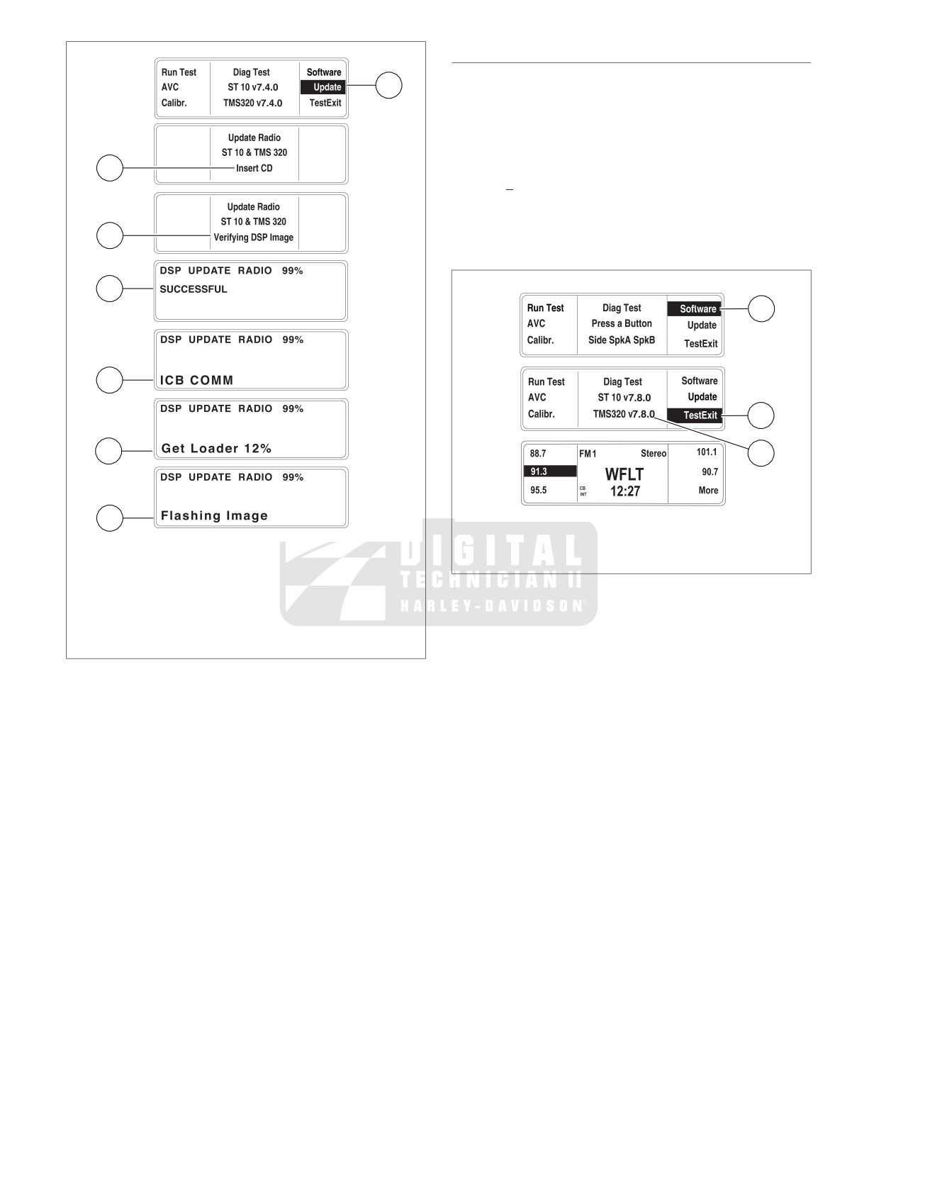
1. See Figure 8-40. In the Diag Test display, press the
GENERAL
Update (1) or number 5 soft key to open the Update Radio
The Advanced Audio receiver software will need to be updated
display.
after replacing the GPS navigation module or the receiver
2. To update the radio, follow the text prompt "Insert CD" (2),
module. The software will also need to be updated after receipt
and insert the replacement CD. The CD will automatically
of software revisions.
initiate the download. Updating the radio will take up to 7
OPENING DIAG TEST DISPLAY
minutes.
a. The text message, "Verifying DSP Image" (3), is dis-
NOTE
played as the percentage of download is updated.
The receiver should be in a radio (FM) mode prior to the
update.
b. An automatic power down and up, will proceed the
text message "SUCCESSFUL" (4).
1. Turn the ignition/headlamp key switch to OFF.
c. Sequentially, "ICB COMM" (5), "Get Loader" (6), and
2. Simultaneously press and hold any two soft keys (1, 2, 3,
"Flashing Image" (7), text messages will be displayed
4, 5, or 6).
as the percentage of download is updated.
3. Turn the ignition/headlamp key switch to ACCESS.
d. The receiver will again automatically power down and
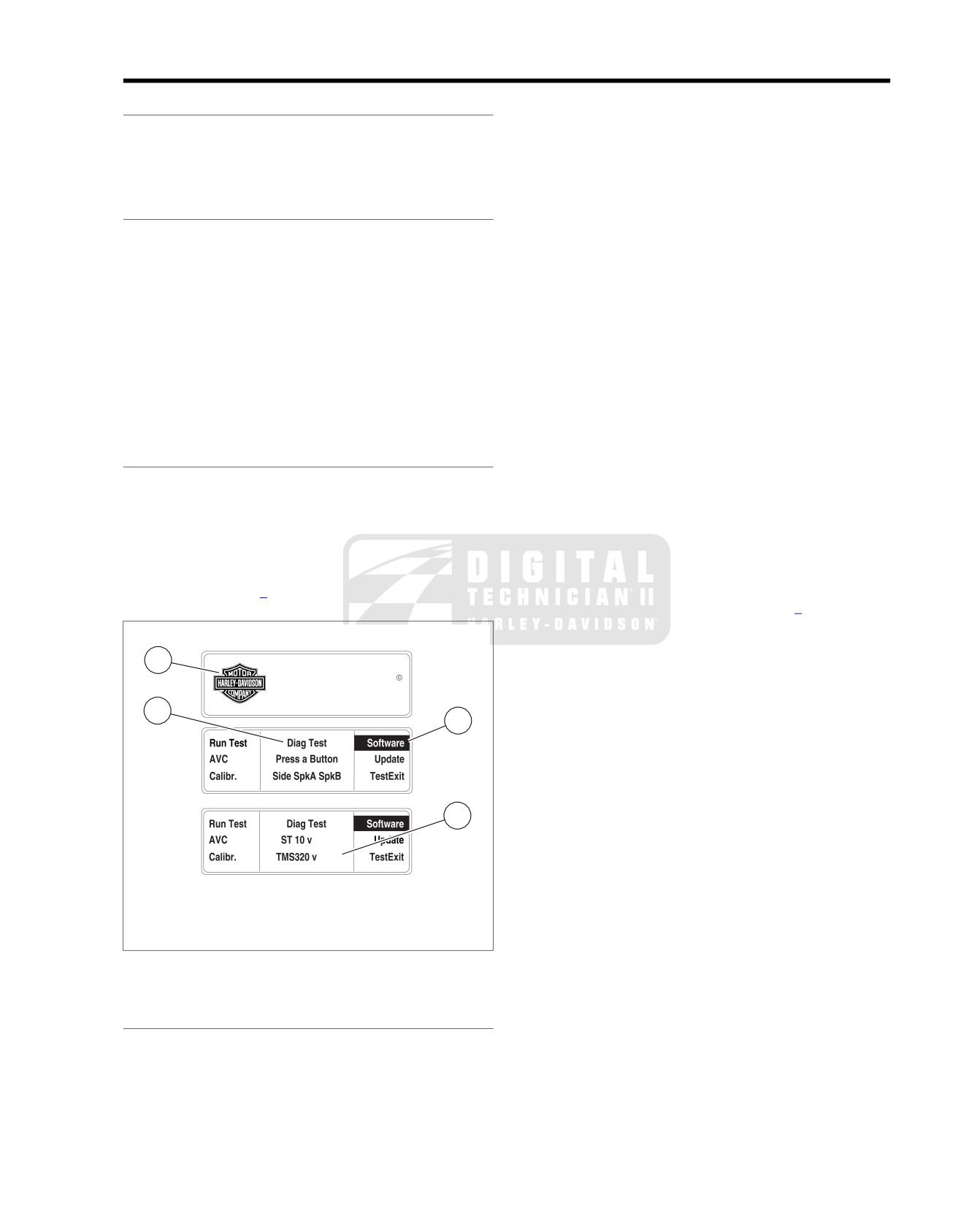
4. See Figure 8-39. Continue to hold the two soft keys while
up.
the Harley-Davidson Bar and Shield logo (1) is displayed.
NOTE
The display will cycle to Diag Test (2).
Should the CD not eject by pressing the eject button, turn the
IDENTIFYING VERSION NUMBER
radio OFF. Switch the ignition/headlamp key switch to OFF
and remove the maxi-fuse. Wait 5 minutes, install the maxi-
1. See Figure 8-39. In the Diag Test display, press the Soft-
fuse, turn the ignition knob to ACCESS and press the radio
ware or number 4 soft key (3) to display the software ver-
ON pushbutton. Wait for the Bar and Shield logo screen to
sion number.
close before attempting to eject the CD.
2. If the software version number (4) is lower than a disc
3. After the final automatic power down and up, press the
supplied with a replacement module or a disc received as
eject button to eject the CD. Remove the CD and close
a software update, update the software. See 8.12 RADIO
the CD door.
SOFTWARE UPDATE, Updating Receiver Software.
4. Proceed to 8.12 RADIO SOFTWARE UPDATE, Confirming
Version Number.
ed01611
1
advanced audio by
harman/kardon
2
3
4
7.4.0
7.4.0
1. Bar and Shield logo
2. Diag Test display
3. Software soft key 4
4. Software version number
Figure 8-39. Identify Software Version Number
UPDATING RECEIVER SOFTWARE
NOTE
Eject any CD. Leave the CD door open while the replacement
CD is in the reader.
2008 FLHTCUSE3 Service: Electrical 8-29
CONFIRMING VERSION NUMBER
ed01612
1. See Figure 8-41. In the Diag Test display, press the
1
"Software" (1) or number 4 soft key to display the software
version number (2).
2. Compare the displayed software version number to that
on the update CD. If the version number is different from
2
that supplied, start over at
8.12 RADIO SOFTWARE
UPDATE, Updating Receiver Software.
3. If both version numbers in the display match the update
CD, press the "TestExit" (3) or number 6 soft key. The
3
display will open to the current receiver mode.
ed01613
4
1
5
3
6
2
7
1. Software soft key 4
2. Software version number
1. Update soft key 5
3. TestExit soft key 6
2. Insert CD
3. Verifying DSP Image
Figure 8-41. Confirm Update Version Number
4. SUCCESSFUL
5. ICB COMM
6. Get Loader text
7. Flashing Image
Figure 8-40. Update Receiver Software
8-30 2008 FLHTCUSE3 Service: Electrical
ADVANCED AUDIO RADIO
8.13
REMOVING ADVANCED AUDIO
ed01614
NOTE
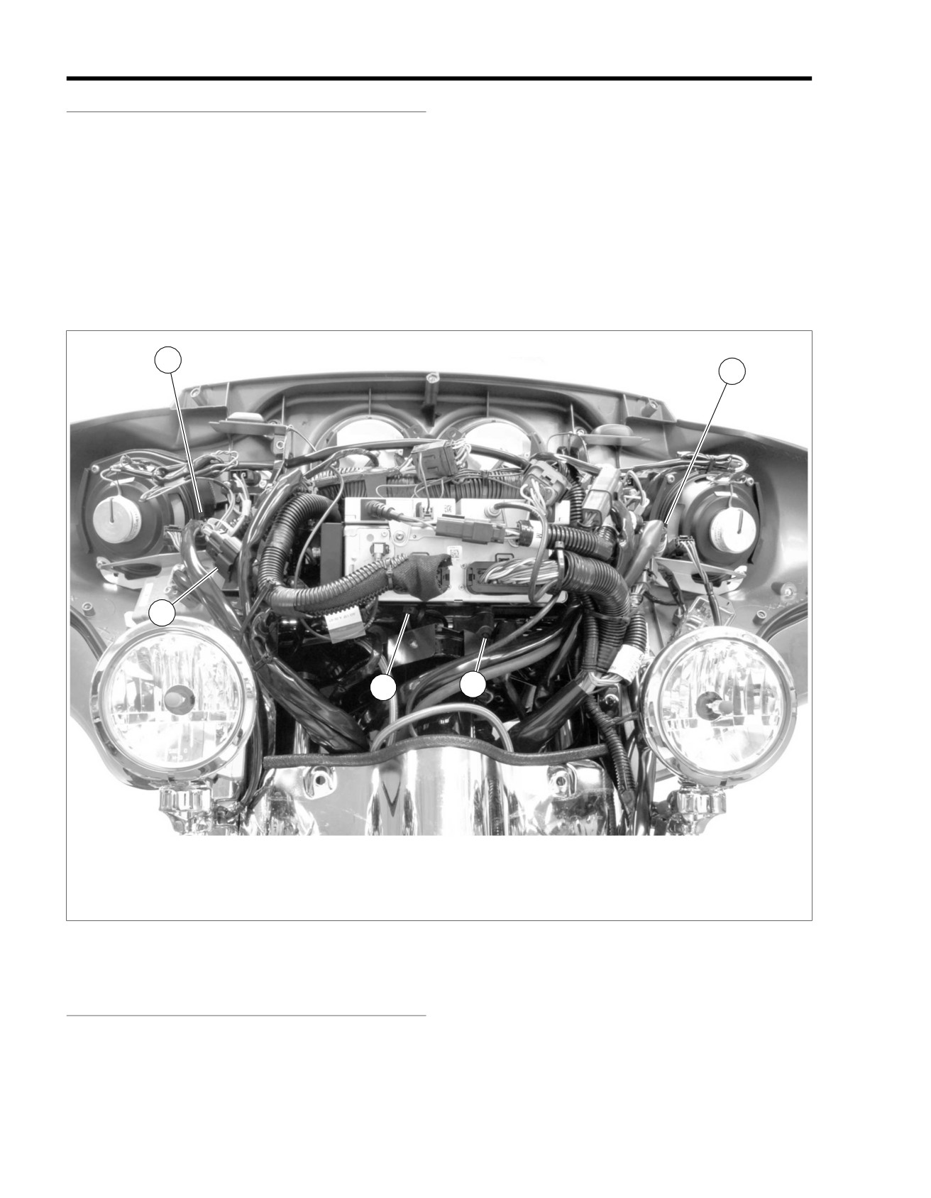
AM/FM/WB radio, CB transceiver, XM Satellite Radio module,
6
and the GPS Navigation module may all be removed as a unit.
2
1
1.
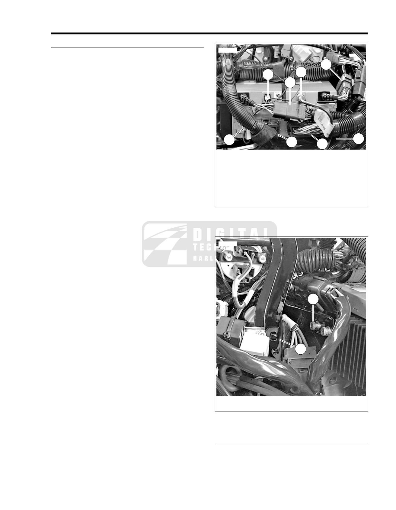
See Figure 8-42. Separate antenna connectors:
5
a. Depress latch and separate XM radio antenna cable
connector [185] (1). See 8.10 XM SATELLITE RADIO.
b. Depress latch and separate GPS Navigation antenna
connector [193] (3). See 8.11 GPS NAVIGATION.
c. Unscrew and remove CB radio antenna cable con-
nector [50] (2). See the ADVANCED AUDIO SYSTEM
in the Touring Models Service Manual.
4
3
7
8
d. Remove AM/FM/WB receiver antenna connector [51]
(4) by grasping ribbed plug and pulling straight out
1. XM antenna connector [185]
from radio. See the ADVANCED AUDIO SYSTEM in
2. CB antenna connector [50]
the Touring Models Service Manual.
3. GPS Navigation antenna connector [193]
4. AM/FM/WB antenna connector [51]
2.
Separate module connectors:
5. XM module 12-pin connector [185]
6. CB transceiver 12-pin connector [184]
a. Depress latches on either side of XM module 12-pin
7. AM/FM/WB radio 23-pin connector [27]
connector [185] (5) and separate connector.
8. AM/FM/WB radio 35-pin connector [28]
b. Depress latches on either side of CB transceiver 12-
Figure 8-42. Advanced Audio Connectors
pin connector [184] (6) and separate connector.
c. Depress latches on either side of AM/FM/WB radio
23-pin connector [27] (7) and 35-pin connector [28]
(8) and unplug connectors from receiver.
ed01615
3.
Locate cable strap with rosebud mount securing ignition
switch harness to bottom of radio chassis. Pull cable strap
mount from hole in chassis.
4.
See Figure 8-43. Unscrew and remove four screws with
captive washers (1), two on either side of radio chassis.
NOTE
1
Both screws on each side may be reached through tool access
slot (2).
5. Remove Advanced Audio Sound System assembly by
pulling straight forward and lifting up slightly after radio
bezel clears fairing.
6. If necessary, remove the CB, XM satellite, and GPS
modules.
2
1. Screw with captive washer (4)
2. Tool access slot
Figure 8-43. Sound System Mounting
INSTALLING ADVANCED AUDIO
1. If removed, install the CB, XM satellite, and GPS modules.
2008 FLHTCUSE3 Service: Electrical 8-31
2. See Figure 8-43. Slide sound system assembly into place
5. Mate Advanced Audio System connectors to modules:
in fairing.
a. XM module 12-pin connector halves (5).
3. Secure with four screws with captive washers (1), two on
b. Plug in CB transceiver 12-pin connector halves (6).
either side of radio chassis. Tighten to 35-45 in-lbs (4.0-
5.1 Nm).
c. Plug 23-pin connector (7) and 35-pin connector (8)
into radio.
4. See Figure 8-42. Locate cable strap with rosebud mount
attached to ignition switch harness. Plug cable strap mount
6. Plug in antenna connectors:
into hole in bottom of chassis.
a. AM/FM/WB antenna cable connector (4).
b. CB antenna cable connector (2).
c. XM antenna cable connector (1).
d. GPS antenna connector (3).
8-32 2008 FLHTCUSE3 Service: Electrical
ADVANCED AUDIO AMPLIFIER
8.14
GENERAL
ed01617
The Advanced Audio High-Output Amplifier is located under
the Tour-Pak and can be replaced without removing the Tour-
Pak from the vehicle.
REMOVAL
1. Turn ignition switch OFF.
NOTE
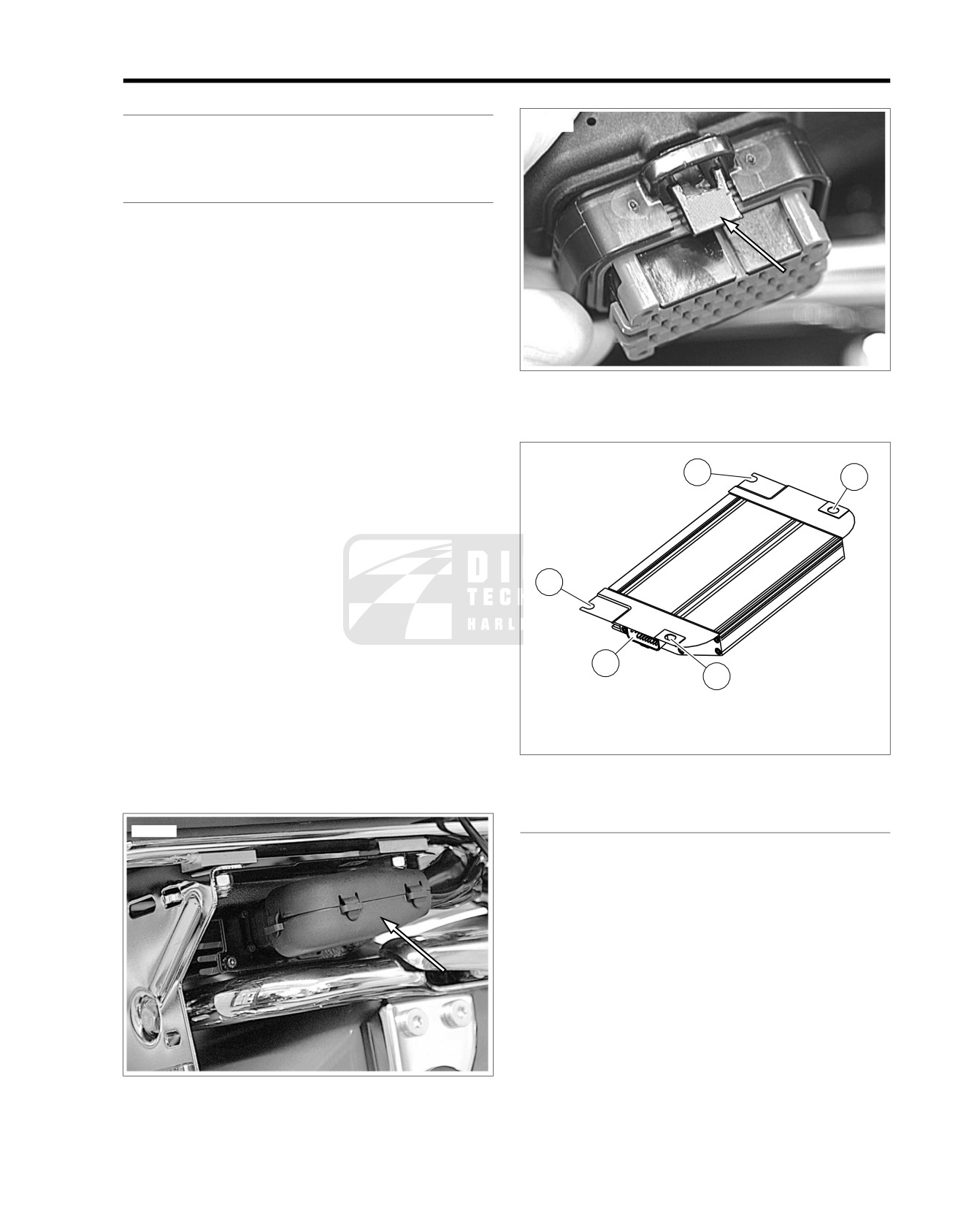
See Figure 8-45. Under the connector, use a flat blade screw-
driver to pull the latch down to release the connector [149].
2. See Figure 8-44. Unplug wiring harness connector [149]
from amplifier.
3. Open Tour-Pak and remove liner.
NOTES
•
Do not remove four bolts from the Tour-Pak until it is called
Figure 8-45. Connector [149] Release Latch
out in a numbered procedure.
•
Do not remove or loosen the rearmost locknut. This will
hold the Tour-Pak in place while replacing the amplifier.
ed01618
4. To protect finish, place a clean shop cloth between the
2
3
fender and amplifier.
NOTE
See Figure 8-46. Amplifier has two closed holes (3) in mounting
flange toward front of vehicle, and two open slots (2) toward
rear.
2
5. See Figure 8-48. Remove two nylon cap locknuts (1) and
flat washers (2) from two forward Tour-Pak mounting
positions.
6. Loosen, but do not remove, nylon locknuts from two rear
mounting locations. Do not remove center-rear locknut
1
3
(5).
7. Push two forward-most mounting bolts (7) up to clear the
1. Connector [149] pin housing
front amplifier mounting holes.
2. Rear mounting slots
3. Front mounting holes
8. Carefully slide amplifier toward front of motorcycle enough
to clear two rear mounting bolts and license plate bracket.
Figure 8-46. Amplifier
Slide amplifier out right side of motorcycle.
INSTALLATION
ed01616
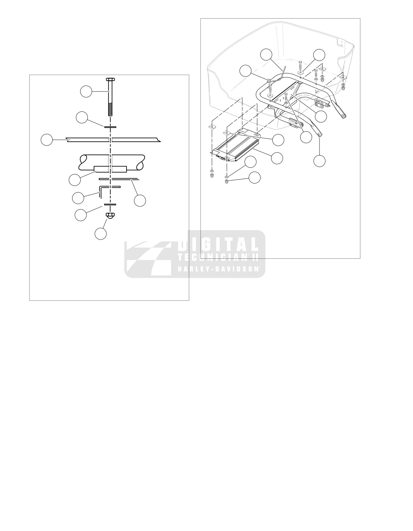
1. See Figure 8-47. Engage slots in rear of amplifier mounting
flange with rear mounting bolts (1), with amplifier flange
(5) between spacer (4) and license plate bracket (6).
2. See Figure 8-48. Place spacers (4) (concave side up)
between amplifier flange and top support tube (10) in the
forward mounting locations, aligning them with mounting
holes in Tour-Pak bottom.
3. Install forward bolts (7) with washers (8) through Tour-Pak,
top support tube, spacers and amplifier front mounting
flange.
4. Install washer (2) and nylon locknut (1) on each mounting
bolt.
NOTE
Figure 8-44. Amplifier Connector [149]
Make sure that concave section of each spacer remains in line
with top support tube rail and does not rotate out of position.
2008 FLHTCUSE3 Service: Electrical 8-33
5. In a crosswise pattern, alternately tighten mounting bolts
ed01620
and locknuts to 96-108 in-lbs (10.8-12.2 Nm).
6. Plug wiring harness connector [149] into amplifier socket.
7. Install liner in Tour-Pak.
6
8
8. Test sound system for proper operation.
5
ed01619
1
2
9
7
3
4
3
2
10
1
4
1. Locknut
2. Washer
6
5
3. Amplifier
4. Spacer (4)
7
5. Center-rear locknut
6. Antenna ground lead
7. Bolt
8
8. Large washer
1. Bolt
9. License plate bracket
2. Washer
10. Top support tube
3. Tour-Pak bottom
Figure 8-48. Tour-Pak/Amplifier Components
4. Spacer
5. Amplifier bracket
6. License plate bracket
7. Washer
8. Locknut
Figure 8-47. Fastener Stack
8-34 2008 FLHTCUSE3 Service: Electrical
GARAGE DOOR OPENER
8.15
TRANSMITTER
RECEIVER
Removal
Installation
1. Remove MAXIFUSE.
1. Unplug power cord from garage door drive unit to prevent
door activation during installation.
2. Remove outer fairing. See Touring Models Service Manual.
2. Find an unswitched 110V power outlet in garage that is
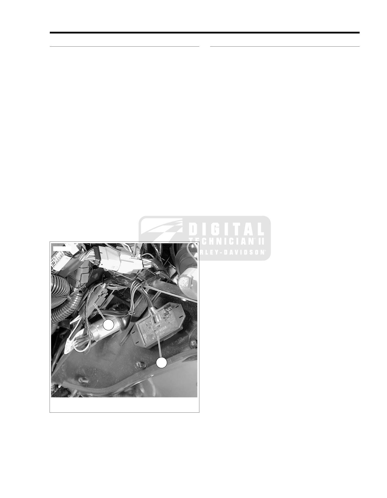
3. See Figure 8-49. Locate transmitter (1) on inner left side
located either highest in the garage, or closest to front of
of fairing.
garage, or both. Locate the Harley-Davidson remote-con-
4. Disconnect wiring harness connector [132+] (2).
trol garage-door opener receiver here.
5. Remove transmitter from adhesive tape mount.
NOTE
With some brands of garage door opener systems, it may be
Installation
necessary to plug in the Harley-Davidson receiver at a location
some distance away from the door opener. If the Harley-
NOTE
Davidson receiver is plugged in too close to the original opener
Be certain to apply pressure to adhesive tape when installing
receiver, effective transmission range may be significantly
transmitter.
reduced on both systems.
1. Clean surface with isopropyl alcohol and allow to dry.
3. Find two garage-door-activation switch terminals at one
Apply new transmitter.
of these locations:
2. Connect wires to harness.
a. The existing wall-mounted, hard wired garage door
opener button.
3. Verify correct function by verifying that the LED light on
transmitter blinks when the high-low beam switch is
b. The garage-door drive unit to which the garage-door-
activated.
opener button is connected.
4. Install outer fairing according to procedure in Touring
4. Fasten stripped end of Harley-Davidson garage-door
Models Service Manual.
opener receiver wires to door-opener terminals that
activate door opener drive unit. Refer to door-opener
5. Install MAXIFUSE.
manufacturer's documentation for terminal locations and
connections.
ed01621
NOTE
Do not remove original wires from original connections on the
door-opener button or on drive-unit terminals.
5. Assemble and install garage-door opener button in its
original location.
6. Route the plug end of the Harley-Davidson garage-door
opener wires to the Harley-Davidson garage-door opener
receiver location.
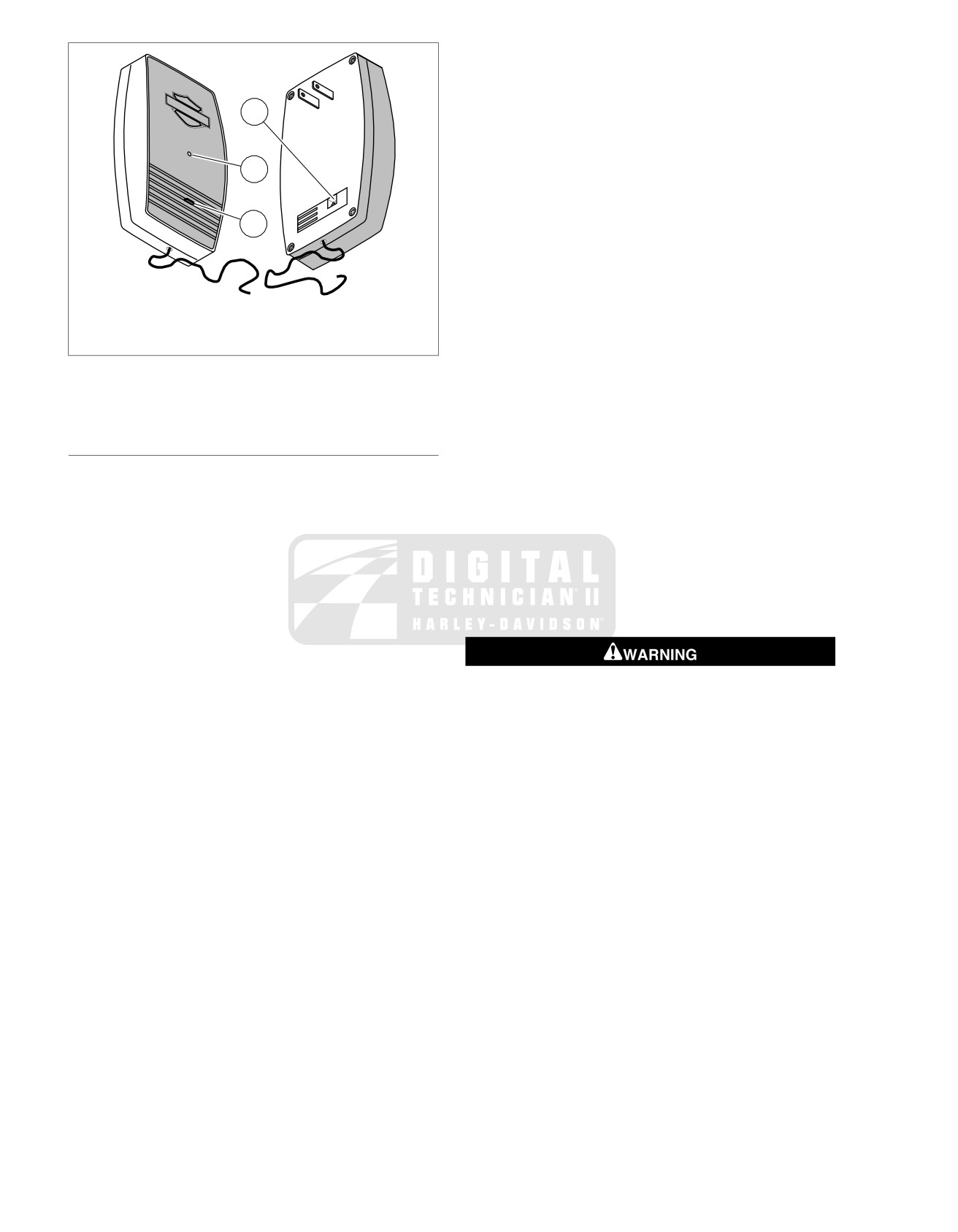
7. See Figure 8-50. Plug connector on Harley-Davidson
garage-door opener receiver wires into the receptacle (1)
2
back of Harley-Davidson garage-door opener receiver.
8. Plug garage-door opener receiver into selected power
outlet.
9. Plug power cord from garage-door drive unit into power
1
outlet.
10. Press wall-mounted garage-door-opener button to test
button operation.
1. Transmitter
2. Connector [132+]
Figure 8-49. Garage Door Opener Transmitter
2008 FLHTCUSE3 Service: Electrical 8-35
try to correct the interference by one or more of the following
ed01622
measures.
•
Reorient or relocate the receiving antenna.
1
•
Increase the distance between the equipment and the
receiver.
•
Connect the equipment to an outlet on a circuit different
2
from that to which the receiver is connected.
•
Consult the dealer or an experienced radio/TV technician
for help.
3
Program the Receiver and Transmitter
The receiver must be programmed to receive the transmitter
frequency. This process may require two people, depending
on how far apart the receiver and transmitter are during the
1. Wire connector/plug receptacle
programming process.
2. LED
3. Set button
1. Check that a red light is visible on the front of the Harley-
Davidson garage door opener receiver, indicating power
Figure 8-50. Garage Door Opener Receiver: FLHTCUSE3
to the receiver.
2. See Figure 8-50. Press and hold the Set button (3) the
REMOTE CONTROL GARAGE DOOR
Harley-Davidson garage door opener receiver. The LED
(2) blinks continuously while the Set button is pressed.
OPENER
3. Set the motorcycle ignition switch to IGN. Switch the
FCC Notices
headlamp beam switch using one of these sequences:
NOTE
a. Starting from Low beam, switch High, then Low.
Changes or modifications to this unit not expressly approved
b. Starting from high beam, switch Low, then High.
by the manufacturer could void the user's authority to operate
the equipment.
NOTE
When the receiver receives a signal from the transmitter, the
This equipment has been tested and
found to comply with the
LED on the transmitter turns off.
limits for Class B digital devices pursuant to Part 15, Subpart
B of the FCC Rules. These limits are designed to provide
4. Release the Set button on the receiver.
reasonable protection against harmful interference in a resid-
ential environment. This equipment generates, uses, and can
radiate radio frequency energy, and if not installed and used
in accordance with the instruction manual, may cause harmful
Be sure that all lights and switches operate properly before
interference to radio communications. However, there is no
operating motorcycle. Low visibility of rider can result in
guarantee that interference will not occur in a particular
death or serious injury. (00316a)
installation. If this equipment does cause harmful interference
NOTE
to radio or television reception, which can be determined by
Clear all obstructions away from between the transmitter and
turning the equipment off and on, the user is encouraged to
receiver before testing the operation of the garage door opener.
5. Test the garage door opener, high beam, and low beam
headlamp operation.
NOTE
When the transmitter is activated by toggling the headlamp
switch, the red LED on the transmitter illuminates for one
second to indicate that the transmitter is functioning correctly.
6. Turn the motorcycle ignition switch OFF.
8-36 2008 FLHTCUSE3 Service: Electrical
AUTOMATIC COMPRESSION RELEASE
8.16
GENERAL
ed01625
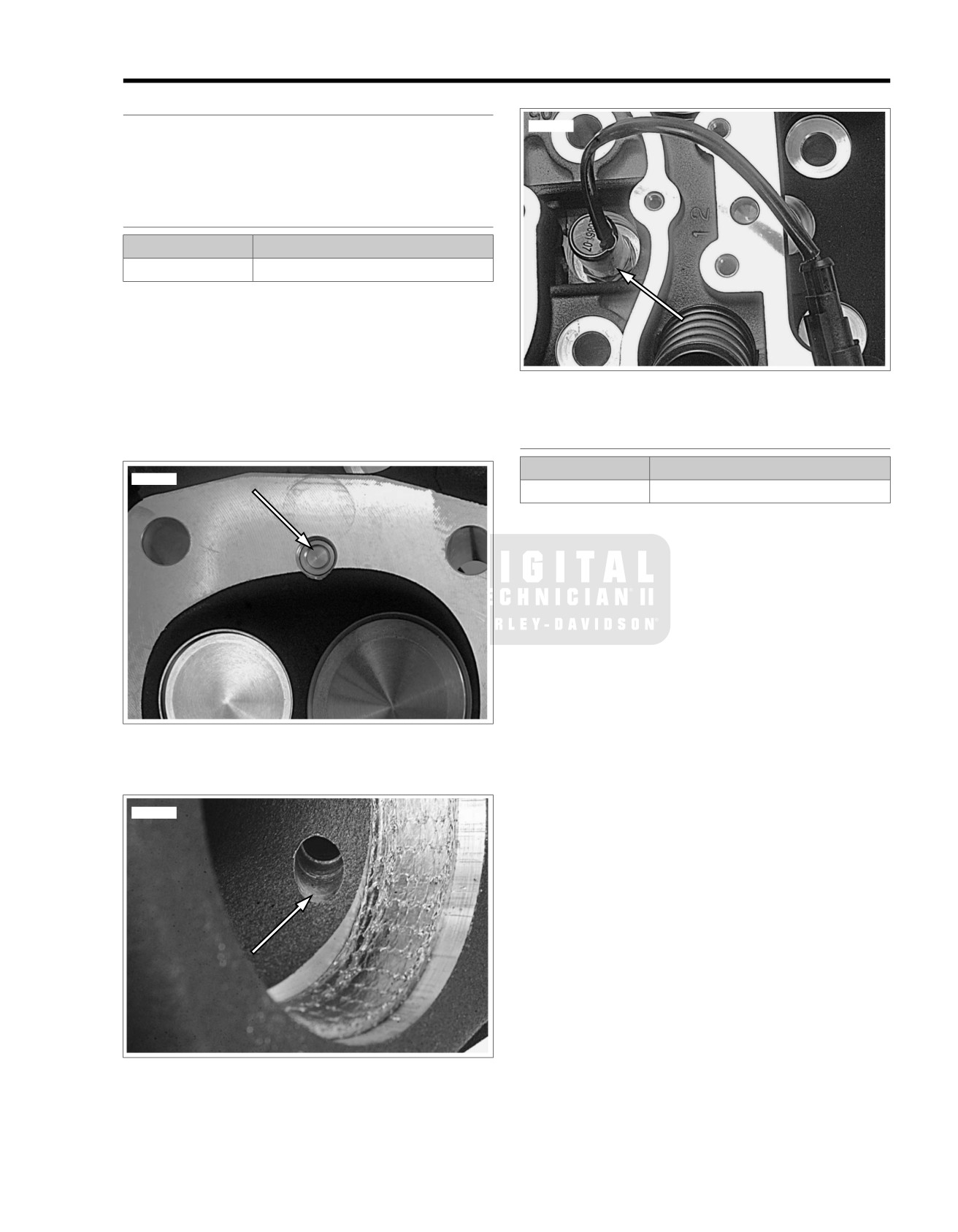
See Figure 8-51. The Automatic Compression Release (ACR)
is opened and closed by the ECM to assist starting.
See Figure 8-52. When open, compressed gases are released
through the exhaust port.
REMOVAL
PART NUMBER
TOOL NAME
HD-48498
ACR SOLENOID SOCKET
1. While preparing motorcycle for service, separate the ACR
rear [203R] and front [203F] connectors from the main
wiring harness.
2. Remove the rocker cover and the rocker box. See
STRIPPING MOTORCYCLE FOR SERVICE and TOP
END OVERHAUL in the Service Manual for procedures.
Figure 8-53. ACR in Head
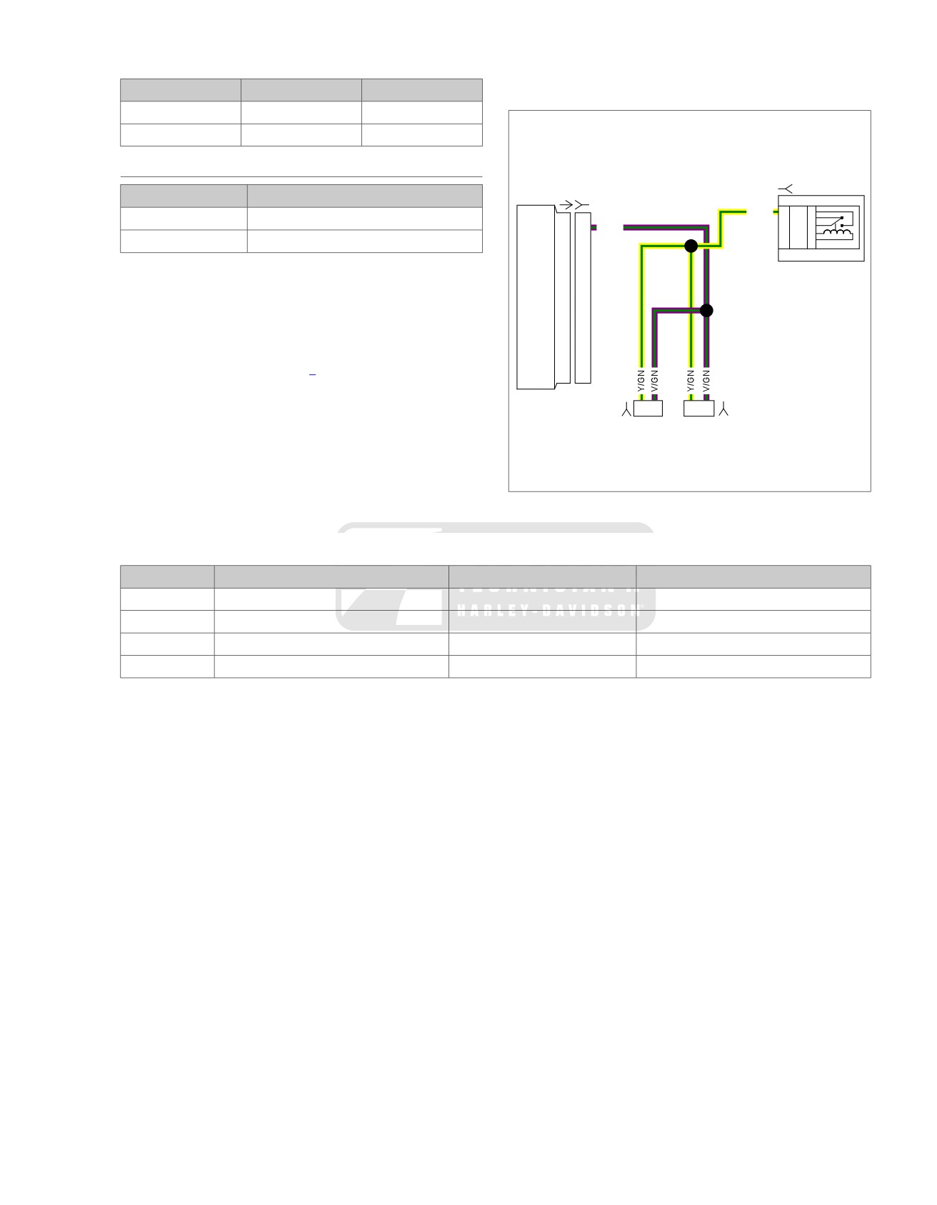
3. See Figure 8-56. Use ACR SOLENOID SOCKET (Part
No. HD-48498) to remove the ACR from the cylinder head.
INSTALLATION
PART NUMBER
TOOL NAME
ed01623
HD-48498
ACR SOLENOID SOCKET
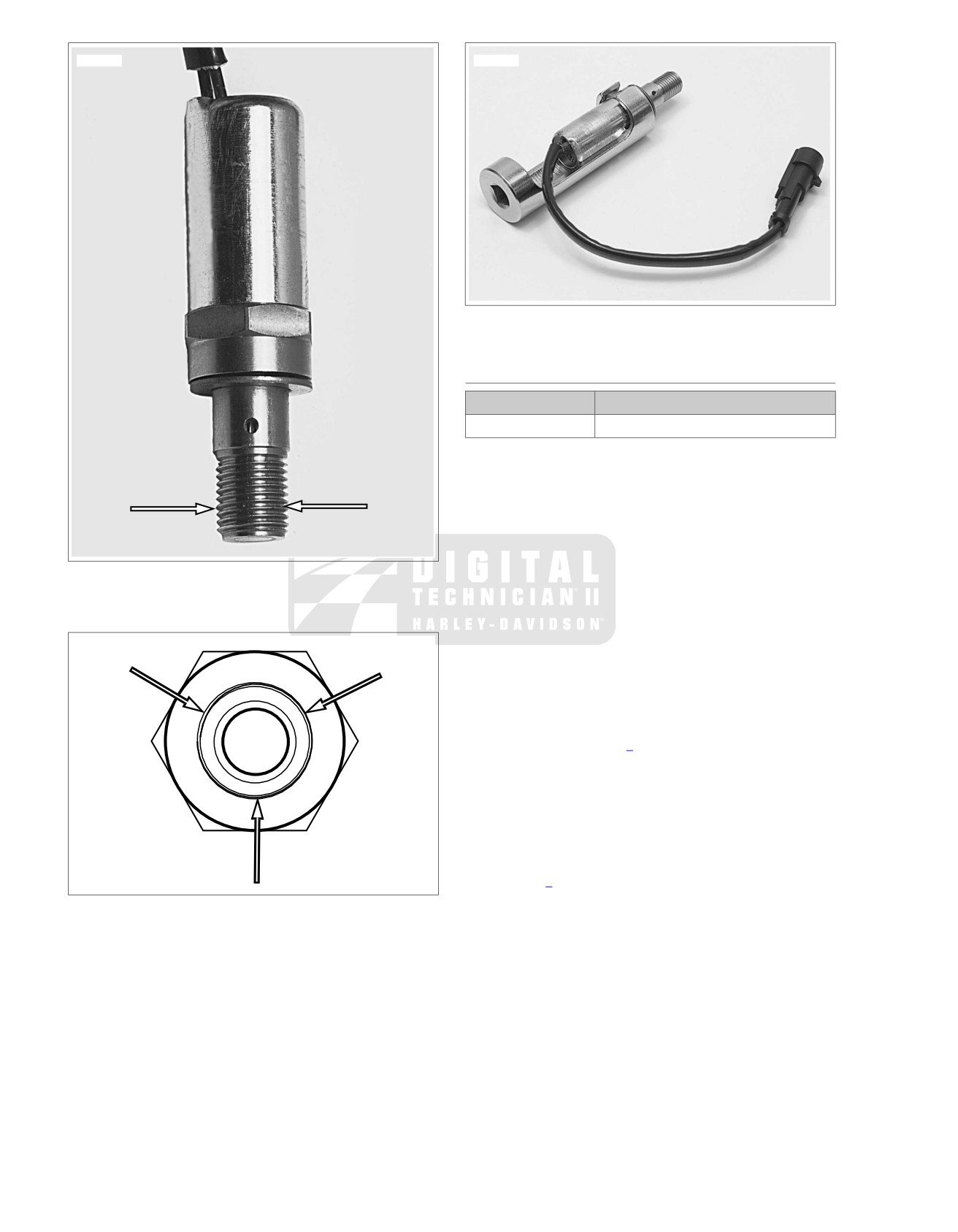
1. Verify that the copper seal washer is in place on the ACR.
2. See Figure 8-54. Identify a location around the threads of
the ACR approximately 1/3 of the way up from the end.
3. See Figure 8-55. Apply three equally spaced dots of
LOCTITE 246 THREADLOCKER MEDIUM STRENGTH
/ HIGH TEMPERATURE (blue) on threads.
4. To prevent cross threading, install and finger tighten.
5. See Figure 8-56. Using ACR SOLENOID SOCKET (Part
No. HD-48498), tighten to 11-15 ft-lbs (14.9-20.3 Nm).
6. Before installing the rocker box on each cylinder head,
route the wire harness toward the inside of the cylinder V.
Figure 8-51. ACR Valve in Combustion Chamber
7. With rocker boxes installed and the engine in the chassis,
mate the ACR connectors [203R] and [203F] to the corres-
ponding socket housings on the main wiring harness.
ed01624
Figure 8-52. ACR Exhaust Port Release
2008 FLHTCUSE3 Service: Electrical 8-37
ed01626
ed01628
Figure 8-56. ACR Solenoid Socket (HD-48498) and ACR
COMPRESSION TEST
PART NUMBER
TOOL NAME
HD-33223-1
CYLINDER COMPRESSION GAUGE
A compression test can determine the source of cylinder
leakage. Use CYLINDER COMPRESSION GAUGE (Part
No. HD-33223-1) with a screw-in type adapter.
NOTE
The Twin Cam 110 Engine uses a 12 mm adapter with the
compression gauge.
Figure 8-54. Bottom Third
1. Operate engine to normal operating temperature.
2. Disconnect spark plug wires.
3. Clean around plug base and remove front cylinder spark
plug.
ed01627
4. Install compression tester to front cylinder per gauge
instructions.
NOTE
The test results will vary depending on whether the ACR is
connected or not. Refer to Table 8-10 for specifications.
5. Shift transmission to neutral. Crank engine continuously
through 5 to 7 compression strokes.
6. Record gauge readings at the end of the first and last
compression strokes (highest readings).
7. Replace front spark plug and repeat test on rear cylinder.
8. Refer to Table 8-10. Readings should be within specified
range. If readings are higher than normal, suspect a
Figure 8-55. Three Dots of Loctite 246 Medium
compression release that is not functioning correctly. If
Strength/High Temperature
readings are low, inject approximately
1/2 oz. (15 ml)
engine oil into each cylinder and repeat the compression
tests on both cylinders.
NOTE
Readings that are considerably higher after injecting the oil
indicate worn piston rings.
8-38 2008 FLHTCUSE3 Service: Electrical
3. If V/GY wire is shorted to ground, the ACR's will remain
Table 8-10. Compression Specifications
on for a time that exceeds the design parameters and the
ACR solenoids will fail.
ACR STATUS
PSI
kN/m2
Connected
130-170
896-1,173
em00235
Disconnected
200-220
1,379-1,517
DIAGNOSTICS
[119B]
PART NUMBER
TOOL NAME
[78A] [78B]
Y/GN
K
87
5
HD-41404-B
TEST CONNECTOR KIT
T
87A
4
ACR
19
19
V/GN
E
30
3
S
85
2
HD-48637
BREAK-OUT BOX
U
86
1
Diagnostic Tips
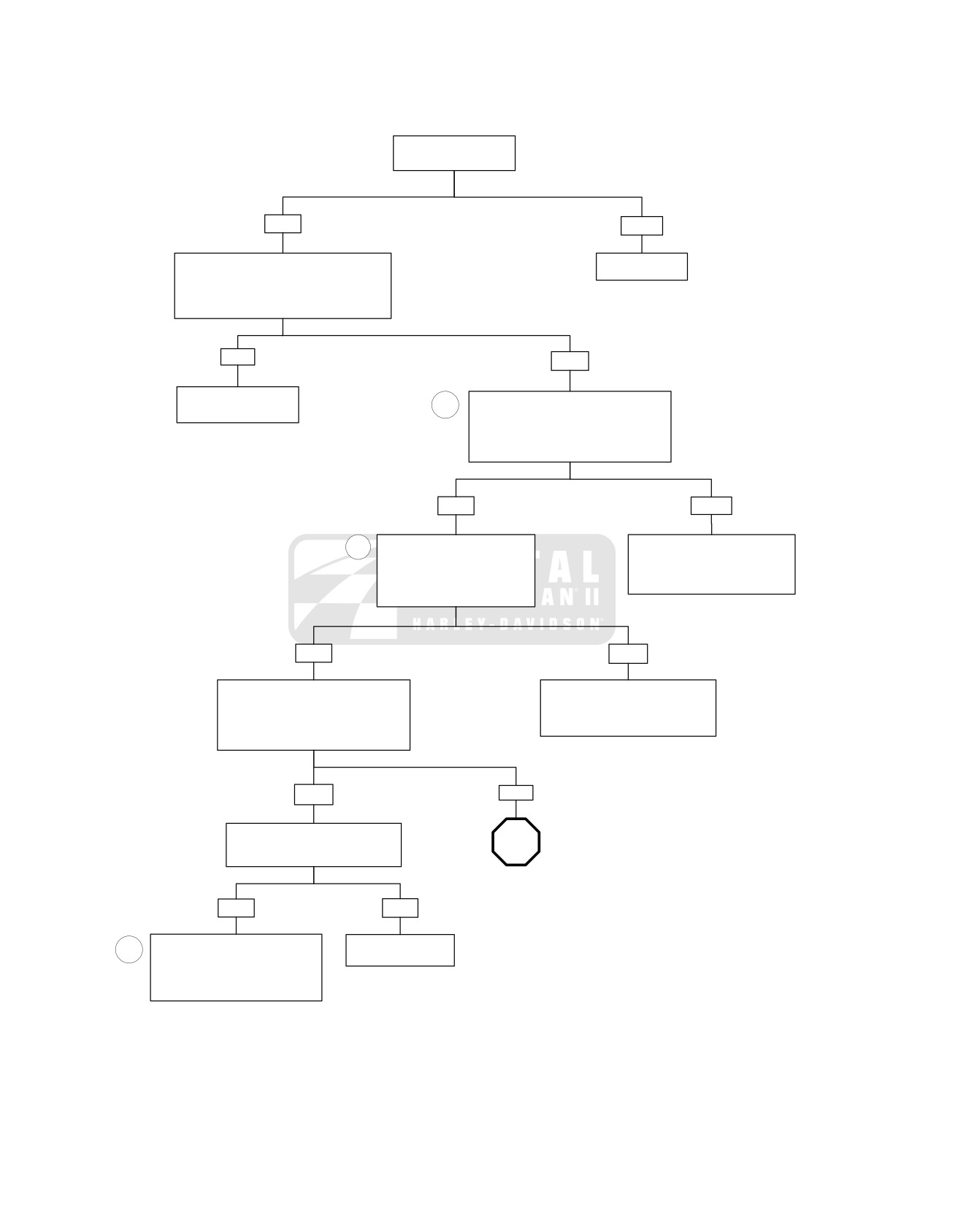
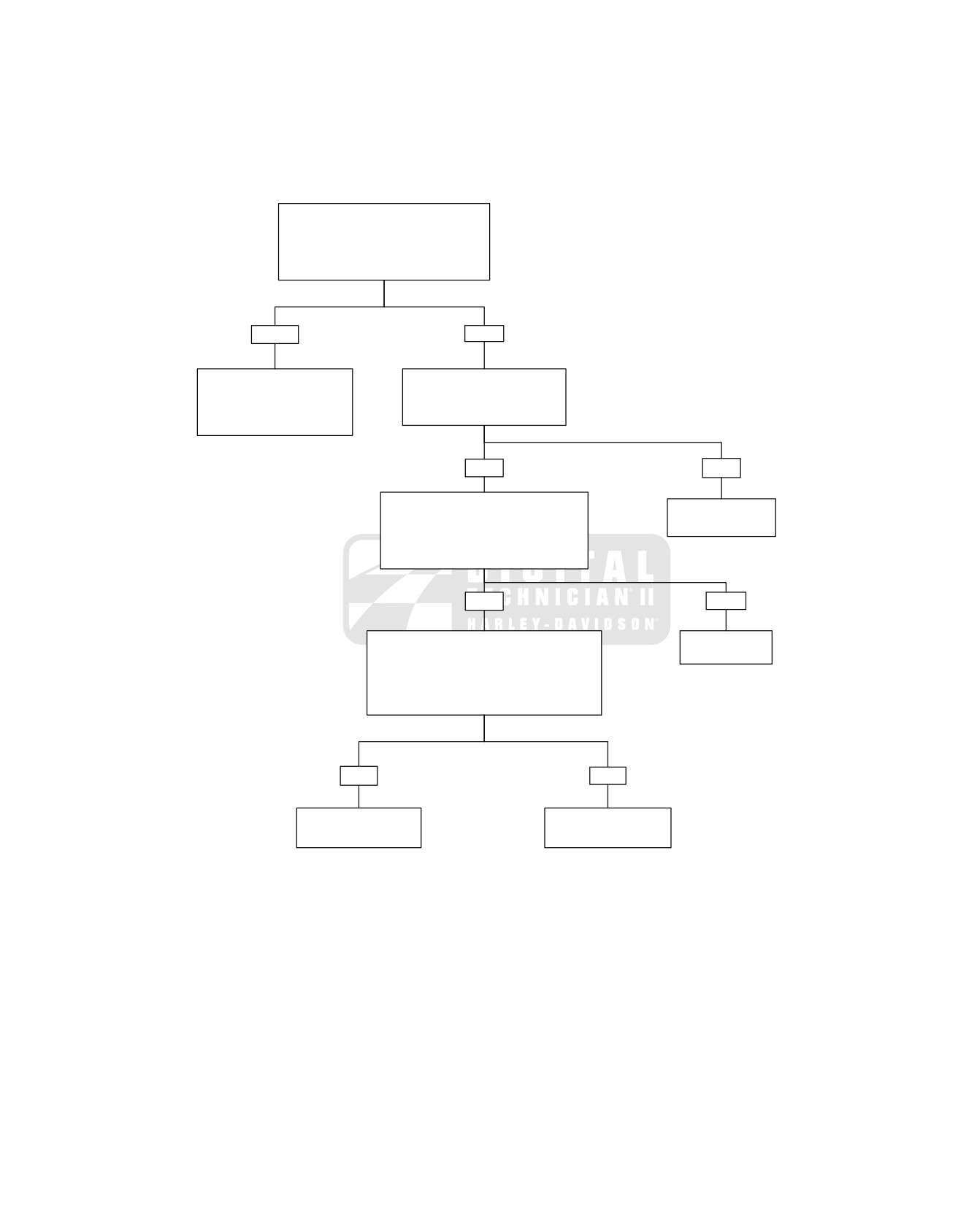
Refer to flow charts that follow for troubleshooting.
Diagnostic Notes
NOTES
•
The reference numbers in Table 8-11 correlate with the
circled numbers in Figure 8-57.
1
2
1
2
•
The step numbers below correlate with the circled numbers
[203FB]
[203RB]
in the flow chart.
1. Use TEST CONNECTOR KIT (Part No. HD-41404-B) with
gray terminal probes and patch cords.
2. Connect BREAK-OUT BOX (Part No. HD-48637) to ECM.
Figure 8-57. ACR Circuit
Table 8-11. Connectors/Fuse in ACR Circuit
NUMBER
DESCRIPTION
TYPE
LOCATION
[78]
ECM
73-place Delphi
Under seat
[203F]
ACR
2-place Amp (T
yco)
Between cylinders
[203R]
ACR
2-place Amp (T
yco)
Between cylinders
[119]
System relay
Lugs
Fuse block
2008 FLHTCUSE3 Service: Electrical 8-39
ACR Diagnostics (Part 1 of 2)
Is battery voltage 12.6
VDC or higher?
YES
NO
Perform starter current draw test while cranking
Charge battery.
engine at room temperature. Remove system
relay and repeat starter current draw test.
Is current draw 20-40 Amps greater with
system relay removed?
YES
NO
Review symptoms.
1
During the first 2 seconds after turning the
Issue is not ACR related.
key on (while relay is energized) or while
cranking, measure voltage at terminal “1” on
connector [203FB] (front) or [203RB] (rear).
Is battery voltage present?
YES
NO
2
Measure continuity between
Locate and repair open on Y/GN
terminal “2” on connector [203FB]
wire between terminal “1” on
(front) or [203RB] (rear) and
connector [203FB] (front) or
breakout box terminal “19”.
[203RB] (rear) and system relay.
Is continuity present?
7077
YES
NO
Disconnect breakout box from ECM
Locate and repair open on V/GY wire
leaving harness connected to breakout
between terminal “2” on connector
box. Measure continuity between terminal
[203FB] (front) or [203RB] (rear) and
“19” on breakout box and ground.
ECM connector [78B] terminal “19”.
Is continuity present?
7076
YES
NO
Disconnect connector [203FB] (front)
and [203RB] (rear) one at a time.
STOP
Is continuity to ground still resent?
Go to
ACR Diagnostics
(Part 2 of 2).
YES
NO
Locate and repair short to ground on
Replace grounded
3
V/GY wire between terminal “2” on
ACR.
connector [203FB] (front) or [203RB]
(rear) and ECM connector [78B}
7077
fc01777_en
terminal “19” and replace both ACRs.
7078
8-40 2008 FLHTCUSE3 Service: Electrical
ACR Diagnostics (Part 2 of 2)
Continued from ACR Diagnostics
(Part 1 of 2).
Measure voltage at breakout box terminal “19”
with breakout box disconnected from ECM.
Is voltage present?
YES
NO
Locate and repair short to voltage
Measure resistance between
on V/GY wire between terminal
terminal “1” and “2” on connector
“2” on connector [203FB] (front)
[203FA] (front) or [203RA].
or [203RB] (rear) and ECM
Is continuity present?
connector [78B] terminal “19”.
7079
YES
NO
Reconnect breakout box and ECM; and
ACRs to the engine wiring harness. Measure
Replace defective
voltage at terminal “19” during cranking.
ACR solenoid.
Is voltage 0.1-8.0 VDC and fluctuating while
7077
engine cranks?
YES
NO
Perform compression test (only one spark plug can
Replace ECM
be removed at a time or ACR will be disabled).
Refer to COMPRESSION TEST.
7080
Is compression 130 - 170 PSI (896- 1,173 kN/m2 0
with ACR connected and 200-220 PSI (1379-1517
kN/m2) with ACR disconnected?
YES
NO
Review symptoms. Issue
Replace ACR on cylinder
is not ACR related.
that is non-functional.
7077
fc01778_en
2008 FLHTCUSE3 Service: Electrical 8-41
TWIST GRIP SENSOR (TGS)
8.17
5. Remove terminals and wire leads from connector housing.
REMOVAL
See APPENDIX B, MOLEX and DEUTSCH ELECTRICAL
NOTE
CONNECTORS in Touring Models Service Manual.
The twist grip sensor also contains the leads for the handgrip
6. Securely attach a piece of mechanic's wire approximately
heater.
3 ft (1 m) long to the bundle of terminals using electrical
1. Remove outer fairing. See Touring Models Service Manual.
tape. This will be used as a harness leader.
2. Remove MAXIFUSE.
7. Remove the right handgrip. See Remove Right Handgrip
in 2.8 HANDGRIPS.
3. Remove cable ties as necessary.
8. Lubricate harnesses with glass cleaner, and carefully pull
4. See Figure 8-58. Disconnect twist grip sensor (TGS)
TGS from end of handlebar. Continue to pull until tape
connector [204] (5) and handgrip heater interconnect
securing wire leaders to harnesses can be removed.
harness connector [206] (4).
9. Remove leaders from harness terminals.
ed01629
5
1
2
4
3
1. Left handlebar switch connector [24]
2. Right handlebar switch connector [22]
3. Handgrip heater power connector [189]
4. Handgrip heater interconnect [206]
5. Twist grip sensor connector [204]
Figure 8-58. Handlebar Control Connector Locations
INSTALLATION
NOTES
•
Attach wire lead bundles to mechanic's wire to draw wire
leads back through handlebars, and out center of
8-42 2008 FLHTCUSE3 Service: Electrical
handlebar. Remove mechanic's wire carefully to avoid
9. Secure wire harnesses at exit from center of handlebar
damage to terminals.
with cable strap.
•
Liquid glass cleaner may be used to aid in pulling wires
10. See Figure 8-58. Mate twist grip sensor harness connector
through conduit.
[204] (5) and handgrip interconnect harness connectors
[206] (4). Secure interconnect harness connector assembly
•
As you pull on wire leader, assist the process by gently
to right switch control harness with cable tie.
feeding harnesses into handlebar at other end. If resist-
ance is felt, do not pull too hard on wire leader as this may
11. Install MAXIFUSE.
damage wires and/or terminals, or dislodge leader from
12. Install outer fairing.
harness.
13. Turn the Ignition/Light Key Switch to IGNITION and apply
1.
Wrap wires and terminals of each harness tightly with
brake lever to test operation of brake lamp.
electrical tape to protect wires and terminals when
installing harnesses in handlebar. Tape right handgrip
interconnect harness terminals to TGS harnesses.
Table 8-12. Twist Grip Sensor (TGS) Connectors
2.
Neatly wrap terminals and wires of TGS harness with a
INTERCONNECT [206]
TGS [204]
few twists of the leader wire. Attach wire leader to TGS
(2-WAY, BLACK)
(6-WAY, BLACK)
harness with electrical tape.
WIRE
TERMINAL
WIRE
CONDUIT
TERMINAL
3.
Lubricate wire conduits with glass cleaner.
COLOR
COLOR
COLOR
BK
1
BK
Y
1
4.
Gently pull harnesses through handlebar to draw twist grip
sensor into handlebar. Fit index tabs on twist grip sensor
BK/W
2
W
Y
2
into slots in handlebar. One index tab and slot are smaller
-
-
R
Y
3
than the others to prevent improper assembly.
-
-
BK
BK
4
5.
Install right hand grip, switch housings, and front master
-
-
W
BK
5
cylinder. See Install Right Handgrip in 2.8 HANDGRIPS.
-
-
R
BK
6
6.
Following color codes in Table 8-12, insert terminals into
numbered chambers in connector housings:
Reset TGS/ECM
NOTE
NOTE
See APPENDIX B in Touring Models
Service Manual for con-
Whenever a new twist grip sensor (or ECM) is installed, the
nector assembly guidelines.
relationship between
the TGS and ECM must be reset. As the
7. Gently tug on wire ends to verify that all terminals are
ECM uses the first four ignition cycles to establish the optimum
locked.
idle speed, there may be initial performance problems if the
procedure is not performed, such as high idle or hesitation
NOTE
when the throttle is opened.
Do not pull the switch housings so far inboard as to cause the
throttle grip to bind or drag on the handlebar. Rotate the throttle
Place the engine run/stop switch in the RUN position and turn
grip to verify that it freely returns to the idle position.
the ignition/light keyswitch to IGNITION and then back to OFF
four times (without starting engine), allowing at least three
8. Gently pull on wire harness to remove any excess slack
seconds to elapse between ignition cycles.
in harnesses. Remove tape and mechanic's wire.
2008 FLHTCUSE3 Service: Electrical 8-43
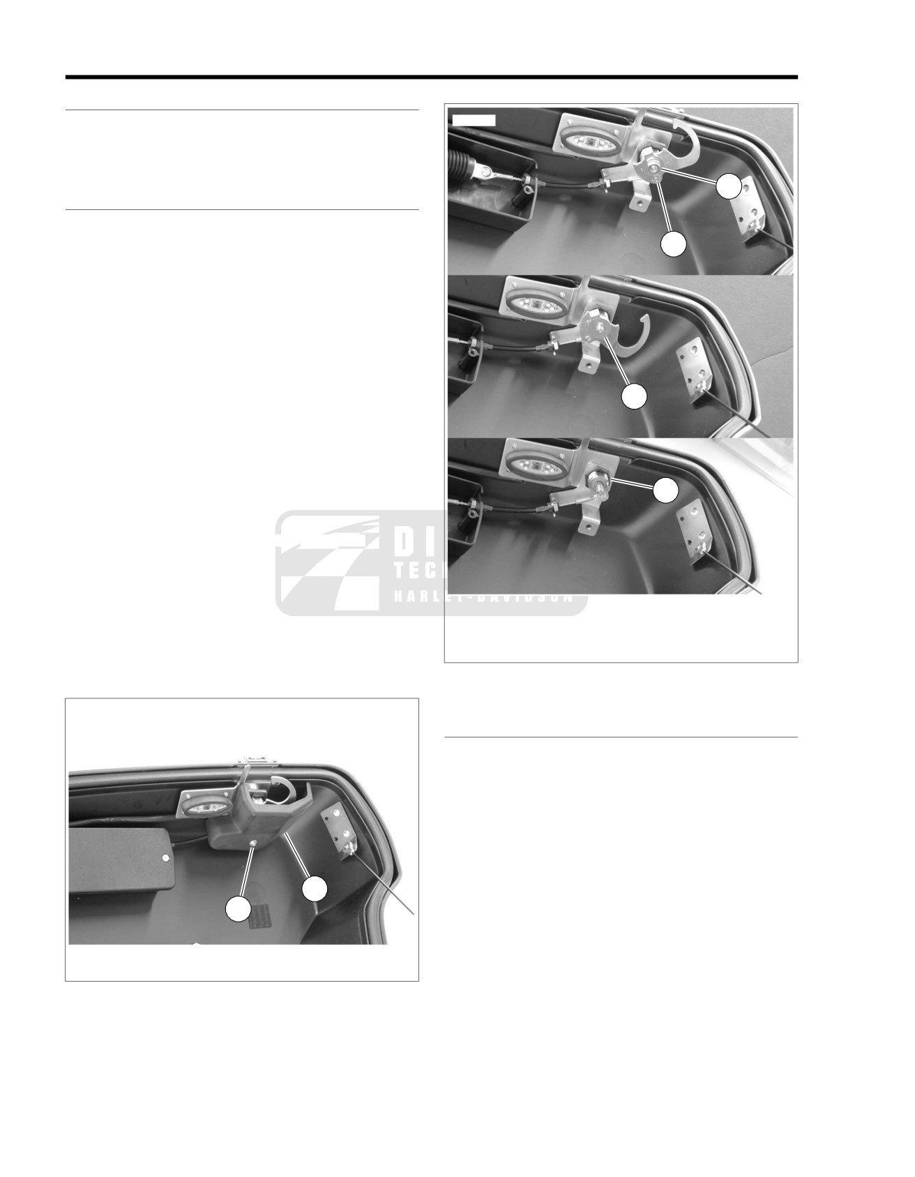
POWER LOCKS
8.18
GENERAL
ed01632
Power locks are installed on the Tour-Pak and on both
saddlebags. The cables and actuators can be replaced without
removing the protective box or the entire assemblies can be
removed and replaced.
2
POWER LOCK LOCKSET: TOUR-PAK
Removal
1
1. Remove the MAXIFUSE.
2. Remove the felt liner from Tour-Pak cover.
3. See Figure 8-59. Remove the fastener (1) holding the latch
cover in place.
4. See Figure 8-60. Remove retaining ring (1) and disconnect
cable end from latch.
5. Remove nut and washer (2).
3
6. Remove latch components (3).
7. Remove nut (4) and remove lockset from cover.
Installation
1. See Figure 8-60. Insert the lockset and install nut (4).
4
Tighten to 30-45 in-lbs (3.4-5.1 Nm).
2. Install latch components (3) and secure with nut and
washer (2). Tighten to 25-35 in-lbs (2.8-4.0 Nm)
3. Connect cable end to latch hook
and retain with retaining
ring (1).
4. See Figure 8-59. Install the latch cover and secure with
1.
Retaining ring
fastener (1).
2.
Nut and washer
3.
Latch components
5. Install felt liner.
4.
Nut
6. Install MAXIFUSE and test power lock operation.
Figure 8-60. Tour-Pak Lockset
ed01631
ACTUATOR: TOUR-PAK
Removal
NOTE
The actuator and/or cable can be replaced without removing
the protective box from the Tour-Pak.
1. Remove MAXIFUSE.
2. Remove upper and lower felt liners.
2
3. Separate the connector [213T] located in the Tour-Pak
1
bottom.
4. Remove the cover from the latch assembly.
1. Fastener
5. Remove two fasteners and remove the actuator box cover.
2. Latch cover
NOTE
Figure 8-59. Tour-Pak Latch Cover
To prevent locking the Tour-Pak without a release mechanism,
do not close the Tour-Pak cover until repairs are complete.
6. See Figure 8-61. Remove harness from retaining clips (1).
8-44 2008 FLHTCUSE3 Service: Electrical
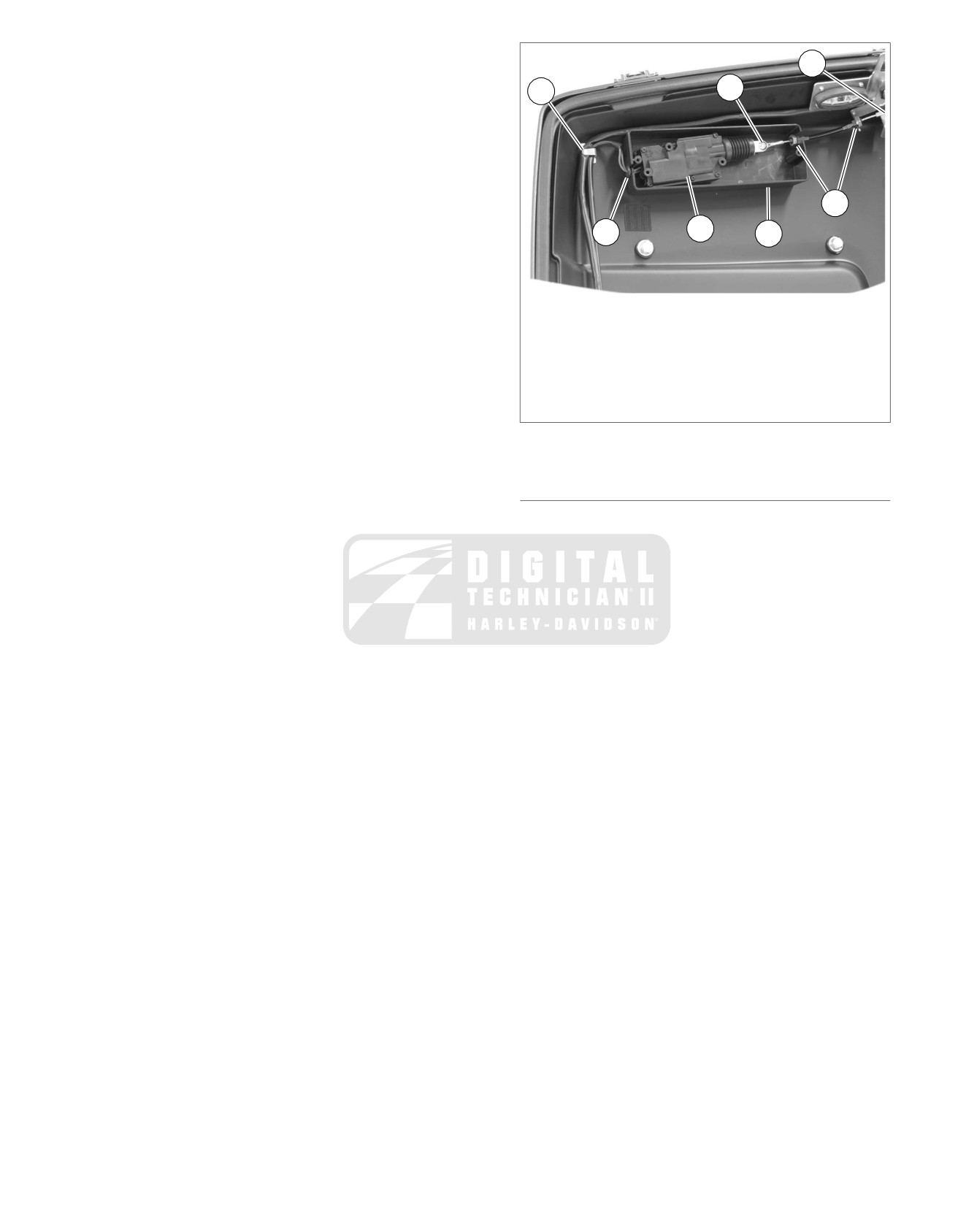
7. Remove retaining ring
(2) securing cable to latch
ed01633
assembly.
2
8. Loosen jam nut (3) from each end of cable. Remove cable
1
6
from latch bracket and actuator box slots.
9. Pull the actuator (4) off of its thin plastic mounting studs
while disengaging the harness and grommet (5) from the
actuator box.
10. Remove the fastener and locknut (6) from the end of the
3
actuator to remove the cable.
4
11. If necessary, remove the actuator box (7) from the inside
5
7
wall of the Tour-Pak cover.
Assembly
NOTE
1. Harness retaining clip
Be certain to apply pressure to adhesive tape when installing
2. Retaining ring, latch
actuator box.
3. Jam nuts
4. Actuator
1.
If removed, attach the actuator box to the inside of Tour-
5. Harness and grommet
Pak cover:
6. Fastener and locknut
a. See Figure 8-61. Clean mounting surface of Tour-Pak
7. Actuator box
with isopropyl alcohol. Allow to dry.
Figure 8-61. Tour-Pak Power Lock Actuator
b. Use double sided tape and mount actuator box (7) to
inside wall of Tour-Pak cover.
POWER LOCKS: SADDLEBAGS
2.
Assemble the cable to the end of the actuator with fastener
and locknut (6). Tighten securely.
Removal
3.
Slide the actuator (4) over the plastic mounting studs.
1. Remove the MAXIFUSE.
4.
Press the harness and grommet (5) into the slot
in the
2. Open the saddlebag and lift out the felt liner.
box.
3. Separate the power
lock connector [213] and remove the
5.
Slide the cable into the slots in the box and latch bracket.
saddlebag.
Tighten the jam nuts (3) securely.
4. Remove the wire terminals from the connector housing
6.
Install the actuator box cover.
and pull the wire leads through the cord grip exit hole in
the side of the saddlebag.
7.
Connect the cable to the latch assembly and secure with
retaining ring (2).
NOTES
8.
Route harness through retainers (1) and mate connector
•
Squeeze the cord grip together on the inside of the
[213T] to harness connector located in Tour-Pak bottom.
saddlebag and push the cord grip out.
9.
Install latch cover.
•
See APPENDIX B DEUTSCH ELECTRICAL CON-
NECTORS in the Touring Models Service Manual for
10.
Install felt liners.
connector service procedures.
11.
Install MAXIFUSE and test power lock operation.
5. Remove the two screws from the check strap and the latch
cover.
6. See Figure 8-62. Loosen the lock nut on the cable end
and remove the cable ball end from the latch inner cam.
If the inner cam and latch require service, see
2.16 SADDLEBAGS LATCH for procedures.
7. Remove harness from the retaining clips.
8. Remove the actuator box and harness from the bottom of
saddlebag.
Installation
1. Clean inside mounting surface of saddlebag with isopropyl
alcohol. Allow to dry.
2. Use double sided tape to fix box to mounting surface.
3. Slip barrel end of cable into saddlebag locking arm.
Assemble cable into slot on bracket. Tighten locknut.
2008 FLHTCUSE3 Service: Electrical 8-45
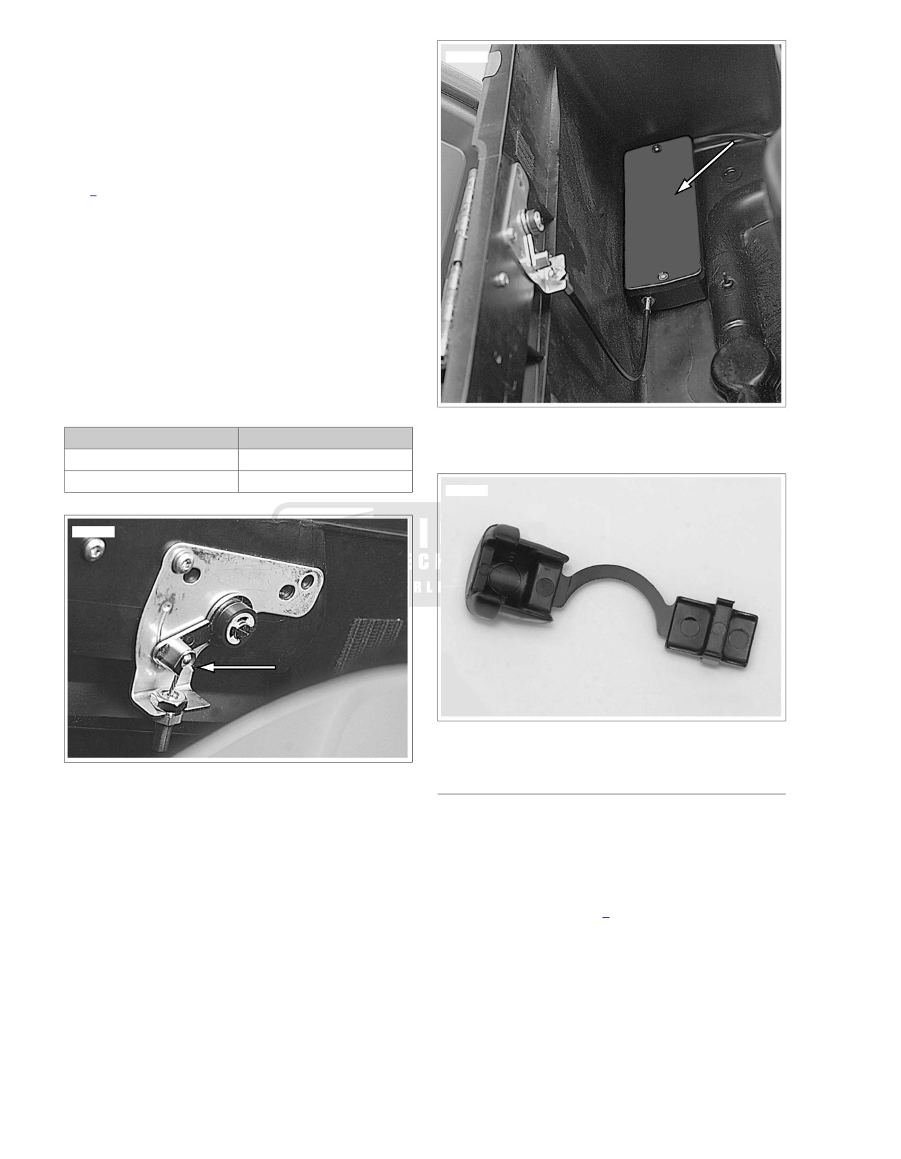
4. Thread wire leads through exit hole in side of saddlebag
ed01635
and under harness retaining clips. Replace clips if neces-
sary.
5. See Figure 8-64. Snap cord grip over the wire lead conduit
and press the small end of the cord grip into exit hole from
the outside of saddlebag.
6. Install terminals in connector housing. The cavity numbers
are embossed on the sides of the connector. Refer to
Table 8-13.
NOTE
See APPENDIX B DEUTSCH ELECTRICAL CONNECTORS
in the Touring Models Service Manual for connector service
procedures.
7. Mate power lock connector [213] halves while installing
the saddlebag.
8. Install latch cover. Tighten screws to 25 in-lbs (2.8 Nm).
9. Install felt liner.
10. Install MAXIFUSE and test power lock.
Table 8-13. Connectors [213R] and [213L]
Figure 8-63. Actuator Box
TERMINAL
WIRE LEAD COLOR
1
GN
2
BE
ed01636
ed01634
Figure 8-64. Cord Grip
Figure 8-62. Cable Ball End in Inner Cam
ACTUATOR: SADDLEBAG
Disassembly
NOTE
The actuator and/or cable can be replaced without removing
the protective box from the saddlebag.
1. To remove the actuator assembly from a saddlebag, see
8.18 POWER LOCKS, Power Locks: Saddlebags.
2. Remove two fasteners to open the actuator box cover.
3. Loosen the cable jam nut.
4. Pull the actuator off from its thin plastic mounting studs
and slide the grommet and wire leads out of the slot in the
box.
5. Remove the Torx head screw and lock nut from the end
of the actuator to remove the cable and elbow.
8-46 2008 FLHTCUSE3 Service: Electrical
4. Install the cable elbow in the slot in the box and tighten
Assembly
the locknut.
1. Fasten the cable eyelet over the actuator with the Torx
head screw and tighten the lock nut.
5. Install the cover with two fasteners.
2. Orient the actuator to the cable and grommet slots in the
6. Install the power lock assembly into the saddlebag. See
box, and slide the actuator over the plastic mounting studs.
INSTALL under 8.18 POWER LOCKS, Power Locks:
Saddlebags.
3. Press the wire lead grommet into the slot in the box.
em01300
Fuse
1E
2G
Block
P&A fuse
Power locks
15A
15A
1F
2H
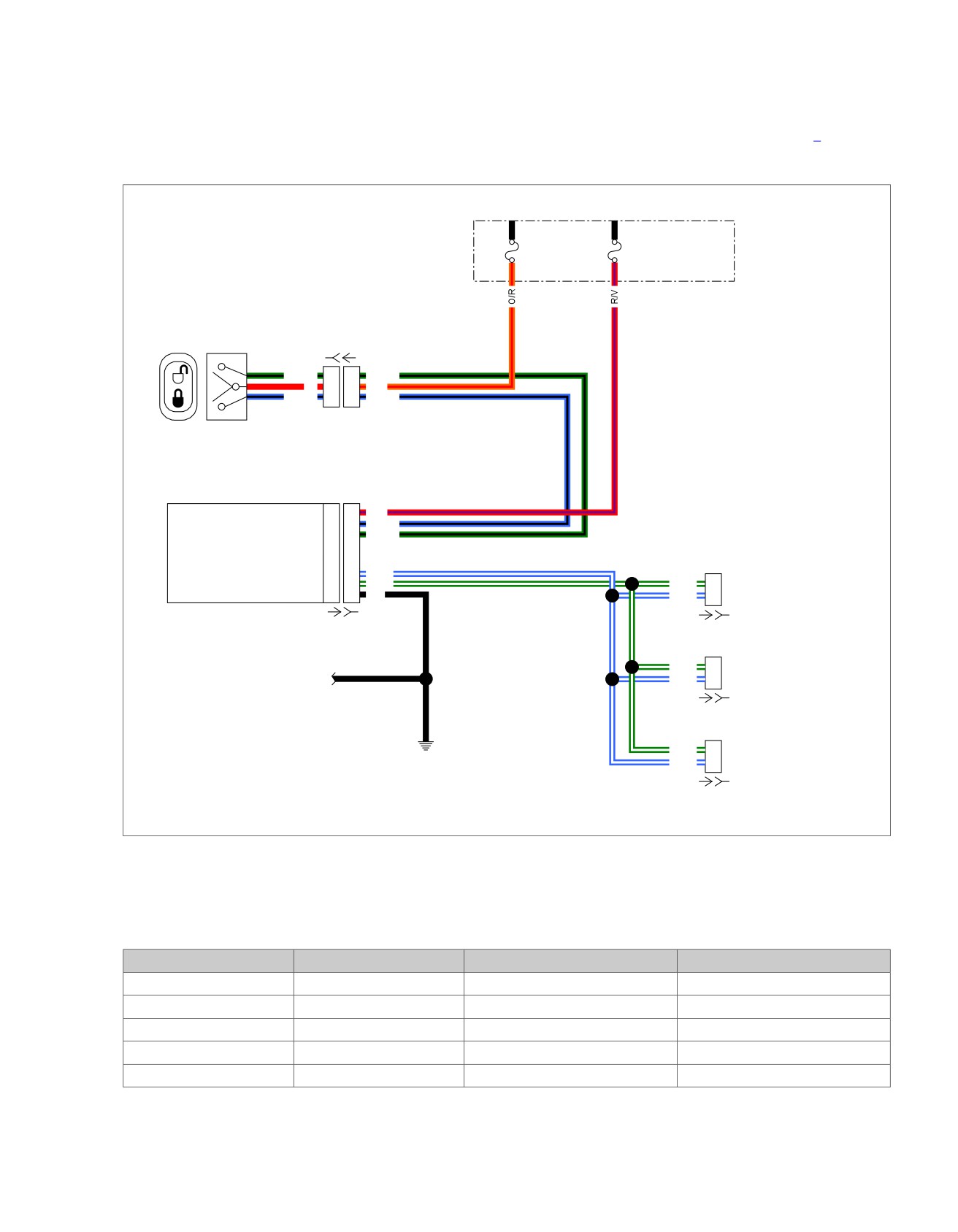
[212B] [212A]
GN/BK
1
1
GN/BK
R
2
2
O/R
BE/BK
3
3
BE/BK
Power Locks module
Battery power
1
1
R/V
Lock input
2
2
BE/BK
Unlock input
3
3
GN/BK
Lock signal
6
6
BE/W
Right Saddlebag Lock
Unlock signal
7
7
GN/W
GN/W
1
Power ground
8
8
BK
BE/W
2
[213RB]
[231A] [231B]
[213RA]
Left Saddlebag Lock
GN/W
1
Neutral Switch,
BE/W
2
[213LB]
Horn
[213LA]
GND
Tour-Pak Lock
GN/W
1
1A
BE/W
2
[213TB]
[213TA]
Figure 8-65. Power Locks Circuit
Table 8-14. Power Locks Circuit
NUMBER
DESCRIPTION
TYPE
LOCATION
[212]
Lock/Unlock Switch
3-place amp (T
yco)
In fairing cap
[213R]
Saddlebag Lock
2-place Deutsch
Behind RH saddlebag
[213L]
Saddlebag Lock
2-place Deutsch
Behind LH saddlebag
[213T]
T
our-Pak Lock
2-place Deutsch
Inside Tour-Pak liner
[231]
Power Locks Module
8-place
Inside outer fairing
2008 FLHTCUSE3 Service: Electrical 8-47
POWER LOCK MODULE
POWER LOCK FOB
See Figure 8-66. The lock module is located inside the outer
General
fairing and attached to the right fairing bracket.
See Figure 8-67. The fob remotely operates the power locks
Removal
in the saddlebags and Tour-Pak. The key on the fob may be
used to manually lock/unlock the ignition switch, saddlebags,
1. Remove the MAXIFUSE.
and Tour-Pak on the vehicle.
2. Remove outer fairing. See FAIRING CAP in Touring Ser-
Entering Program Mode
vice Manual.
NOTE
3. Disconnect harness connector from module (1).
To program a fob, it is necessary to put the receiver on the
4. Remove fastener (2). Remove module.
bike into program mode.
5. If necessary, remove fastener (3) and remove bracket (4).
1. Turn ignition knob to IGNITION or ACCESSORY.
Installation
NOTES
•
Verify that both saddlebags and the tour-pak power locks
1. If removed, install bracket (4) and tighten fastener (3) to
are functioning correctly when using the saddlebag/Tour-
30-50 in-lbs (3.4-5.6 Nm)
Pak lock switch.
2. Install module and tighten fastener (2) to 20-40 in-lbs (2.3-
•
Leave the Tour-Pak lid open during programming to see
4.5 Nm).
the Tour-Pak power lock hook move during lock and unlock
3. Install connector to module (1).
events.
4. Install outer fairing and connect MAXIFUSE.
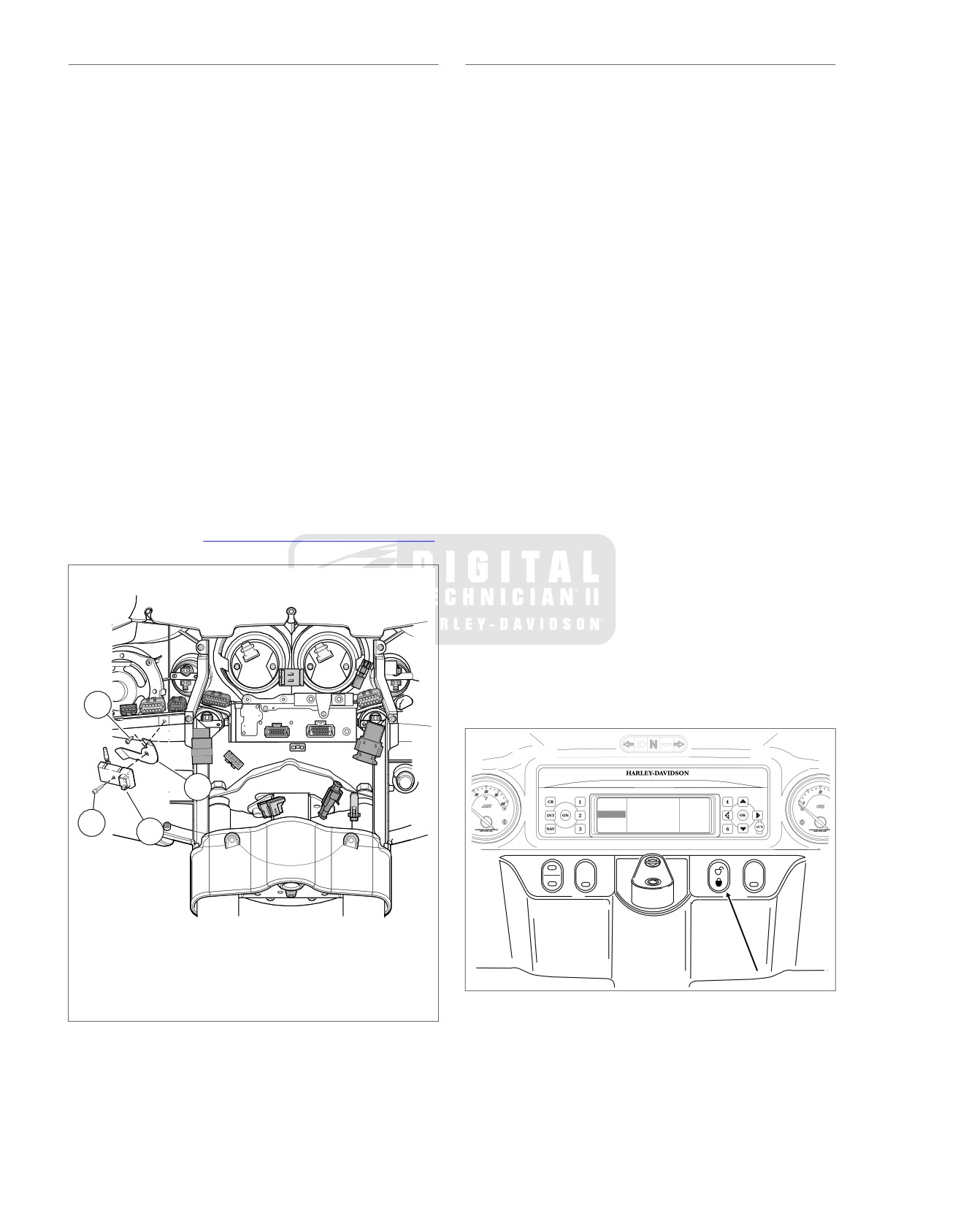
2. See Figure 8-69. Press UNLOCK on the saddlebag/Tour-
Pak lock switch to set locks to the unlocked position. Wait
NOTE
5 seconds.
If the power lock module is replaced, it must be programmed
to the fobs.
3. Press LOCK once on the saddlebag/Tour-Pak lock switch.
5. New power lock module must be programmed to operate
4. Press UNLOCK on the saddlebag/Tour-Pak lock switch 3
with the fobs. See 8.18 POWER LOCKS, Power Lock Fob.
times in a row.
5. Press LOCK on the saddlebag/Tour-Pak lock switch 3
ed01637
times in a row.
6. Press
and hold
UNLOCK for 5 seconds. After 5 seconds,
the actuators will cycle the locks to locked then back to
unlocked. The receiver is now beginning its program cycle.
7. Wait 11 more seconds. The actuators will once again cycle
to lock then back to unlock. The receiver is now in program
mode.
3
ed01638
4
88.7
FM 1
101.1
91.3
91.3 MHz
90.7
2
95.5
CB
INT
12:27
SCAN
More
1
CRUISE
SPKR
ACC
SPOT
1. Power lock module
2. Fastener
3. Module bracket
Figure 8-67. Saddlebag/Tour-Pak Lock Switch
4. Fastener
Figure 8-66. Power Lock Module
Program Mode
NOTE
Pressing lock or unlock on the saddlebag/Tour-Pak lock switch
during program mode will cause program mode to end.
8-48 2008 FLHTCUSE3 Service: Electrical