Harley Davidson 2004 Touring Models. Service Manual - page 45
HOME
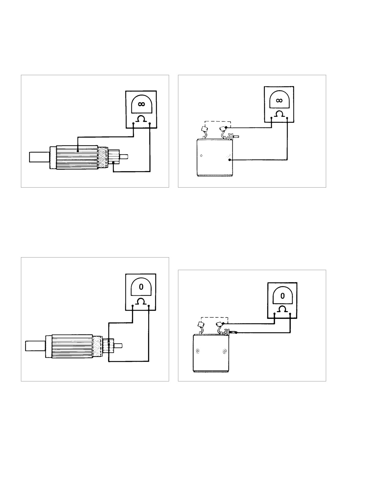
11. See Figure 5-12. Check for a GROUNDED ARMATURE
13. See Figure 5-14. Check for GROUNDED FIELD WIND-
with an ohmmeter or continuity tester. Touch one probe
ING with an ohmmeter or continuity tester. Touch one
to any commutator segment, and the other probe to the
probe to the frame, and the other probe to each of the
armature core. There should be no continuity (infinite
brushes attached to the field winding. There should be
ohms). If there is any continuity the armature is
no continuity (infinite ohms). If there is any continuity at
grounded and should be replaced.
either brush, the field winding(s) are grounded and the
field frame should be replaced.
Figure 5-12. Grounded Armature Test
Figure 5-14. Grounded Field Test
12. See Figure 5-13. Check for OPEN ARMATURE with an
14. See Figure 5-15. Check for OPEN FIELD WINDING with
ohmmeter or continuity tester. Check for continuity
an ohmmeter or continuity tester. Touch one probe to the
between all commutator segments. There should be
field wire, and the other probe to each of the brushes
continuity (0 ohms) at all test points. No continuity at any
attached to the field coils. There should be continuity. If
test point indicates armature is open and should be
there is no continuity at either brush, the field winding(s)
replaced.
are open and the field frame should be replaced.
Figure 5-13. Armature Open Test
Figure 5-15. Open Field Test
5-10
2004 Touring: Starter
HOME
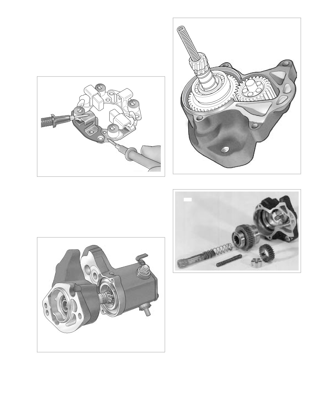
15. See Figure 5-16. Test BRUSH HOLDER INSULATION
with an ohmmeter or continuity tester. Touch one probe
f1540a5x
to holder plate and the other probe to each of the posi-
tive (insulated) brush holders. There should be no conti-
nuity (infinite ohms). If there is continuity at either brush
holder, the brush holder assembly should be replaced.
Touch one probe to the non-insulated brush holders and
the other probe to the holder plate. If you measure any
resistance, the brush holder must be replaced.
f1541x5x
Figure 5-18. Drive Housing Assembly
Figure 5-16. Brush Holder Insulation Test
16. Check armature bearings (10) and replace if necessary.
3506
See Figure 5-4.
NOTE
Spring (21) and ball (22) are loose in shaft gear end. See
Figure 5-4.
Figure 5-19. Clutch Assembly
17. See Figures 5-4, 5-17 and 5-18. Remove the two drive
housing mounting screws
(11) and washers
(12).
Remove drive housing (13) from solenoid housing (14).
18. See Figures 5-4 and 5-19. Remove drive (15), idler gear
(16) and idler gear bearing (17) from drive housing (13).
O-ring (18) is in groove in drive housing.
19. Remove spring (19) and shaft (20).
f1557x5x
Figure 5-17. Remove Drive Housing
2004 Touring: Starter
5-11
HOME
5.
Lubricate armature bearings (10) with high temperature
ASSEMBLY
grease such as LUBRIPLATE 110. Install armature (9)
and field coil (3) to solenoid housing (14).
1. See Figure 5-4. Replace O-rings (18, 23).
6.
Replace brush springs (6), if necessary. Install brushes
(7) and brush holder (8).
CAUTION
7.
Install end cap (4) with screws (5).
Do not use solvents to clean drive assembly/over-run-
8.
Install thru-bolts (2).
ning clutch (15). It is lubricated and sealed. If you use a
solvent to clean it, the lubricant will be washed out and
9.
Connect field wire (1) to solenoid terminal. Tighten sole-
the clutch will fail.
noid terminal nut to 70-90 in-lbs (7.9-10.2 Nm).
2. Clean, inspect and lubricate drive assembly compo-
nents. Lubricate parts with high temperature grease
such as LUBRIPLATE 110.
3. When installing drive assembly components, open end
of idler bearing cage (17) faces toward solenoid.
4. When installing drive housing (13) to solenoid housing
(14) use new O-ring (18). Be sure to install return spring
(21) and ball (22).
5-12
2004 Touring: Starter
HOME
STARTER SOLENOID
5.5
2.
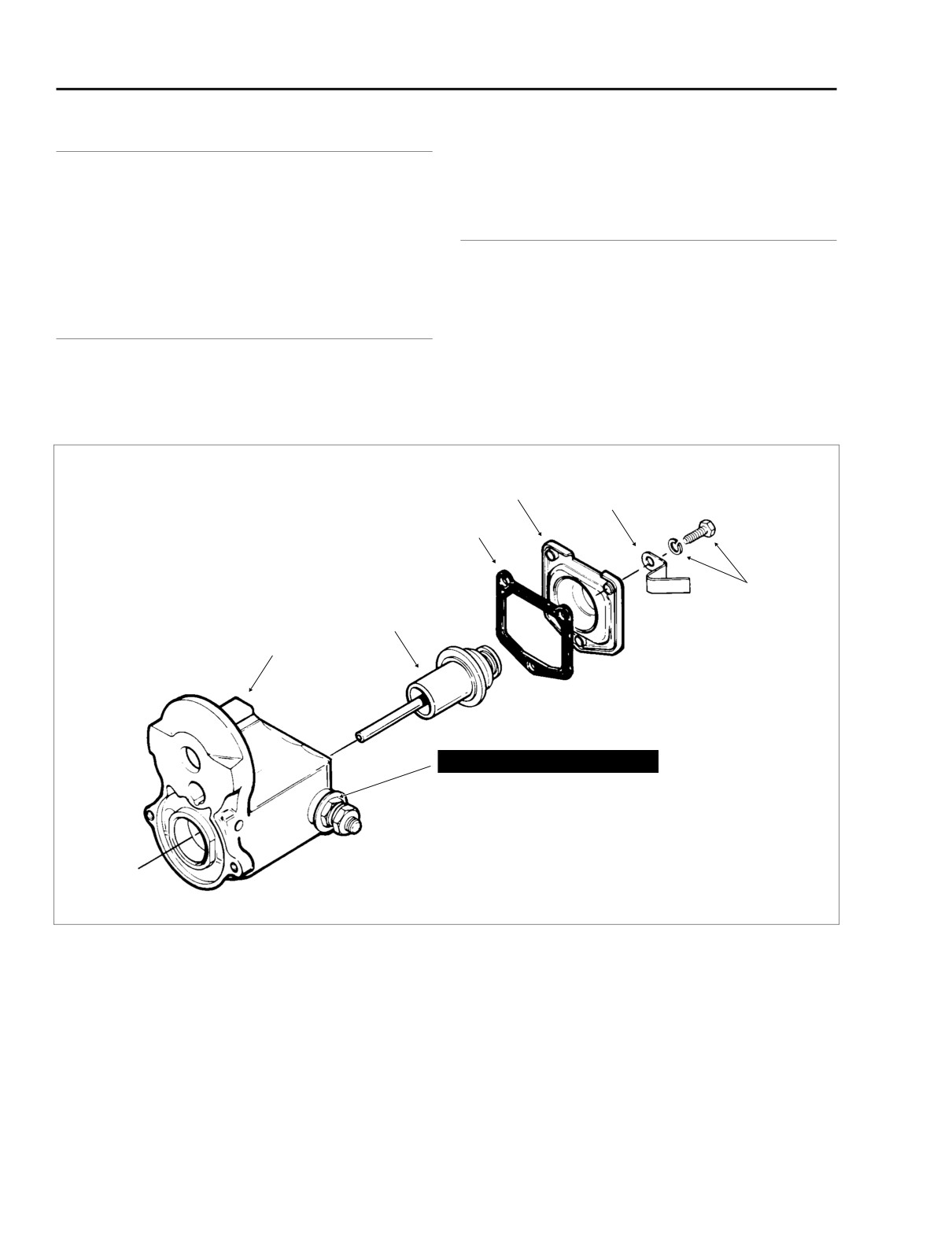
Remove cover and gasket. Discard gasket.
GENERAL
3.
Plunger can now be removed from solenoid housing.
The starter solenoid is a switch designed to open and close
the starting circuit electromagnetically. The switch consists of
contacts and a winding around a hollow cylinder containing a
movable plunger. When the winding is energized by the bat-
ASSEMBLY
tery, the magnetism produced pulls the plunger into the coil.
The plunger moves against two main switch contacts, closing
the circuit.
1.
Replace wire connection hardware as necessary.
2.
Apply a light coat of Lubriplate® 110 to plunger shaft.
DISASSEMBLY
Install plunger in solenoid housing.
1. See Figure 5-20. Remove screws and washers. Clip
3.
Install new gasket. Place cover in position and install
comes off with screw.
screws, washers and clip.
Cover
Clip
Gasket
Screw and
Washer
Plunger
Solenoid
Housing
CAUTION
Do not tighten the inside nut without
removing other items shown. Movement
will cause damage to the contact.
f1079axx
Figure 5-20. Starter Solenoid
5-13
2004 Touring: Starter
HOME
STARTER JACKSHAFT
5.6
REMOVAL/DISASSEMBLY
1.
Remove seat. See Section 2.24 SEAT, REMOVAL.
7945
1WARNING
To protect against shock and accidental start-up of vehi-
cle, disconnect the negative battery cable before pro-
ceeding. Inadequate safety precautions could result in
death or serious injury.
2.
Unthread bolt and remove battery negative cable (black)
from battery negative (-) terminal.
3.
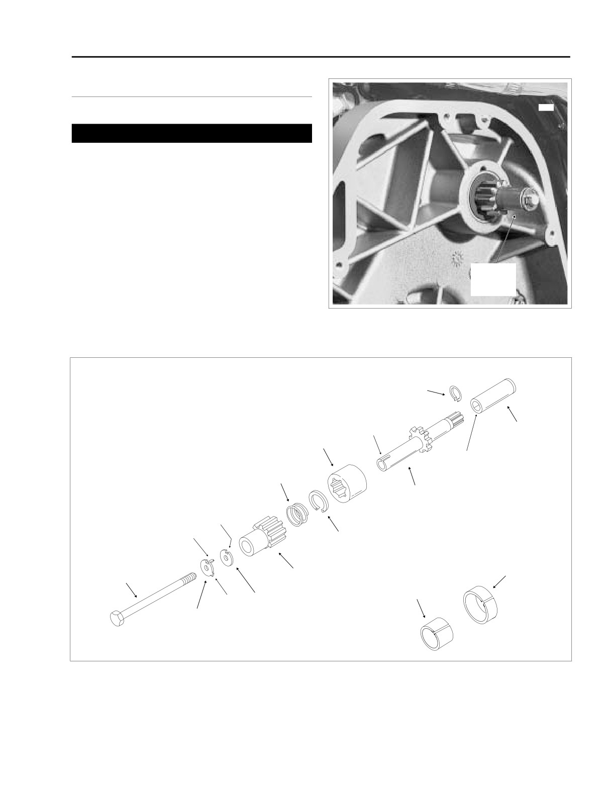
See Figure 5-21. Remove the primary chaincase cover.
Remove the clutch assembly, primary chain and com-
pensating sprocket components as a single assembly.
See Section 6.5 PRIMARY CHAINCASE, REMOVAL,
steps 3-15.
Starter
Jackshaft
NOTE
Assembly
If only the jackshaft bolt, thrust washer, lockplate, pinion gear
and/or spring require servicing, then the primary chain and
Figure 5-21. Primary Chaincase
clutch assembly may be left in place.
Retaining
Ring
f1211c5x
Keyway
Output
Coupling
Shaft
Coupling
Counterbore
Spring
Jackshaft
Slot
Key
Retaining
Ring
Primary Chaincase
Jackshaft
Bushing
Pinion
Bolt
Gear
Primary
Cover Bushing
Tab
Thrust
Washer
Lockplate
Figure 5-22. Starter Jackshaft Assembly
2004 Touring: Starter
5-14
HOME
4. Bend tab on lockplate away from head of jackshaft bolt.
3. Install oil filler plug/dipstick at top of transmission case.
See Figure 5-22.
4. Install slot of exhaust support bracket onto stud of
5. Holding pinion gear to prevent rotation, remove the jack-
bracket tab aligning other holes with those in starter
shaft bolt with lockplate and thrust washer.
flange. Start Keps nut on stud.
6. Carefully pull jackshaft assembly from the primary chain-
5. Engaging hole in exhaust support bracket, install starter
case bore.
front mounting screw with lockwasher. Install rear
mounting screw with lockwasher (and battery negative
7. Remove the pinion gear from the jackshaft.
cable ring terminal) in the same manner.
8. Remove the coupling from the jackshaft. Remove the
6. Alternately tighten starter front and rear mounting
spring from the coupling.
screws to 13-20 ft-lbs (18-27 Nm). Tighten Keps nut on
stud of bracket tab.
CAUTION
7. Install battery positive and main power cable ring termi-
Do not force the output shaft coupling through the oil
nals onto starter post. Install flange nut and tighten to
seal in the primary chaincase or the resulting damage
70-90 in-lbs (7.9-10.2 Nm). Pull down rubber boot over
will require seal replacement.
terminal connections on starter post.
8. Snap solenoid connector to terminal at top of starter
9. From right side of motorcycle, remove starter front
housing.
mounting screw with lockwasher. Remove rear mounting
screw with lockwasher (and battery negative cable ring
NOTE
terminal). Remove Keps nut from stud of bracket tab and
If removed, install allen screw to fasten decorative chrome
remove exhaust support bracket.
cover to starter.
10. Pull back rubber boot and remove flange nut from starter
post. Remove main power and battery positive cable
9.
Inspect the retaining ring within the coupling for damage
ring terminals from starter post.
or distortion. Replace as necessary.
11. Depress external latch and pull solenoid connector from
10.
Insert narrow end of jackshaft into shallow side of cou-
top of starter housing.
pling until gear face contacts installed retaining ring.
(Look at position of retaining ring within coupling to
12. Locate oil filler plug/dipstick at top of transmission case.
determine shallow side.)
To remove the oil filler plug, pull steadily while moving
plug back and forth.
11.
Slide spring over narrow end of jackshaft until it contacts
retaining ring.
13. Remove the starter from the right side of the motorcycle,
carefully sliding it through the space between the
12.
Slide pinion gear over narrow end of jackshaft until it
exhaust pipe and side cover.
contacts spring.
NOTE
13.
Slide lockplate and new thrust washer onto jackshaft
bolt, if removed. Insert bolt into jackshaft bore.
If necessary, remove allen screw and decorative chrome
cover to facilitate starter removal.
14.
Gently insert jackshaft assembly into primary chaincase
so that splined end of shaft engages coupling on starter
14. Remove the coupling from the starter motor output shaft.
output shaft.
15.
Insert key on lockplate through slot in thrust washer and
into keyway on jackshaft. Thread the jackshaft bolt into
ASSEMBLY/INSTALLATION
the starter shaft making sure that the lockplate key
remains in the keyway.
NOTE
16.
Holding pinion gear to prevent rotation, tighten jackshaft
bolt to 60-80 in-lbs (6.8-9.0 Nm). Bend tab on lockplate
To replace the jackshaft bushings and/or seals in the primary
against flat of bolt head to secure.
chaincase or primary chaincase cover, see Section 6.5 PRI-
MARY CHAINCASE, DISASSEMBLY.
17.
Install the clutch, primary chain, and compensating
sprocket components. Install the primary chaincase
1. Inspect the retaining ring within the output shaft coupling
cover. See Section
6.5 PRIMARY CHAINCASE,
for damage or distortion. Replace as necessary. With the
INSTALLATION, steps 9-31.
counterbore on the outboard side, install the coupling on
the starter motor output shaft, if removed.
18.
Insert bolt through battery negative cable (black) into
threaded hole of battery negative (-) terminal. Tighten
2. From right side of motorcycle, tilt starter and work into its
bolt to 60-96 in-lbs (6.8-10.9 Nm).
installed position. Starter output shaft coupling must
remain on shaft and mate to starter jackshaft.
19.
Install seat. See Section 2.24 SEAT, INSTALLATION.
2004 Touring: Starter
5-15
HOME
NOTES
5-16
2004 Touring: Starter
HOME
SPECIFICATIONS
6.1
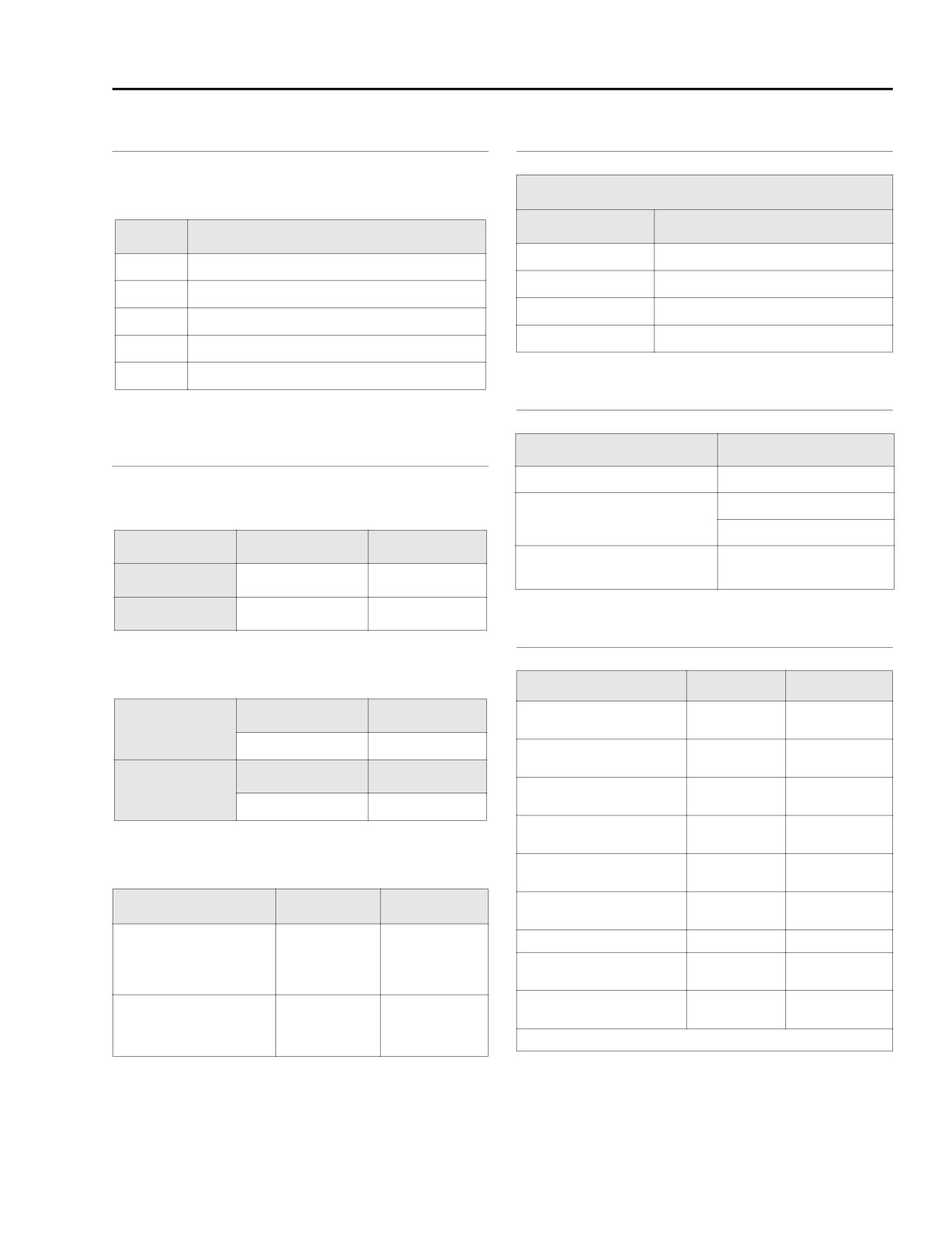
OVERALL GEAR RATIOS
SPROCKETS
Overall gear ratios indicate the number of engine revolutions
required to drive the rear wheel one revolution.
Number of Teeth
Sprocket
All Models
Gear
All Models
Engine
25
1
10.11
Clutch
36
2
6.96
Transmission
32
3
4.95
Rear wheel
70
4
3.86
5
3.15
CLUTCH
CHAINS AND BELTS
Clutch
Description
Type
Wet-multiple disc
Primary Chain Adjustments
1/16-1/8 in.
Clutch lever free play
1.6-3.2 mm
Free Play
Inches
Millimeters
loosen 1/2-1 turn after
Clutch screw adjustment
lightly seating
COLD Engine
5/8-7/8 inch
15.9-22.2 mm
HOT Engine
3/8-5/8 inch
9.5-15.9 mm
TORQUE VALUES
Primary Chaincase Lubricant
Item
ft/in-lbs
Nm
Primary chain tensioner
Ounces
Milliliters
21-29 ft-lbs
29-39 Nm
shoe nut
Amount
32
946
Tensioner shoe adjuster
12-14 ft-lbs
16-19 Nm
plate screws
Quart
Gallon
Primary chain inspection
84-108 in-lbs
10-12 Nm
Part Number
cover screws
99887-84
99886-84
Clutch adjuster screw
72-120 in-lbs
8-14 Nm
locknut
Rear Belt Adjustment
Clutch inspection cover
84-108 in-lbs
10-12 Nm
screws
Deflection
Inches
Millimeters
Clutch diaphragm spring
90-110 in-lbs
10-12 Nm
retainer to clutch hub bolts
On Jiffy Stand Without
Rear axle cone nut
95-105 ft-lbs
129-142 Nm
Rider or Luggage
1/4 - 5/16
6.4
- 7.9
Rear swingarm pivot
10 psi (69 kPa)
at 10 lbs force
at 4.5 kg force
40-45 ft-lbs
54-61 Nm
shaft locknut
in Rear Shocks
Rear swingarm bracket
Motorcycle Upright
34-42 ft-lbs
46-57 Nm
3/16 - 1/4
4.8
- 6.4
bolts
With Rear Wheel
at 10 lbs force
at 4.5 kg force
Continued ...
in the Air
2004 Touring: Drive
6-1

HOME
TORQUE VALUES (CONT.’D)
Item
ft/in-lbs
Nm
Shock bottom
35-40 ft-lbs
47-54 Nm
mounting bolt
Exhaust pipe TORCA
45-60 ft-lbs
61-81 Nm
clamps
Heat shield worm drive
20-40 in-lbs
2.3-4.5 Nm
clamp screws
Transmission mainshaft
60 ft-lbs, then
81 Nm, then
sprocket nut
35° to 45°
35° to 45°
Mainshaft sprocket nut
lockplate socket head
90-110 in-lbs
10-12 Nm
screws
Rear wheel sprocket bolts
55-65 ft-lbs
75-88 Nm
Primary chaincase to
crankcase and transmis-
18-21 ft-lbs
24-28 Nm
sion
Front and rear starter
13-20 ft-lbs
18-27 Nm
mounting screws
Starter jackshaft bolt
60-80 in-lbs
6.8-9.0 Nm
Engine compensating
150-165 ft-lbs
203-224 Nm
sprocket nut
Clutch hub mainshaft nut
70-80 ft-lbs
95-108 Nm
Primary chaincase cover
84-108 in-lbs
9-12 Nm
allen head socket screws
Primary chaincase drain
36-60 in-lbs
4.1-6.8 Nm
plug
Passenger footboard
15-18 ft-lbs
20-24 Nm
socket screws
1/4”
90-110 in-lbs
10.2-12.4 Nm
Shifter lever
socket screws
5/16”
18-22 ft-lbs
24-30 Nm
6-2
2004 Touring: Drive
HOME
PRIMARY CHAIN AND SPROCKETS
6.2
PRIMARY CHAIN ADJUSTMENT
f1840x6x
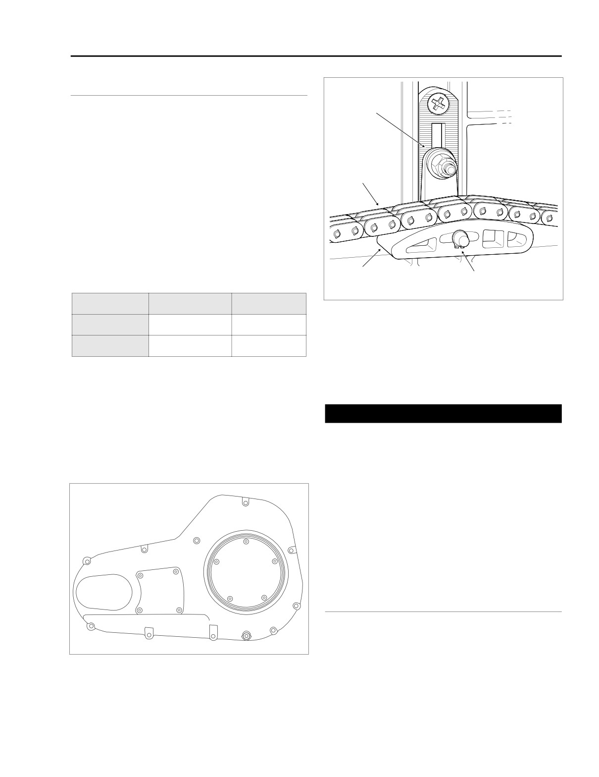
Top Center Nut
At the 1000 mile (1600 km) service interval, and at every
5000 mile (8000 km) service interval thereafter, inspect the
primary chain tension. Proceed as follows:
1. See Figure 6-1. Using a T27 TORX drive head, remove
four screws to free the primary chain inspection cover
Primary
from the primary chaincase cover.
Chain
2. Check the primary chain tension. Push on the upper
strand to verify that it has free up and down movement
midway between the engine compensating sprocket
(front) and the clutch sprocket (rear).
3. Measure the free play to be sure that it falls within the
ranges specified for a hot or cold engine:
Adjuster Shoe
Retaining
Table 6-1. Primary Chain Adjustment
Narrow End Forward
Ring
(Free Play)
Inches
Millimeters
Figure 6-2. Chain Tensioner Assembly
COLD ENGINE
5/8-7/8 inch
15.9-22.2 mm
NOTE
HOT ENGINE
3/8-5/8 inch
9.5-15.9 mm
As chains stretch and wear, they run tighter at one spot than
another. Always adjust the free play at the tightest spot in the
4. If the chain is too tight or too loose, then adjust as fol-
chain. Replace the primary chain if it is worn to the point
lows:
where it cannot be properly adjusted.
a. Locate the chain tensioner assembly and loosen the
CAUTION
top center nut a maximum of two turns. See Figure
6-2.
Always keep the primary chain properly adjusted. Allow-
ing the chain to run too tight or too loose will result in
b. Raise or lower the chain tensioner assembly as
excessive chain and sprocket wear.
necessary to obtain the specified free play.
c. Tighten the top center nut of the chain tensioner
assembly to 21-29 ft-lbs (29-39 Nm).
f1210x6x
5. Align holes in new gasket with holes in the primary
chaincase cover. Using a T27 TORX drive head, install
four screws to secure primary chain inspection cover to
primary chaincase cover. Alternately tighten screws to
1
84-108 in-lbs (10-12 Nm) in a crosswise pattern. See
1
4
Clutch
3
Figure 6-1.
4
Inspection
Cover
Primary
Chain
Inspection
2
5
Cover
ADJUSTER SHOE REPLACEMENT
2
3
If the nylon adjuster shoe is worn or damaged, replace as fol-
lows:
1. Remove the primary chaincase cover. See Section 6.5
Figure 6-1. Primary Chaincase Cover
PRIMARY CHAINCASE, REMOVAL, steps 1-8.
2004 Touring: Drive
6-3
HOME
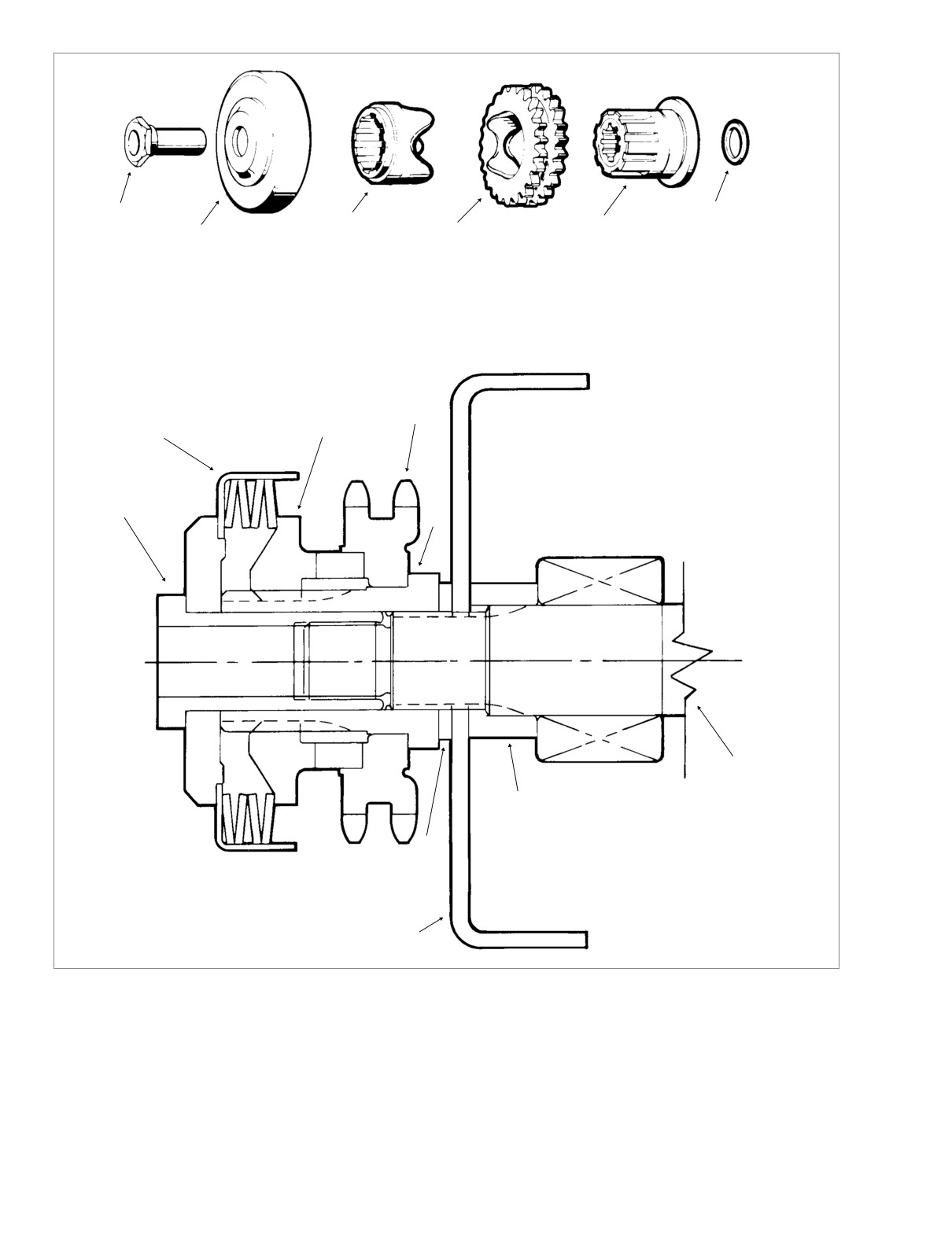
f1096dxd
6
1
3
5
4
2
1.
Sprocket Nut
6. Alternator Rotor Spacer-
7.
Alternator Rotor
2.
Sprocket Cover
Low Output Rotor Only
8.
Sprocket Shaft Spacer
3.
Sliding Cam
0.020 inch (0.508 mm)
9.
Engine Sprocket Shaft
4.
Compensating Sprocket
5.
Shaft Extension
EXPLODED VIEW
4
3
2
NOTE
Alternator stator, oil seal and left
crankcase not shown.
1
5
9
8
6
CROSS SECTIONAL VIEW
7
Figure 6-3. Engine Compensating Sprocket Components
2.
Loosen top center nut from captured bolt of chain ten-
3. Lower the chain tensioner assembly until the adjuster
sioner assembly. See Figure 6-2.
shoe just contacts the inner primary housing.
6-4
2004 Touring: Drive
HOME
1WARNING
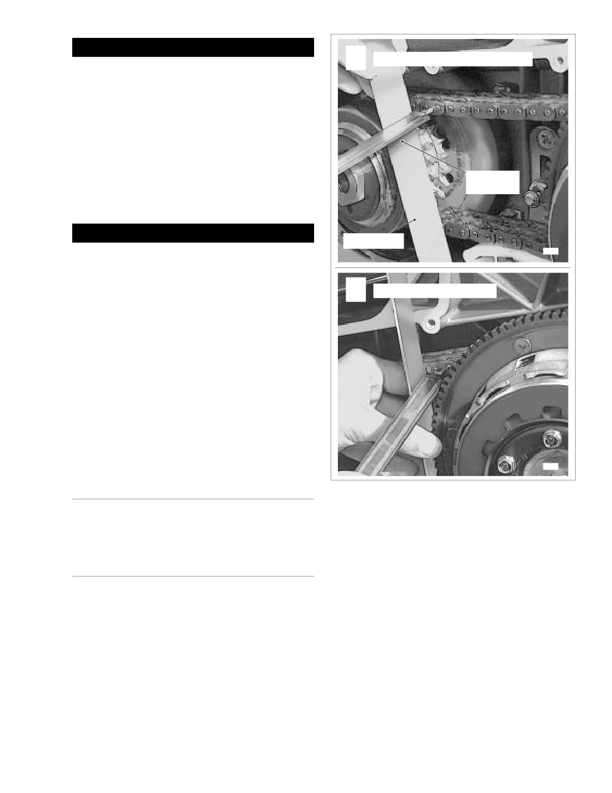
Measure at Compensating Sprocket
A
Always wear proper eye protection when removing re-
taining rings. Use the correct retaining ring pliers. Verify
that the tips of the pliers are not damaged or excessively
worn. Slippage may propel the ring with enough force to
cause eye injury.
4.
Remove retaining ring from nub and pull adjuster shoe
from chain tensioner. Discard adjuster shoe and retain-
ing ring.
5. Slide new adjuster shoe onto chain tensioner. Be sure
Dial Vernier
Caliper
that the narrow end of the shoe is at the front, the wider
end at the rear.
1WARNING
Straightedge
Always wear proper eye protection when installing re-
7949
taining rings. Use the correct retaining ring pliers. Verify
that the tips of the pliers are not damaged or excessively
worn. Slippage may propel the ring with enough force to
Measure at Clutch Sprocket
B
cause eye injury.
6.
To lock position of adjuster shoe, install new retaining
ring onto nub of chain tensioner. Verify that retaining ring
is fully seated in the groove.
7.
Raise or lower the chain tensioner assembly as neces-
sary to obtain the specified free play. See PRIMARY
CHAIN ADJUSTMENT, steps 2-4.
8.
Tighten the top center nut of the chain tensioner assem-
bly to 21-29 ft-lbs (29-39 Nm).
9. Install the primary chaincase cover. See Section 6.5
PRIMARY CHAINCASE, INSTALLATION, steps 20-31.
7947
DISASSEMBLY
Figure 6-4. Check Sprocket Alignment
See Section 6.5 PRIMARY CHAINCASE, REMOVAL, steps
Sprocket Alignment (Figure 6-3, 6-4)
1-16.
The engine compensating sprocket is aligned with the clutch
sprocket by a spacer installed between the alternator rotor
CLEANING AND INSPECTION
and shaft extension (low output rotor only). Reinstall the
same thickness spacer removed or determine the correct
1. Periodically inspect the primary chain for cracked, bro-
spacer size as follows:
ken or badly worn links. Replace as necessary.
1. With the primary chaincase cover removed, verify that
2. Inspect compensating sprocket components for damage
the primary chain tension is properly adjusted. See PRI-
or wear. Replace parts as necessary.
MARY CHAIN ADJUSTMENT in this section.
3. Inspect clutch sprocket for damage or wear. If broken or
2. At both the engine compensating sprocket and clutch
damaged teeth are found, the clutch shell and sprocket
sprocket sides, push the primary chain inward as far as it
assembly must be replaced.
will go.
2004 Touring: Drive
6-5

HOME
3.
Place a straightedge vertically across the flanges (cover
ASSEMBLY
gasket surface) near the engine compensating sprocket.
4.
Using a dial vernier caliper, measure the distance from
See Section
6.5 PRIMARY CHAINCASE, INSTALLATION,
the straightedge to the chain link sideplate. Measure as
steps 8-31.
close to the engine compensating sprocket as possible
and record the measurement. See A of Figure 6-4.
5.
Repeat the measurement on the clutch sprocket side.
See B of Figure 6-4.
For proper primary chain alignment, the difference
between the two measurements must not exceed 0.030
inch (0.76 mm). If the measurement is not within specifi-
cation, install the appropriate variable thickness spacer
on the engine sprocket shaft between the alternator rotor
and shaft extension. See the adjacent table for the vari-
ous spacer thicknesses.
Table 6-2. Alternator Rotor Spacers
Inches
Millimeters
Part Number
0.010
0.25
35850-84
0.020
0.51
35851-84
0.030
0.76
35852-84
0.060
1.52
24032-70
0.090
2.29
24033-70
0.120
3.05
24034-70
0.150
3.81
24035-70
0.180
4.57
24036-70
0.210
5.33
24037-70
6-6
2004 Touring: Drive
HOME
CLUTCH
6.3
ADJUSTMENT
f1440x6x
Jam
Nut
CAUTION
Rubber
Perform the clutch adjustment with the motorcycle at
Boot
room temperature. The clearance at the adjuster screw
will increase as the power train temperature increases. If
Cable
adjuster screw is adjusted while the powertrain is hot,
End
clearance at push rod bearing could be insufficient with
power train cold and clutch slippage could occur.
Cable
Adjuster
Adjust the clutch at the 1000 mile (1600 km) service interval,
and at every 5000 mile (8000 km) service interval thereafter.
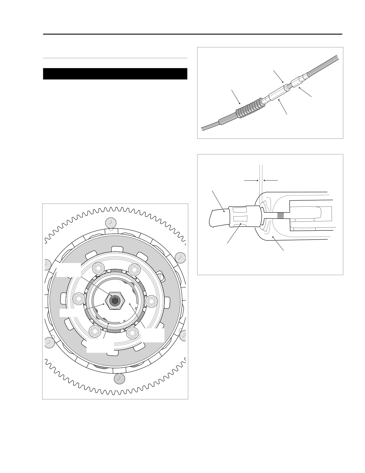
Figure 6-6. Clutch Cable Adjuster Mechanism
NOTE
Also perform adjustment procedure whenever any clutch
components are replaced. Then repeat adjustment after first
Adjust for 1/16-1/8 inch
500 miles (800 km) of use.
(1.6-3.2 mm) gap
between ferrule
Clutch
and bracket
1. Stand motorcycle upright and level.
Cable
Ferrule
Clutch Lever
Bracket
Adjuster
f1421x6x
Screw
Figure 6-7. Adjust Clutch Free Play
2.
Using a T27 TORX drive head, remove five screws (with
captive washers) to free clutch inspection cover from pri-
Locknut
mary chaincase cover.
3.
See Figure 6-6. Slide rubber boot off cable adjuster.
Holding cable adjuster with 1/2 inch wrench, loosen jam
Release
nut using a 9/16 inch wrench. Back jam nut away from
Plate
cable adjuster. Move adjuster toward jam nut to intro-
Retaining
Ring
duce a large amount of free play at hand lever.
4.
See Figure 6-5. Loosen locknut on clutch adjuster screw.
To take up all free play in push rods, turn screw inward
(clockwise) until lightly seated.
5.
Back out adjuster screw 1/2 to 1 turn. While holding
adjuster screw with an allen wrench, tighten locknut to
f1509b6x
72-120 in-lbs (8-14 Nm).
6.
Squeeze clutch lever to maximum limit three times to set
Figure 6-5. Clutch Adjustment
ball and ramp release mechanism.
2004 Touring: Drive
6-7
HOME
7. Turn cable adjuster away from jam nut until slack is elim-
inated at hand lever. Pull clutch cable ferrule away from
f1523x6x
Damper
Clutch
clutch lever bracket to check free play. Turn cable
Spring
Hub
adjuster as necessary to obtain 1/16 to 1/8 inch (1.6-3.2
Clutch
mm) free play between end of cable ferrule and clutch
Shell
lever bracket, as shown in Figure 6-7.
Steel Plate
8.
Hold adjuster with 1/2 inch wrench. Using 9/16 inch
wrench, tighten jam nut against cable adjuster. Cover
cable adjuster mechanism with rubber boot.
9.
Remove quad ring from groove in primary chaincase
cover. Wipe all lubricant from the quad ring and inspect
for cuts, tears or signs of deterioration. Replace as nec-
essary.
10. Swab all lubricant from the quad ring groove. Install
quad ring in primary chaincase cover with the nubs con-
Damper
Narrow
tacting the ring groove walls.
Spring Seat
Friction Plate
NOTE
If lubricant is not thoroughly removed from both the quad ring
and groove, compression of the ring during installation of the
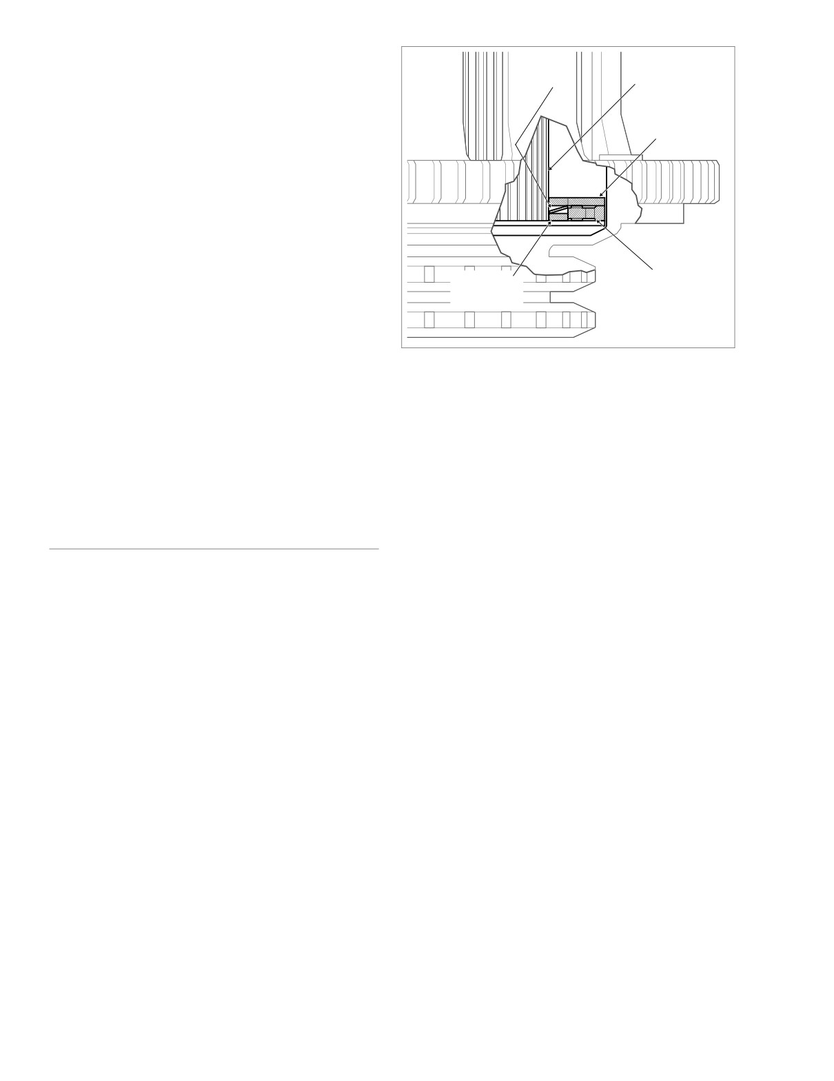
Figure 6-8. Clutch Pack Stack-Up (Cut-Away View)
clutch inspection cover can cause lubricant to be squeezed
to the outboard side of the ring groove, resulting in some
temporary weepage around the inspection cover.
4.
Remove friction plates, steel plates, damper spring and
damper spring seat from clutch hub.
11. Using a T27 TORX drive head, install five screws (with
captive washers) to secure clutch inspection cover to the
5.
See CLEANING AND INSPECTION in this section.
primary chaincase cover. Alternately tighten screws to
84-108 in-lbs (10-12 Nm) in the pattern shown in Figure
ASSEMBLY
6-1.
CLUTCH PACK ONLY
1.
Submerge and soak all friction and steel plates in PRI-
REMOVAL/INSTALLATION
MARY CHAINCASE LUBRICANT for at least five min-
utes.
To remove the clutch without disassembly, see Section 6.5
2.
Install the narrow friction plate on the clutch hub engag-
PRIMARY CHAINCASE, REMOVAL, steps 1-16.
ing tabs on plate with slots in clutch shell.
For installation instructions, see Section
6.5 PRIMARY
3.
Install damper spring seat on clutch hub so that it seats
CHAINCASE, INSTALLATION, steps 8-31.
inboard of narrow friction plate.
NOTE
4.
Install damper spring on clutch hub with the concave
side up (facing opposite damper spring seat). See Fig-
If only the clutch pack is to be disassembled, see PARTIAL
ure 6-8.
DISASSEMBLY below, a procedure that can be performed on
the motorcycle without removing the clutch shell or hub.
5.
Install a steel plate and then a friction plate on the clutch
hub. Install seven remaining sets in the same manner,
For complete disassembly of the clutch, which includes
alternating between steel plates and friction plates.
clutch pack disassembly and bearing replacement, see
6.
Install pressure plate on clutch hub aligning holes in
COMPLETE DISASSEMBLY.
plate with threaded bosses on hub.
7.
Seat diaphragm spring in recess of pressure plate with
PARTIAL DISASSEMBLY
the concave side down.
8.
Align holes in diaphragm spring retainer with threaded
CLUTCH PACK ONLY
bosses on clutch hub. Tabs on spring retainer contact
1. Remove the primary chaincase cover. See Section 6.5
flats on inboard side of bosses.
PRIMARY CHAINCASE, REMOVAL, steps 1-8.
9.
Install six bolts to secure diaphragm spring retainer to
2. Remove six bolts to release diaphragm spring retainer
clutch hub. Alternately tighten bolts to
90-110 in-lbs
from clutch hub. See Figure 6-9.
(10.2-12.4 Nm).
3. Remove diaphragm spring retainer, diaphragm spring
10.
Install the primary chaincase cover. See Section 6.5
and pressure plate from clutch hub.
PRIMARY CHAINCASE, INSTALLATION, steps 20-31.
6-8
2004 Touring: Drive
HOME
f1514x6x
5
6
4
2
3
7
8
1
9
10
11
17
16
14
18
15
19
12
23
20
13
21
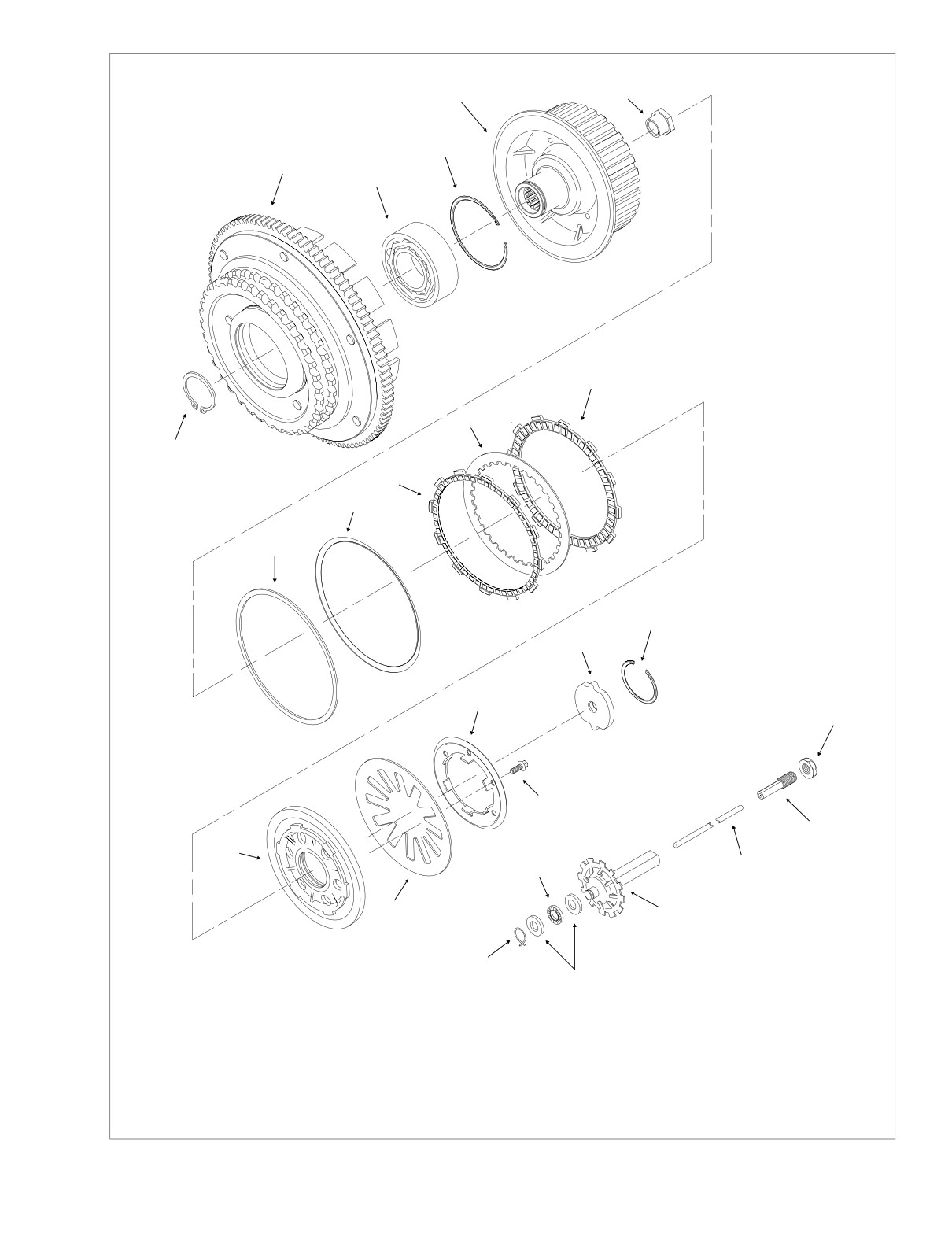
1. Retaining Ring
24
2. Clutch Shell
22
3. Bearing
10. Damper Spring
4. Retaining Ring
11. Damper Spring Seat
5. Clutch Hub
12. Pressure Plate
17. Retaining Ring
6. Mainshaft Nut
13. Diaphragm Spring
18. Locknut
7. Friction Plate (9)
14. Diaphragm Spring Retainer
19. Adjuster Screw
22. Thrust Washer (2)
8. Steel Plate (8)
15. Bolt (6)
20. Push Rod
23. Throw Out Bearing
9. Narrow Friction Plate
16. Release Plate
21. Oil Slinger
24. Retaining Ring
Figure 6-9. Clutch Assembly
2004 Touring: Drive
6-9
HOME
CLEANING AND INSPECTION
Remove retaining ring from clutch hub.
1.
Wash all parts in cleaning solvent, except for friction
plates and bearing, if removed. Blow dry with com-
pressed air.
2.
Check friction plates as follows:
● Wipe all lubricant from the friction plates. Measure
the thickness of each plate with a dial caliper or
micrometer. If the thickness of any plate is less than
0.143 inch (3.62 mm), discard the friction plates and
replace with an entirely new set.
● Look for worn or damaged fiber surface material
(both sides).
NOTE
Replace all nine friction plates with an entirely new set if any
individual plate shows evidence of wear or damage.
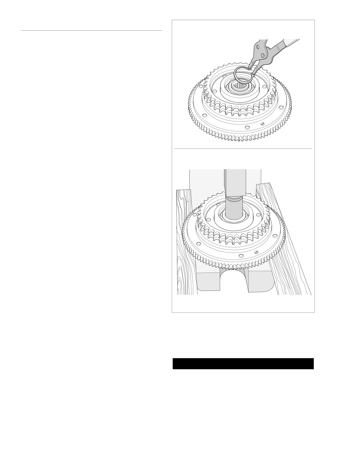
f1519x6x
3. Check steel plates as follows:
Press clutch hub from bearing.
● Discard any plate that is grooved or bluish in color.
Blue plates are likely warped or distorted.
● Check each plate for distortion. Lay the plate on a
precision flat surface. Insert a feeler gauge between
the plate and the flat surface in several places.
Replace any steel plate that is warped more than
0.006 inch (0.15 mm).
4. See Figure 6-9. Holding the clutch hub, rotate the clutch
shell to check bearing for smoothness. Replace the
bearing if it runs rough or binds.
5. Check the primary chain sprocket and the starter ring
gear on the clutch shell. Replace the clutch shell if either
sprocket or ring gear are badly worn or damaged.
6. Check the slots that mate with the clutch plates on both
the clutch shell and hub. Replace shell or hub if slots are
worn or damaged.
7. Check the diaphragm spring and diaphragm spring
retainer for cracks or bent tabs. Obtain a new diaphragm
spring or diaphragm spring retainer if either condition
f1522x6x
exists.
Figure 6-10. Remove Clutch Hub from Clutch Shell
COMPLETE DISASSEMBLY
4.
Remove friction plates, steel plates, damper spring and
CLUTCH PACK AND BEARING
damper spring seat from clutch hub.
1. Remove clutch assembly from the motorcycle. See Sec-
tion 6.5 PRIMARY CHAINCASE, REMOVAL, steps 1-16.
CAUTION
2. Remove six bolts to release diaphragm spring retainer
To avoid possible bearing damage, do not disassemble
from clutch hub. See Figure 6-9.
the clutch shell and hub assembly unless the bearing,
3. Remove diaphragm spring retainer, diaphragm spring
hub or shell require replacement. Replace the bearing if
and pressure plate from clutch hub.
disassembled.
6-10
2004 Touring: Drive
HOME
6.
Supporting clutch shell in same orientation, use arbor
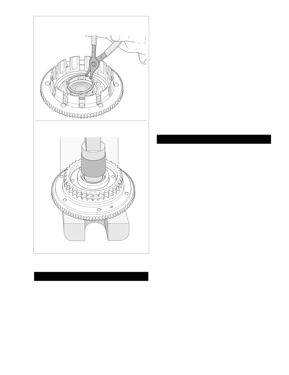
press and a suitable press plug to press hub from bear-
Remove retaining ring from clutch shell.
ing in clutch shell. See lower frame of Figure 6-10.
7.
Turn clutch shell over so that the sprocket side is down.
Remove retaining ring from groove in clutch shell bore.
See upper frame of Figure 6-11.
8.
Turn clutch shell over so that sprocket side is up. Using
arbor press and a suitable press plug, press on inner
race to remove bearing from clutch shell bore. See lower
frame of Figure 6-11.
9.
See CLEANING AND INSPECTION in this section.
ASSEMBLY
CLUTCH PACK AND BEARING
1.
Orient clutch shell in arbor press with sprocket side
f1521x6x
down. Be sure to support clutch shell bore on sprocket
side. Using a suitable press plug, press against outer
Press bearing from clutch shell.
race until bearing contacts shoulder in clutch shell bore.
1WARNING
Always wear proper eye protection when installing re-
taining rings. Use the correct retaining ring pliers. Verify
that the tips of the pliers are not damaged or excessively
worn. Slippage may propel the ring with enough force to
cause eye injury.
NOTE
Note that one side of the retaining ring is beveled. Always
install the ring with the beveled side opposite the bearing.
2.
Install retaining ring in groove of clutch shell bore, so
that the flat side of the ring is in towards the bearing, the
beveled side out.
3.
Center hub in bearing. Be sure that bearing inner race is
supported with sleeve on sprocket side. Press hub into
bearing until hub shoulder contacts bearing inner race.
4.
Turn assembly over so that the sprocket side is up.
Install retaining ring in groove of clutch hub.
f1520x6x
5.
Place clutch assembly on bench oriented with the
sprocket side down.
Figure 6-11. Remove Bearing from Clutch Shell
6.
Submerge and soak all friction and steel plates in PRI-
MARY CHAINCASE LUBRICANT for at least five min-
utes.
1WARNING
7.
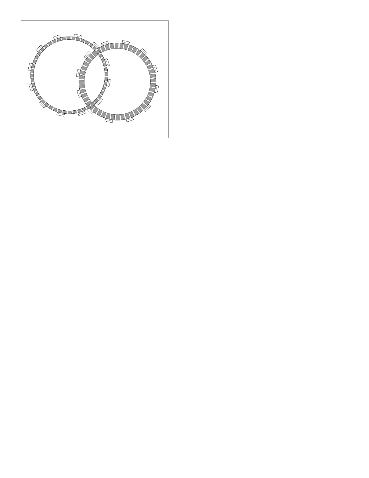
Install the narrow friction plate on the clutch hub engag-
Always wear proper eye protection when removing re-
ing tabs on plate with slots in clutch shell. See Figure 6-
taining rings. Use the correct retaining ring pliers. Verify
12.
that the tips of the pliers are not damaged or excessively
8.
Install damper spring seat on clutch hub so that it seats
worn. Slippage may propel the ring with enough force to
inboard of narrow friction plate.
cause eye injury.
9.
Install damper spring on clutch hub with the concave
5.
With the sprocket side up, remove retaining ring from
side up (facing opposite damper spring seat). See Fig-
clutch hub groove. See upper frame of Figure 6-10.
ure 6-8.
2004 Touring: Drive
6-11
HOME
12. Seat diaphragm spring in recess of pressure plate with
Narrow Plate
the concave side down.
13. Align holes in diaphragm spring retainer with threaded
bosses on clutch hub. Tabs on spring retainer contact
flats on inboard side of bosses.
14. Install six bolts to secure diaphragm spring retainer to
clutch hub. Alternately tighten bolts to
90-110 in-lbs
(10.2-12.4 Nm).
15. Install clutch assembly on motorcycle. See Section 6.5
PRIMARY CHAINCASE, INSTALLATION, steps 8-31.
Regular Plate
f1513x6x
Figure 6-12. Friction Plates
10. Install a steel plate and then a friction plate on the clutch
hub. Install seven remaining sets in the same manner,
alternating between steel plates and friction plates.
11. Install pressure plate on clutch hub aligning holes in
plate with threaded bosses on hub.
6-12
2004 Touring: Drive
HOME
SECONDARY DRIVE BELT AND SPROCKETS
6.4
ADJUSTMENT
Transmission
Rear Wheel
Sprocket
Sprocket
1.
Remove left side saddlebag. See Section 2.25 SAD-
DLEBAG, REMOVAL.
2.
Check deflection at the loosest spot in the belt with the
transmission in neutral and the motorcycle cold. Use
BELT TENSION GAUGE (HD-35381A), or install narrow
saddle (HD-35381-3) on existing gauge, and apply 10
lbs. (4.5 kg) of force at the midpoint of the bottom belt
10 lbs. (4.5 kg)
strand. See Figure 6-13. Belt deflection should be as fol-
of Force
lows:
See Table 6-3.
f1652x6x
Table 6-3. Belt Deflection
Orientation
Inches
Millimeters
Figure 6-13. Check and Adjust Belt Deflection
On Jiffy Stand
Without Rider or Luggage
1/4 - 5/16
6.4
- 7.9
b. Using a bungee cord, tie the muffler to the lower
10 psi (69 kPa) in Rear Shocks
saddlebag support rail.
Motorcycle Upright
3/16 - 1/4
4.8
- 6.4
With Rear Wheel in the Air
c. Loosen TORCA clamp between rear header pipe
and muffer.
If belt deflection is within specification, install left side
d. Remove two bolts (with lockwashers) to detach muf-
saddlebag. If adjustment is necessary, proceed to step
fler from the lower saddlebag support rail.
3.
e. Remove bungee cord to release muffler from lower
3.
Remove right side saddlebag. See Section 2.25 SAD-
saddlebag support rail.
DLEBAG, REMOVAL.
4.
Remove right side muffler as follows:
5.
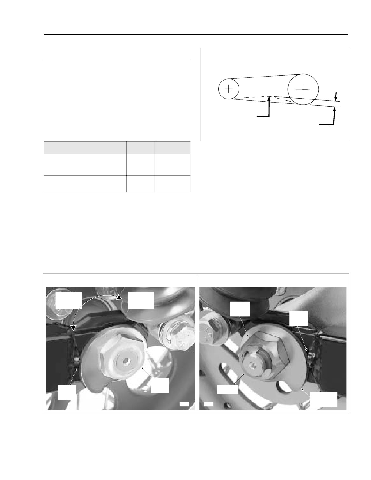
Standing on right side of motorcycle, remove E-clip from
a. Open worm drive clamps to remove heat shield
groove at end of axle. Loosen cone nut, and then snug
from rear header pipe in front of muffler.
to 15-20 ft-lbs (20-27 Nm). See Figure 6-14.
LEFT SIDE
RIGHT SIDE
Increase
Reduce
Belt
Belt
Deflection
Deflection
Cone
Nut
Weld
Nub
Weld
Weld
Nut
E-Clip
Nub
Adjuster
8398
8407
Cam
Figure 6-14. Move Rear Wheel Forward Until Adjuster Cams Just Contact Weld Nubs
2004 Touring: Drive
6-13