Harley Davidson 2004 Touring Models. Service Manual - page 40
HOME
7.
Rotate crankcase in the engine stand so that the stator
mount flange (sprocket shaft side) is facing upward.
1
Install service thrust washer on sprocket shaft with the
ink stamp facing outside (and the chamfer inboard). If
using OE part without markings, orient as required to
preserve existing wear pattern.
5
4
8.
To install new oil seal into bearing bore, obtain pilot,
Nice bearing, large flat washer and handle from
SPROCKET SHAFT TIMKEN BEARING CONE
INSTALLER (HD-97225-55B) and proceed as follows:
7
8
a. Verify that seal lip garter spring is in place on both
sides of seal.
b. Thread pilot onto sprocket shaft until contact is
made with shoulder.
c. With the lettering facing outside, slide oil seal over
pilot until it contacts bearing bore.
2
3
d. Slide SPROCKET SHAFT OIL SEAL INSTALLER
(HD-39361A) over pilot until it contacts oil seal. See
Figure 3-47.
9
6
f1585x3x
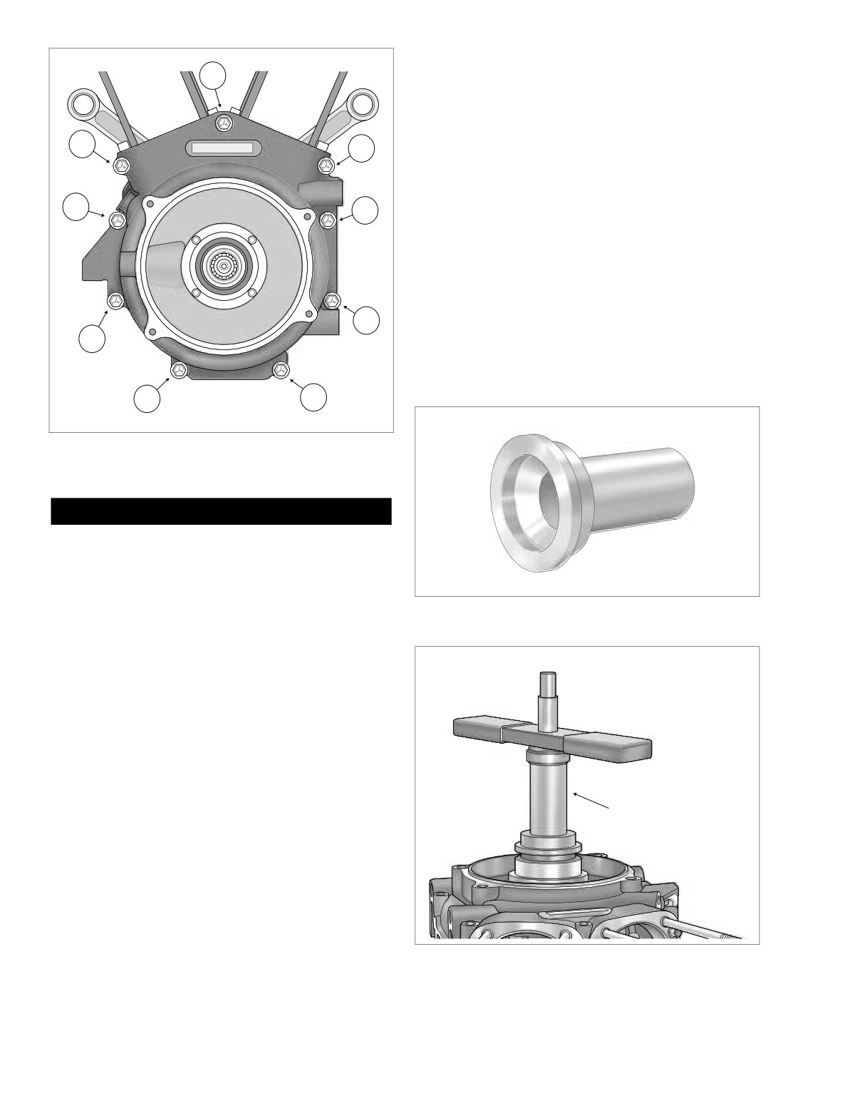
Figure 3-46. Crankcase Torque Sequence
(Left Side View)
CAUTION
O-rings that are missing, distorted, pinched or otherwise
damaged will result in either oil leakage or low oil pres-
sure. Use of the wrong O-ring will have the same results.
Since many O-rings are similar in size and appearance,
always use new O-rings keeping them packaged until
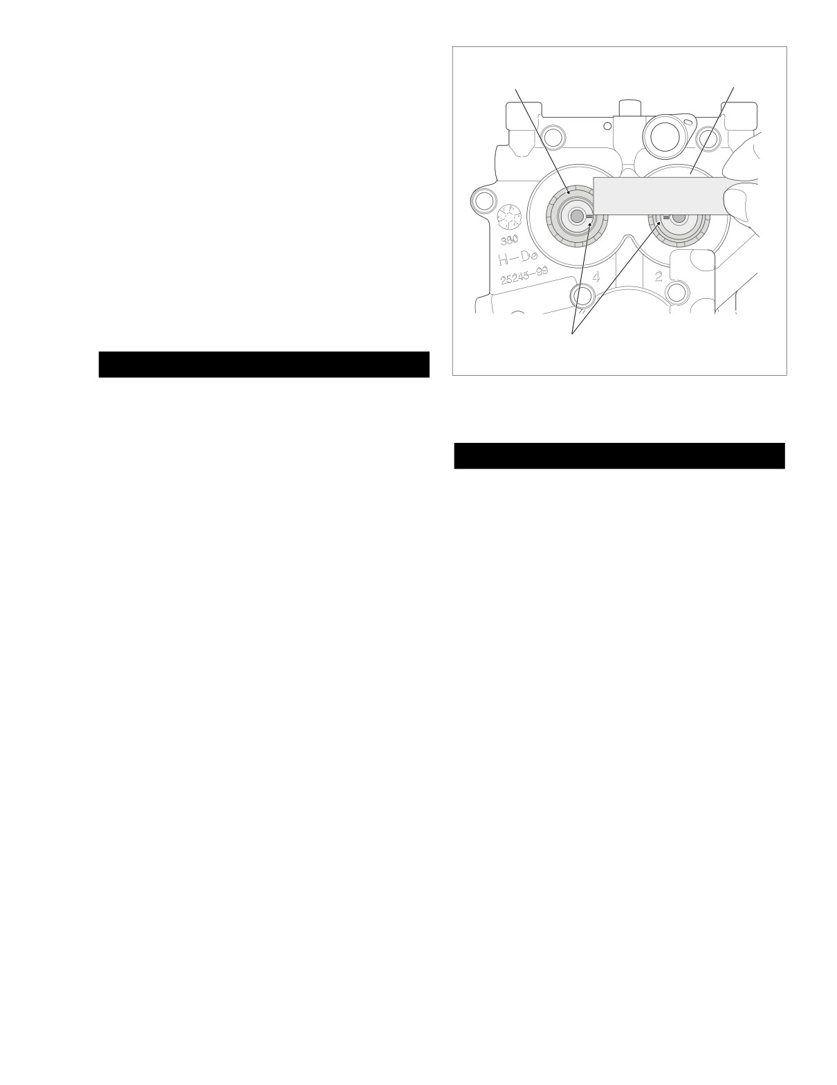
Figure 3-47. Sprocket Shaft Oil Seal Installer
use to avoid confusion.
(Part No. HD-39361A)
3. Install new O-rings over two ring dowels in split line face
of right case half.
4.
Apply a small bead of sealant approximately 0.056 inch
f1882x3x
(1.4 mm) wide to the split line face. For best results, use
High-Performance Sealant (gray), Part No. HD-99650-
02.
5. To prevent damage to the crankshaft bearing, place
CRANKSHAFT GUIDE (HD-42326A) over end of crank-
shaft. Mate case halves sliding bearing in right crank-
case half over end of crankshaft. Remove tool. See
Figure 3-45.
Sprocket Shaft
Oil Seal Installer
6. Start the nine crankcase bolts and tighten as follows:
a. Alternately turn each crankcase bolt until finger
tight.
b. Tighten the crankcase bolts to 10 ft-lbs (13.6 Nm) in
the sequence shown in Figure 3-46.
c. Following the same sequence, tighten each bolt to
15-19 ft-lbs (20.3-25.8 Nm).
Figure 3-48. Install
Oil Seal In Bore
3-48
2004 Touring: Engine
HOME
e. Slide Nice bearing and large flat washer over pilot
until contact is made with seal installer.
Rear
Front
Camshaft
Camshaft
f.
Thread handle onto pilot shaft.
g. Rotate handle in a clockwise direction until oil seal
installer makes firm contact with crankcase stator
mount. See Figure 3-48.
h. Remove handle, flat washer, Nice bearing, seal
installer and pilot from sprocket shaft.
9. Slide sprocket shaft spacer over end of sprocket shaft.
Push spacer into oil seal until seated against bearing
race.
10. Rotate crankcase in the engine stand so that the cam
cover flange is facing upward.
11. Install oil pump as follows:
Pin Stamped
f2068x3x
Timing Lines
CAUTION
Figure 3-49. Verify Alignment of Timing Lines
O-rings that are missing, distorted, pinched or otherwise
on Front and Rear Camshafts
damaged will result in either oil leakage or low oil pres-
sure. Use of the wrong O-ring will have the same results.
Since many O-rings are similar in size and appearance,
always use new O-rings keeping them packaged until
CAUTION
use to avoid confusion.
O-rings that are missing, distorted, pinched or otherwise
a. Install new O-ring on scavenge port stub of oil
damaged will result in either oil leakage or low oil pres-
pump housing. Apply a very thin film of clean H-D
sure. Use of the wrong O-ring will have the same results.
20W50 engine oil to O-ring before installation.
Since many O-rings are similar in size and appearance,
always use new O-rings keeping them packaged until
b. Slide oil pump housing onto crankshaft fitting O-ring
use to avoid confusion.
on scavenge port stub into crankcase bore at back
of cam compartment. Firmly push on scavenge port
g. Install new O-ring in groove on outboard side of oil
stub with thumb to be sure that it is snug in bore.
pump housing. See Figure 3-43. Apply a very thin
Inspect O-ring on stub to verify that it is not pinched
film of clean H-D 20W50 engine oil to O-ring before
or distorted.
installation.
c. Separate the gerotor gears into two sets, one wide
12. Install new O-ring in groove around oil feed hole in
(scavenge) and the other narrow (feed).
crankcase flange (directly below rear ring dowel). Install
new O-ring around blind hole in boss (directly above oil
NOTE
return hole in crankcase flange). Apply a thin film of H-D
Lubricate parts with clean H-D 20W50 engine oil during
20W50 engine oil to O-rings before installation.
assembly.
13. If not retracted, place cup of CAM CHAIN TENSIONER
UNLOADER (HD-42313) over spring coil of secondary
d. Fit the smaller of the wide gerotor gears into the
cam chain tensioner positioning finger on tool between
larger. Slide the wide gerotor set down the crank-
tensioner and shoe. Rotate tool in a counterclockwise
shaft until it bottoms in the oil pump housing.
direction inserting retention pin through hole in boss on
e. Slide the first of two separator plates down the
primary cam chain side of cam support plate. Pin
crankshaft until it contacts the wide gerotor set.
engages hooks on tensioner to hold it in the retracted
Install wave washer and second separator plate.
position. For best results, place cam support plate in a
vise using brass jaw inserts to prevent casting damage.
f.
Fit the smaller of the narrow gerotor gears into the
larger. Slide the narrow gerotor set down the crank-
14. Lubricate cam needle bearings with clean H-D 20W50
shaft until it contacts the separator plate.
engine oil.
2004 Touring: Engine
3-49
HOME
3
6
2
5
2
4
4
1
1
3
A
CAM SUPPORT PLATE
B
OIL PUMP
f1581b3x
f1581b3x
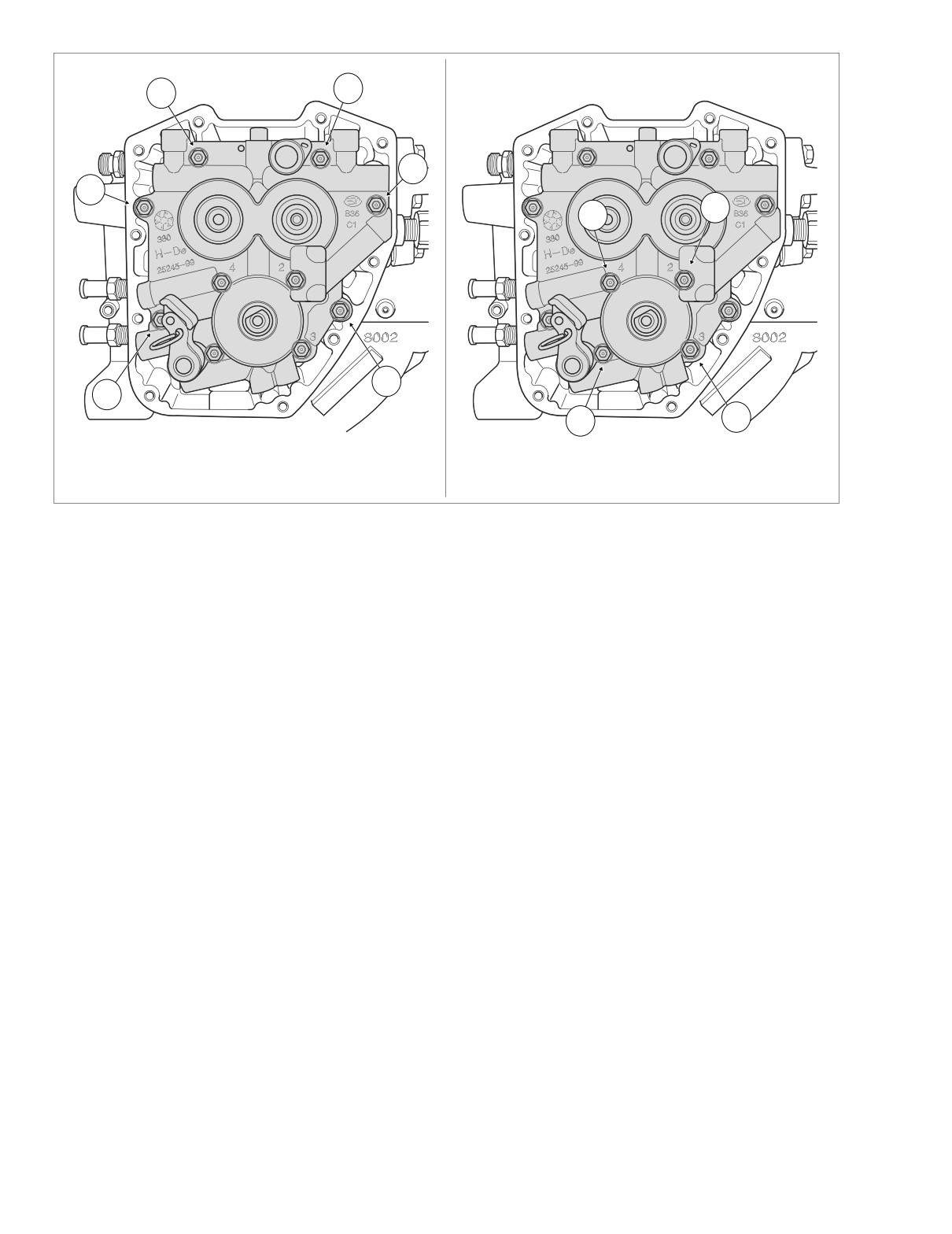
Figure 3-50. Cam Support Plate/Oil Pump Torque Sequence
15.
Using a straightedge, verify that the pin stamped timing
d. Alternately snug and then tighten the screws in
lines on the ends of the front and rear camshafts are in
holes 3 and 4 to 40-45 in-lbs (4.5-5.1 Nm).
alignment (although they may be somewhat difficult to
e. Remove the alignment tool from hole 1. Install the
see). See Figure 3-49. If necessary, rotate camshafts in
allen head socket screw and tighten to 40-45 in-lbs
order to make this observation.
(4.5-5.1 Nm).
16.
Aligning bushing in cam support plate with end of crank-
f.
Repeat step 18(e) to replace alignment tool in hole
shaft, slide cam support plate over crankshaft onto two
2 with allen head socket screw.
ring dowels in crankcase flange. Use a rubber mallet to
fully seat cam support plate on ring dowels.
g. Final tighten all four screws to 90-120 in-lbs (10.2-
13.6 Nm). Use the pattern shown in B of Figure 3-
17.
Install the six allen head socket screws (1/4 x 1 inch) to
50. Numbers cast adjacent to the bolt holes also
secure the cam support plate to the crankcase flange.
indicate the oil pump torque sequence.
Tighten screws to 90-120 in-lbs (10.2-13.6 Nm) in the
pattern shown in A of Figure 3-50.
NOTE
18.
Secure the cam support plate to the oil pump flange as
If only realigning the oil pump, first loosen all screws following
follows:
the pattern shown in B of Figure 3-50. Remove screws from
holes 1 and 2 and then follow the alignment procedure start-
a. Start two allen head socket screws (1/4 x 1 inch)
ing at step 18(b).
into holes 3 and 4. See B of Figure 3-50.
b. Obtain two ALIGNMENT TOOLS used to install lifter
19. Pull retention pin from hole in cam support plate to
guides on Evolution engines (HD-33443). Loosely
release secondary cam chain tensioner.
install alignment tools in holes 1 and 2.
20. Squeeze tabs and install chain guide between blocks
c. While rotating the engine, alternately snug and then
cast into cam support plate.
tighten the alignment tools to 40-45 in-lbs (4.5-5.1
21. Install primary cam sprocket spacer onto rear camshaft.
Nm).
22. If using the original cam support plate, camshafts, pri-
NOTE
mary cam sprocket, crank sprocket and flywheel assem-
For methods of engine rotation, see Section 3.9 TOP END
bly, then move to step 23. However, if any of these parts
OVERHAUL, DISASSEMBLY, step 7.
have been replaced, then proceed as follows:
3-50
2004 Touring: Engine
HOME
a. Install primary cam sprocket onto splines of rear
camshaft. Install long flange bolt with thicker flat
washer to secure sprocket to end of camshaft.
b. Install crank sprocket onto crankshaft. Install short
flange bolt with smaller diameter flat washer (that is,
washer from bulk inventory) to secure sprocket to
end of crankshaft.
NOTE
Use of smaller diameter flat washer with crank sprocket
flange bolt allows room on sprocket face for placement of
straightedge under step 22(e).
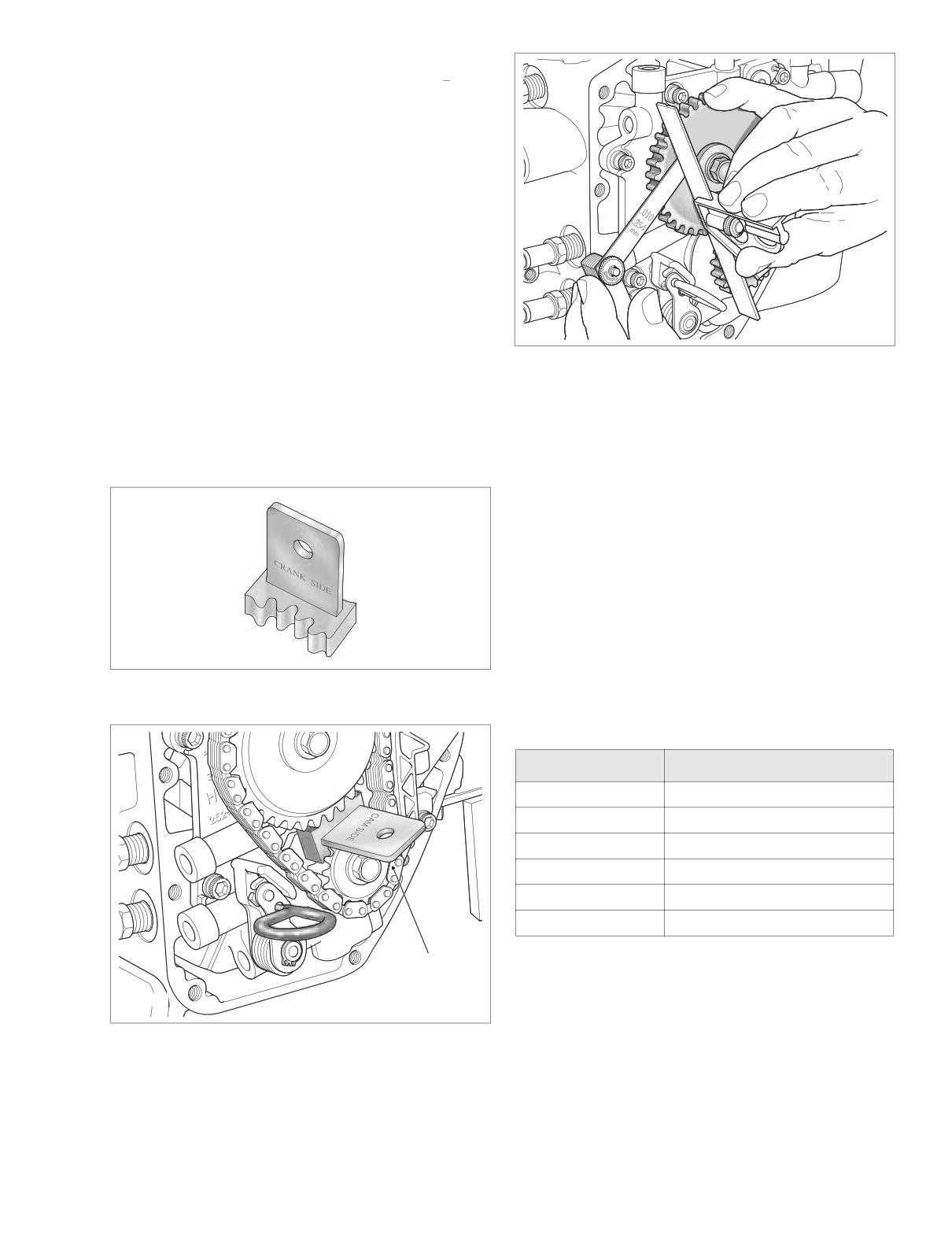
c. To prevent rotation, position the CRANKSHAFT/
CAMSHAFT SPROCKET LOCKING TOOL (HD-
f2142x3x
42314) between the crank and primary cam sprock-
ets. See Figure 3-52. The handle of the tool is
Figure 3-53. Check Alignment of Crank and
stamped “Crank” and “Cam” to ensure proper orien-
Primary Cam Sprocket Faces
tation. Tighten the crank and primary cam sprocket
flange bolts to
15 ft-lbs
(20.3 Nm). Remove the
sprocket locking tool.
e. Place a straightedge across the crank and primary
cam sprocket faces. Try to insert a 0.010 inch feeler
d. Push on rear camshaft to remove end play.
gauge between the straightedge and each sprocket
face. See Figure 3-53. If the feeler gauge does not
fit at either location, then proceed to step 22(f).
On the other hand, if the crank sprocket is “proud”
(that is, rises above the face of the primary cam
sprocket) more than 0.010 inch, remove the flange
bolt and primary cam sprocket, and noting the part
number stamped on the existing spacer, replace it
with the next larger size. See spacer sizes listed in
Table 3-4. Replace the spacer with the next smaller
size only if the primary cam sprocket is “proud”
(rises above the face of the crank sprocket) more
than 0.010 inch. Return to step 21 to repeat the
Figure 3-51. Crankshaft/Camshaft Sprocket Locking Tool
check with the new spacer installed.
(Part No. HD-42314)
Table 3-4. Primary Cam Sprocket Spacers
Spacer Size
H-D Part Number
0.287
25722-00
0.297
25723-00
0.307
25721-00
0.317
25719-00
0.327
25717-00
0.337
25725-00
Sprocket
f.
Remove both crank and primary cam sprockets.
Locking Tool
Discard smaller diameter flat washer obtained from
f2139x3x
bulk inventory.
Figure 3-52. Lock Crank and Primary Cam Sprockets
23. Install the primary cam chain and sprocket assembly as
Before Tightening Flange Bolts
follows:
2004 Touring: Engine
3-51
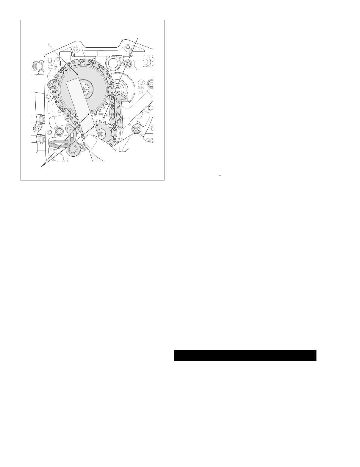
HOME
NOTE
Crank
If the punch marks are not in alignment, then the sprockets
Primary Cam
Sprocket
must be removed and reinstalled. The vehicle will not run
Sprocket
properly if the sprockets are misaligned by even one tooth.
NOTE
Both crank and primary cam sprocket flange bolts are spe-
cially hardened, while the flat washers are of a special diam-
eter and thickness. Therefore, use only genuine Harley-
Davidson parts when replacement is necessary. The crank
and primary cam sprocket flange bolts and flat washers are
NOT interchangeable.
25. Install crank sprocket and primary cam sprocket flange
bolts and flat washers as follows:
NOTE
Exercise caution to avoid mixing oil on washer with thread-
locker on bolt or sealing integrity may be compromised.
a.
Apply a thin film of clean H-D 20W50 engine oil to
both sides of flat washers.
b.
Install thinner flat washer on short flange bolt.
Punch Marks
f2138x3x
c.
Install thicker flat washer on long flange bolt.
d.
Apply Loctite Primer
7649
(P/N
98968-99) to
Figure 3-54. Verify Alignment of Crank and
threads of flange bolts.
Primary Cam Sprocket Punch Marks
e.
Apply one drop of Loctite High Strength Thread-
locker 262 (red) to threads of flange bolts.
a. Place the primary cam sprocket in the cam chain.
Hold the sprocket allowing the chain to hang loose.
f.
Install short flange bolt with thinner flat washer to
Rotate the sprocket so that the punch mark on the
secure crank sprocket to end of crankshaft.
sprocket root faces straight downward.
g.
Install long flange bolt with thicker flat washer to
secure primary cam sprocket to end of camshaft.
NOTE
To maintain the original direction of rotation, verify that the
h.
Position CRANKSHAFT/CAMSHAFT SPROCKET
colored mark placed on the chain link and crank sprocket is
LOCKING TOOL (HD-42314) between the crank
facing away from the cam support plate during installation.
and primary cam sprockets to prevent rotation. See
Figure 3-52. The handle of the tool is stamped
b. Place the crank sprocket in the opposite end of the
“Crank” and “Cam” to ensure proper orientation.
chain with the punch mark on the sprocket tooth fac-
i.
Alternately tighten the crank and primary cam
ing straight upward.
sprocket flange bolts to 15 ft-lbs (20.3 Nm).
c. Maintaining the position of the sprockets on the
j.
Loosen each flange bolt one full turn.
chain with the punch marks in alignment, start the
primary cam sprocket onto the splines of the rear
k.
Tighten the crank sprocket flange bolt to 24 ft-lbs
camshaft. Apply a thin film of clean H-D 20W50
(32.5 Nm).
engine oil to the splines before installation.
l.
Tighten the primary cam sprocket flange bolt to 34
d. Maintaining the position of the crank sprocket on the
ft-lbs (46.1 Nm).
chain, rotate the primary cam sprocket in a clock-
m.
Remove the sprocket locking tool.
wise direction until the flat on the crank sprocket is
aligned with the flat on the crankshaft. Install the
crank sprocket.
1CAUTION
24. Rotate the primary cam sprocket in a clockwise direction
Ease the primary cam chain tensioner into the unloaded
until the punch mark on the root is aligned with the
position using the proper tool. Do not pull the retention
punch mark on the crank sprocket tooth. Lay a straight-
pin to unload the tensioner or the pin may be damaged.
edge across the centerline of the crank and primary cam
Furthermore, if the tensioner should contact fingers or
sprocket flange bolt holes to verify that the punch marks
other parts of the hand, minor or moderate injury may
are in alignment. See Figure 3-54.
occur.
3-52
2004 Touring: Engine
HOME
26. Hold the retracted primary cam chain tensioner with the
CAM CHAIN TENSIONER UNLOADER (HD-42313),
7
6
pull retention pin from hole in cam support plate and
Torque: 125-155 in-lbs
4
ease the assembly into the unloaded position.
1
27. Apply clean H-D 20W50 engine oil to crank and primary
cam sprockets.
CAUTION
Before cam cover installation, verify cleanliness of blind
holes in the crankcase flange. Tightening screws with
9
dirt, water or oil in the holes can cause the casting to
crack or break. Damage to the casting requires replace-
10
ment of the right crankcase half.
28. Align holes in new cam cover gasket with those in the
5
crankcase flange.
8
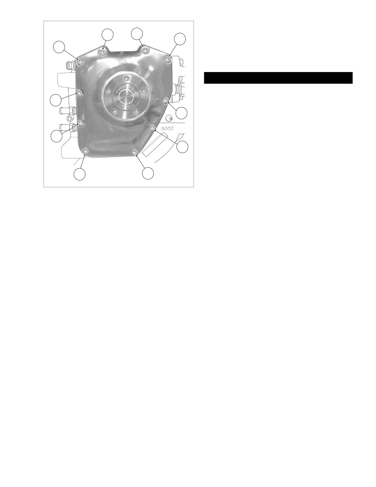
29. Install the cam cover using ten allen head socket screws
(1/4 x 1-1/4 inches). Alternately tighten screws to 125-
155 in-lbs (14.1-17.5 Nm) following the pattern shown in
Figure 3-55.
3
2
f1616b3x
30. If performing a complete engine overhaul, see Section
3.9 TOP END OVERHAUL, ASSEMBLY, steps 1-39. If
Figure 3-55. Cam Cover Torque Sequence
only cam compartment components were serviced, just
see steps 28-37.
2004 Touring: Engine
3-53
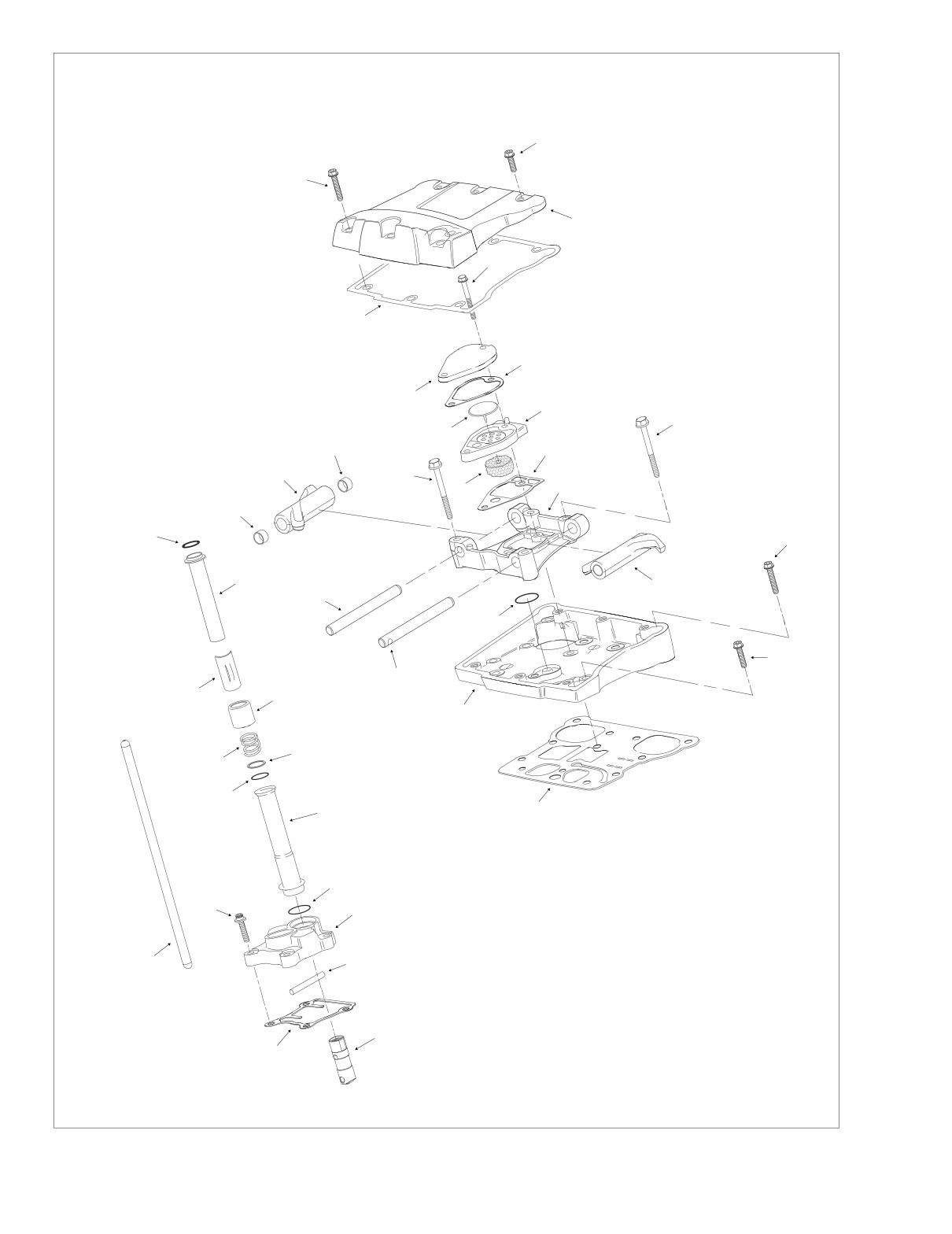
HOME
Legend:
1.
Bolt
24.
Upper Push Rod Cover
2.
Bolt
25.
Spring Cap Retainer
3.
Rocker Cover
26.
Spring Cap
2
4.
Rocker Cover Gasket
27.
Spring
5.
Breather Bolt
28.
Flat Washer
6.
Breather Cover
29.
O-Ring
7.
Breather Cover Gasket
1
30.
Lower Push Rod Cover
8.
Umbrella Valve
31.
O-Ring
9.
Breather Baffle
32.
Lifter Cover Screw
10.
Filter Element
3
33.
Lifter Cover
11.
Breather Baffle Gasket
34.
Anti-Rotation Pin
12.
Rocker Arm Bolt
35.
Lifter Cover Gasket
13.
Rocker Arm Support Plate
5
36.
Hydraulic Lifter
14.
Rocker Arm Bushing
37.
Push Rod
15.
Rocker Arm
16.
Rocker Arm Shaft
17.
Rocker Arm
18.
Breather Baffle O-Ring
4
19.
Rocker Housing Bolt
20.
Rocker Housing Bolt
21.
Rocker Housing
7
22.
Rocker Housing Gasket
23.
O-Ring
6
9
12
8
14
11
15
12
10
13
14
23
19
24
17
16
18
20
16
25
26
21
28
27
29
30
22
31
32
33
37
34
36
35
f2239x3x
Figure 3-56. Rocker Arm/Breather/Lifter Assemblies (Exploded View)
3-54
2004 Touring: Engine
HOME
SUBASSEMBLY SERVICE AND REPAIR
3.11
TOP END
f2176x3x
1
BREATHER ASSEMBLY
2
Removal
1.
See Section 3.9 TOP END OVERHAUL, DISASSEM-
3
BLY, steps 1-8.
Disassembly
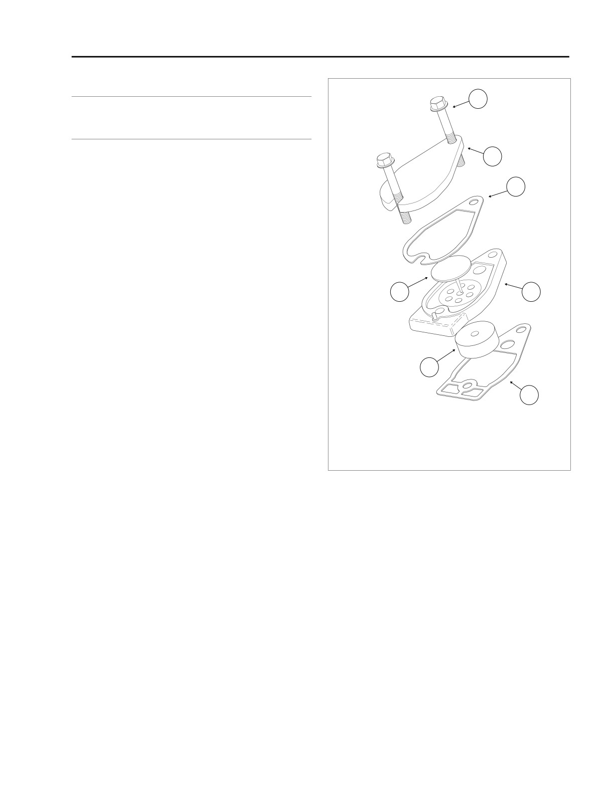
1. Remove two bolts and lift breather assembly from rocker
arm support plate. See Figure 3-57.
2. Remove the breather cover and gasket. Remove the
breather baffle and gasket. Discard gaskets.
3. Pull filter element from bore on inboard side of breather
4
5
baffle. Pull stem of umbrella valve from hole at top of
breather baffle. Discard both filter element and umbrella
valve.
Cleaning and Inspection
6
1. Clean all parts in a non-volatile cleaning solution or sol-
vent.
7
2. Thoroughly dry all parts with low pressure compressed
air.
1.
Bolt
3. Set a straightedge diagonally across the length of the
2.
Breather Cover
5.
Breather Baffle
breather cover intersecting the opposite corners of the
3.
Cover Gasket
6.
Filter Element
gasket surface. Slide a feeler gauge beneath the
4.
Umbrella Valve
7.
Breather Baffle Gasket
straightedge to check the breather cover for warpage.
Repeat the step checking the opposite diagonal. Discard
Figure 3-57. Breather Assembly
the breather cover if any low spot exceeds 0.005 inch
(0.13 mm).
4. Repeat step
3 to inspect the gasket surface of the
breather baffle for flatness. Discard the breather baffle if
any low spot exceeds 0.005 inch (0.13 mm).
3.
Place breather baffle gasket on a clean flat surface.
Aligning holes, place breather baffle, cover gasket and
Assembly
breather cover on top. Slide two screws through stackup
to keep assembly together until time of installation.
1.
Insert stem of new umbrella valve through center hole at
top of breather baffle. Carefully pull rubber bead on stem
through hole in baffle. Use denatured alcohol or glass
cleaner to lubricate stem, if necessary. Verify that rubber
Installation
bead is pulled completely through hole and resides on
1. See Section 3.9 TOP END OVERHAUL, ASSEMBLY,
bottom side of baffle.
steps 31-39.
2.
Press new filter element into bore at bottom of baffle.
Hole in filter element accommodates umbrella valve
stem.
2004 Touring: Engine
3-55
HOME
3.
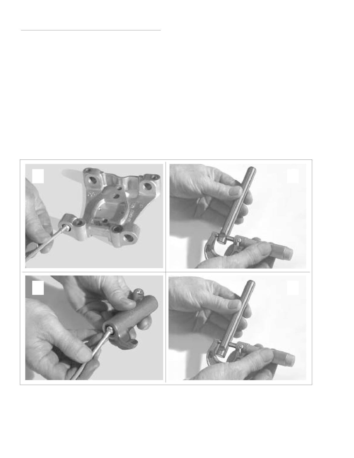
Remove the rocker arms from the rocker arm support
ROCKER ARM ASSEMBLY
plate. Mark the rocker arms to indicate location.
Removal
Cleaning and Inspection
1. See Section 3.9 TOP END OVERHAUL, DISASSEM-
BLY, steps 1-9.
1.
Clean all parts in a non-volatile cleaning solution or sol-
vent. Thoroughly dry with low pressure compressed air.
Disassembly
2.
Check rocker arms for uneven wear or pitting where con-
tact is made with the valve stem tips. Check for concave
1.
Remove the four bolts from the rocker arm support plate.
wear where rocker arms contact the push rod ends.
If necessary, slightly wiggle the two bolts on the push rod
Replace rocker arm if excessive wear is found at either
side (right) to disengage them from the notches in the
location.
rocker arm shafts.
3.
Verify that oil holes in rocker arms and rocker arm sup-
2.
Using a hammer and brass drift, tap left side of rocker
port plate are clean and open.
arm shafts so that the notched ends exit the rocker arm
support plate first. Mark the shafts so that they are
4.
Inspect rocker arm shafts for scratches, burrs, scoring or
installed in their original locations at time of assembly.
excessive wear. Replace as necessary.
A
B
C
D
Figure 3-58. Measure Rocker Arm Assembly for Wear
3-56
2004 Touring: Engine
HOME
5.
Measure the inside diameter of the rocker arm support
plate bore. See A of Figure 3-58. Measure the outside
Remove Bushings.
diameter of the rocker arm shaft where it fits in the bore.
See B of Figure 3-58. Repeat the measurement on
opposite side of support plate and shaft. Replace the
shaft or support plate if any measurement equals or
exceeds 0.0035 inch (0.089 mm).
Driver
Discarded Shaft
6.
Measure the inside diameter of the rocker arm bushing.
See C of Figure 3-58. Measure the outside diameter of
the rocker arm shaft where it rides in the bushing. See D
of Figure 3-58. Repeat the measurement on opposite
side of rocker arm and shaft. Replace the shaft or bush-
ings if any measurement equals or exceeds 0.0035 inch
(0.089 mm).
7.
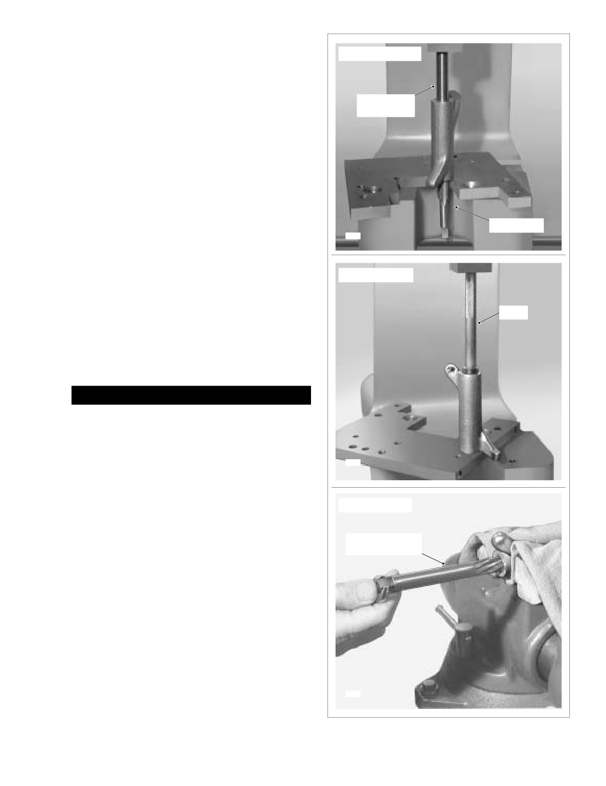
To replace rocker arm bushings, proceed as follows:
NOTE
9/16”-18 Tap
Remove, install and ream one bushing at a time.
6916
a. Obtain a 9/16”-18 (14.29 mm) tap. Turn tap into
bushing until tight. Place rocker arm under ram of
arbor press with tap at bottom. Slide a discarded
Install Bushings.
rocker arm shaft through open end of rocker arm
until contact is made with tap. Using shaft as driver
(and untapped bushing as pilot), press against shaft
until both tap and bushing are free. See upper
Driver
frame of Figure 3-59.
b. Using a suitable driver, press new bushing into side
of rocker arm until flush with casting. See center
frame of Figure 3-59. Be sure to orient bushing so
that split line faces top of rocker arm.
CAUTION
Never back reamer out of rocker arm or new bushing will
be damaged.
c. Lock rocker arm in a vise using brass jaw inserts or
shop towels to prevent casting damage. Insert
6922
tapered end of ROCKER ARM BUSHING REAMER
(HD-94804-57) into old bushing in rocker arm. Note
that old bushing on drive side of reamer serves as
pilot. See lower frame of Figure 3-59. Rotate reamer
Ream Bushings.
until new bushing on far side is reamed, and then
continuing in the same direction, draw drive side of
reamer from new bushing.
Bushing Reamer
d. Repeat steps 7(a) thru 7(c) to remove, install and
Part No. HD-94804-57
ream second bushing.
Assembly
1. Place the rocker arms into position on the rocker arm
support plate.
2. Push the un-notched ends of the rocker arm shafts into
the right side of the support plate and then into the
rocker arms. As they approach their fully installed posi-
tions, rotate the shafts so that the notches are aligned
with the bolt holes in the support plate.
6923
Figure 3-59. Replace Rocker Arm Bushings
2004 Touring: Engine
3-57
HOME
3.
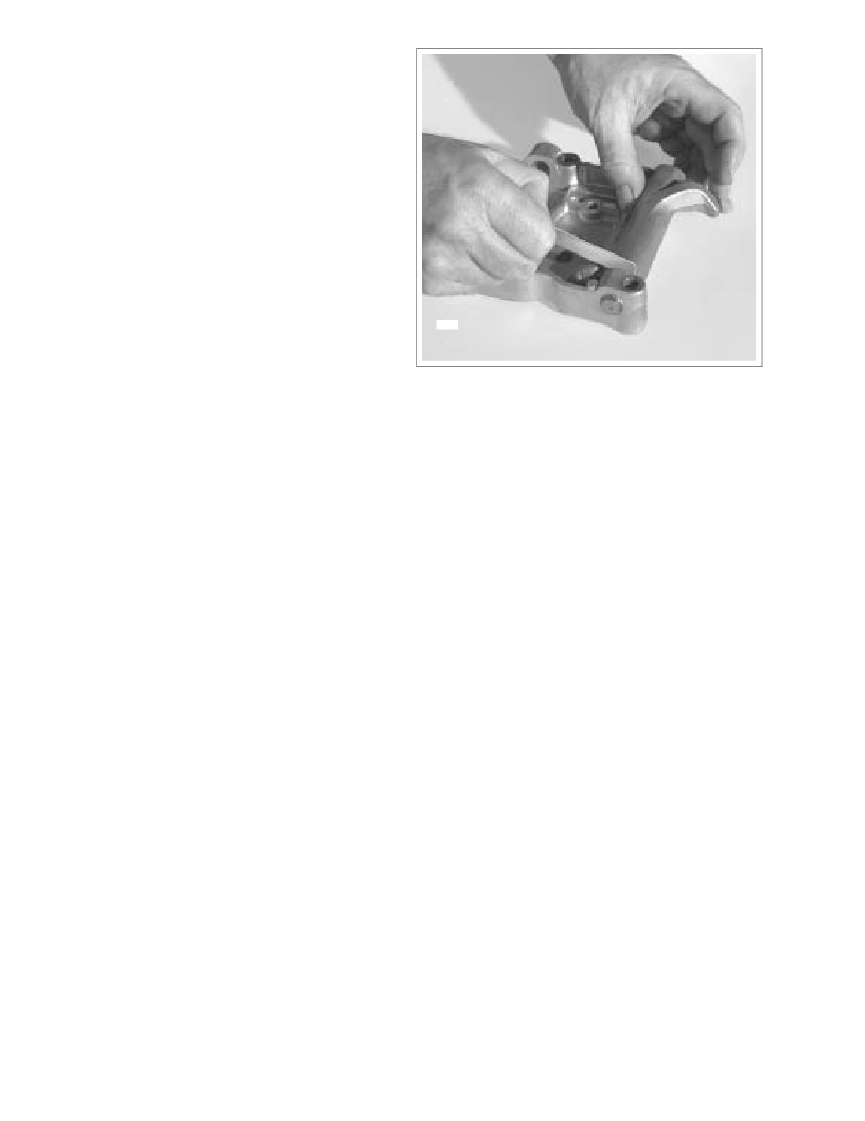
To check for proper end play, insert a feeler gauge
between the rocker arm and support plate. See Figure 3-
60. Repeat measurement on other rocker arm. Replace
the rocker arm, rocker arm support plate, or both if end
play exceeds 0.025 inch (0.635 mm).
4.
Install the four bolts in the rocker arm support plate. For
proper assembly, remember that the two bolts on the
push rod side (right) must engage the notches in the
rocker arm shafts.
Installation
1. See Section 3.9 TOP END OVERHAUL, ASSEMBLY,
steps 31-39.
6917
Figure 3-60. Check End Play
3-58
2004 Touring: Engine
HOME
PUSH RODS/LIFTERS/COVERS
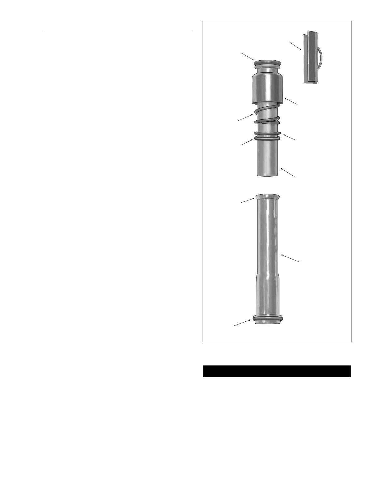
Spring Cap
Retainer
O-Ring
Removal
Small
1. See Section 3.9 TOP END OVERHAUL, DISASSEM-
BLY, steps 1-14.
Disassembly
1. With the exception of the lifter covers, all parts should
have been disassembled and marked during the
Spring Cap
removal procedure. Disassemble the lifter covers as fol-
lows:
Spring
a. Separate upper and lower push rod covers.
b. Remove O-ring from seat at bottom of lower push
Flat
O-Ring
rod cover. Discard O-ring.
Washer
Intermediate
c. Remove O-ring from seat at top of upper push rod
cover. Slide O-ring, flat washer, spring and spring
cap from body of upper push rod cover. Discard O-
rings.
Upper
Push Rod
Cover
Cleaning and Inspection
Flared End
1. Scrape old gasket material from the lifter cover flange.
Old gasket material left on mating surfaces will cause
leaks.
2. With the exception of the hydraulic lifters, clean all parts
in a non-volatile cleaning solution or solvent. Verify that
the O-ring seats and contact surfaces of the push rod
covers are completely clean.
Lower
3. Thoroughly dry all parts with low pressure compressed
Push Rod
air. Verify that all oil holes are clean and open.
Cover
4. Verify that the hydraulic lifter rollers turn freely and are
free of flat spots, scuff marks and pitting. If flat spots
exist, examine the cam lobe on which the lifter operates.
5. Inspect the lifter socket for signs of wear. Verify that the
plunger of the hydraulic lifter is fully extended up against
the C-clip. Use index finger to pump plunger to verify
O-Ring
lifter operation.
Large
f1584x3x
6. Examine the push rods. Replace any push rods that are
bent, dented, broken or discolored. Replace the rod if
Figure 3-61. Push Rod Cover Assembly
the ball ends show signs of excessive wear or damage.
7. Cover all parts with a clean plastic sheet to protect them
CAUTION
from dust and dirt.
O-rings that are missing, distorted, pinched or otherwise
Assembly
damaged will result in either oil leakage or low oil pres-
sure. Use of the wrong O-ring will have the same results.
1. With the exception of the lifter covers, all parts will be
Since many O-rings are similar in size and appearance,
assembled during the installation procedure. Assemble
always use new O-rings keeping them packaged until
the lifter covers as follows:
use to avoid confusion.
2004 Touring: Engine
3-59
HOME
a. Obtain three new o-rings- small, intermediate and
d. Fit the straight end of the upper push rod cover into
large.
the flared end of the lower push rod cover.
b. Install small O-ring on seat at the top of the upper
e. Install large O-ring on seat at bottom of lower push
push rod cover.
rod cover.
NOTE
Apply a very thin film of clean H-D 20W50 engine oil to O-
Installation
rings before installation.
1.
See Section 3.9 TOP END OVERHAUL, ASSEMBLY,
c. Slide the spring cap, spring, flat washer and inter-
steps 25-39.
mediate size O-ring onto the body of the upper push
rod cover. Move parts up body until spring cap con-
tacts upper O-ring seat.
3-60
2004 Touring: Engine
HOME
NOTES
2004 Touring: Engine
3-61
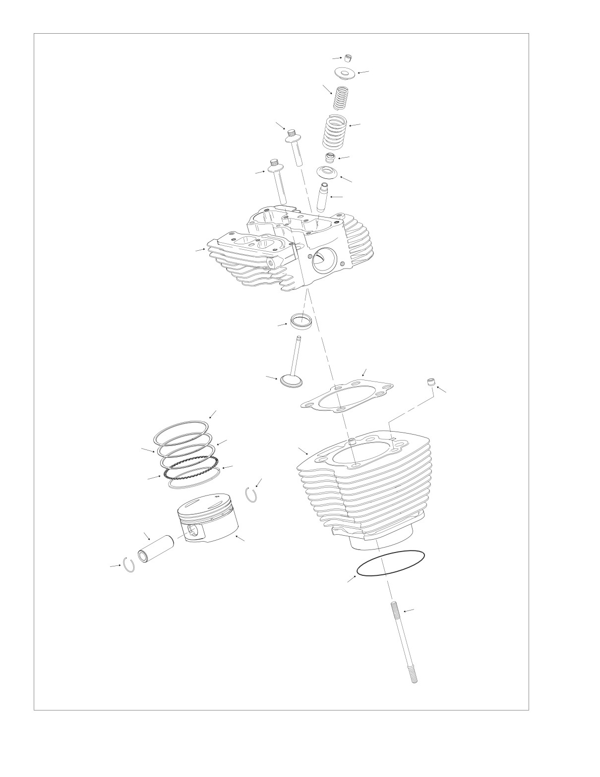
HOME
Legend:
1
1.
Tapered Keepers
2
2.
Spring Retainer
3
3.
Inner Spring
4.
Outer Spring
5.
Valve Stem Seal
6.
Spring Seat
7.
Valve Guide
8
8.
Cylinder Head Bolt
4
9.
Cylinder Head Bolt
10.
Cylinder Head
11.
Valve Seat
12.
Valve
5
13.
Cylinder Head Gasket
14.
Cylinder
9
15.
Ring Dowel
6
16.
O-Ring Seal
17.
Cylinder Stud
7
18.
Piston
19.
Piston Pin
20.
Circlip
21.
Top Compression Ring
22.
Second Compression Ring
23.
Oil Rail
24.
Oil Rail Spacer
10
11
13
12
15
21
23
22
14
23
20
24
19
18
20
16
17
f21332x3x
Figure 3-62. Cylinder Head/Cylinder/Piston Assemblies (Exploded View)
3-62
2004 Touring: Engine
HOME
CYLINDER HEAD
Removal
1. See Section 3.9 TOP END OVERHAUL, DISASSEM-
BLY, steps 1-11 and 15-19.
Disassembly
1. Before proceeding with the disassembly procedure,
determine if cylinder head reconditioning is necessary.
Proceed as follows:
Figure 3-65. Valve Spring Compressor
a. Raise valve ports of cylinder head to strong light
(Part No. HD-34736B)
source. If light is visible around edges of seats, then
move to step 2 to recondition cylinder head.
f1648x3x
b. Fill ports at top of cylinder head with solvent. Wait
ten full seconds and then check for leakage into
combustion chamber. If solvent leakage into com-
bustion chamber is evident, then move to step 2 to
recondition cylinder head.
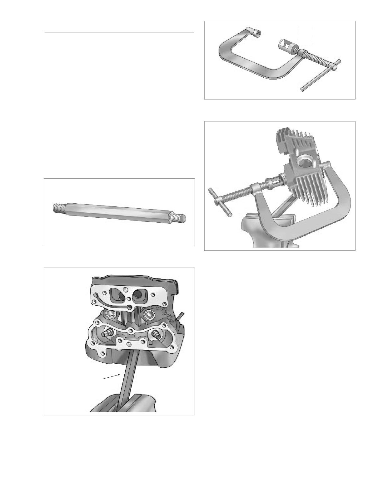
14mm End
12mm End
Figure 3-63. Cylinder Head Holding Fixture
Figure 3-66. Compress Valve Springs
(Part No. HD-39786)
f1658x3x
2.
Obtain the CYLINDER HEAD HOLDING FIXTURE (HD-
39786) and proceed as follows:
a. Note that both ends of the fixture are threaded, one
end at 14mm and the other at 12mm. Thread the
12mm end of the tool into the spark plug hole of the
cylinder head.
b. Clamp tool in vise at a 45 degree angle (or one that
offers a comfortable working position). See Figure
3-64.
3.
Obtain the VALVE SPRING COMPRESSOR
(HD-
34736B) and proceed as follows:
a. Place tool over cylinder head so that the blunt end is
centered on the valve head and adapter at end of
forcing screw is seated on the valve spring retainer.
Cylinder Head
See Figure 3-66.
Holding Fixture
b. Rotate forcing screw to compress valve springs.
c. If spring retainer has not broken free of tapered
keepers, give head of tool a sharp tap with a soft
mallet. Using magnetic rod or small screwdriver,
Figure 3-64. Install Cylinder Head Holding Fixture in Vise
remove the keepers from the valve stem groove.
2004 Touring: Engine
3-63
HOME
d. Rotate forcing screw to release the valve spring
4.
Thoroughly clean the cylinder head, spring retainers,
compression.
tapered keepers, valves, inner and outer valve springs
and spring seats in a non-volatile cleaning solution or
4.
Remove the spring retainer and inner and outer valve
solvent. Follow up with a thorough wash in hot soapy
springs.
water. Blow dry with compressed air.
5.
Slide the valve from the valve guide.
Inspection
6.
Using pliers, twist and remove the valve stem seal from
the top of the valve guide. Discard the valve stem seal.
Cylinder Head
7.
Remove the spring seat from the cylinder head.
1.
Check for scratches and nicks on all gasket sealing sur-
faces.
8.
Mark the bottom of the valve “F(ront)” or “R(ear)” to indi-
cate the cylinder head from which it was removed. Also,
2.
With the combustion chamber side facing upward, set a
separate and tag tapered keepers, valve springs, spring
straightedge diagonally across the length of the cylinder
retainers and spring seats so that they are installed on
head intersecting the upper and lower corners of the
the same valve at time of assembly.
gasket surface. Slide a feeler gauge beneath the
straightedge to check the head for warpage. Checking
9.
Repeat steps 3-8 to remove the other valve components.
the opposite diagonal, repeat the procedure to verify that
the gasket surface is flat (especially if a head gasket was
10. Release the cylinder head holding fixture from the vise
blown). Discard the head if any low spot is 0.005 inch
and then remove the tool from the spark plug hole.
(0.13 mm) or greater.
NOTE
Cleaning and Inspection
For good results, use one of the CYLINDER TORQUE
PLATES (HD-42324A) in lieu of the straightedge. Lay the
Cleaning
upper plate flat on the machined surface of the head. As a
preliminary check, see if the plate rocks from side to side. A
1.
Remove old gasket material from cylinder head. Gasket
head on which the plate rocks is immediately suspect. Insert
material left on sealing surfaces will cause leaks.
a feeler gauge between the plate and head at various loca-
2.
Remove all carbon deposits from combustion chamber
tions to see if warpage exceeds above specification.
and machined surfaces of cylinder head. Exercise cau-
3.
Verify that oil passageways are open and clean.
tion to avoid removing any metal material. For best
results, use an air tool with a worn wire brush. Scraping
Valve Guides
may result in scratches or nicks.
1.
Inspect external surfaces for cracks
(particularly the
3. To soften stubborn deposits, soak the cylinder head in a
combustion chamber side). Replace the guide if any
chemical solution, such as GUNK HYDRO-SEAL or
cracks are found.
other carbon and gum dissolving agent. Repeat step 2
as necessary.
2.
To verify cleanliness of valve guides, lightly hone bore
using the VALVE GUIDE HONE (HD-34723) and then
scrub with the VALVE GUIDE CLEANING BRUSH (HD-
CAUTION
34751) to remove any dust or debris. Polish the valve
stem with fine emery cloth or steel wool to remove car-
Do not use glass or sand to bead blast surfaces exposed
bon buildup, and then check valve stem to guide clear-
to the engine oil. Bead blasting materials become lodged
ance as follows:
in the pores of the casting where they cannot be
removed through ordinary cleaning methods. Only after
Carefully measure the inside diameter of the valve guide
the engine is put into use will heat expansion cause this
using an inside ball micrometer. Measure the outside
material to be released, and the resulting oil contamina-
diameter of the valve stem with an outside micrometer.
tion will accelerate wear and lead to engine failure. If
The valve stem and/or guide are excessively worn if the
bead blasting must be employed, use wallnut shells or
clearance exceeds the limits shown in Table 3-5. Repeat
other soft non-damaging abrasive that can be digested
measurements with a new valve to determine if the
in the engine oil.
guide must be replaced.
Table 3-5. Service Wear Limits
CAUTION
Valve
Valve Stem to Guide Clearance
Be aware that bead blasting materials may also enter
threaded holes adversely affecting fastener engagement
Intake
0.0035 inch (0.089 mm)
and torque indication. Carefully cover all threaded holes
Exhaust
0.0040 inch (0.102 mm)
if bead blasting is employed.
3-64
2004 Touring: Engine
HOME
Tapered Keepers
1.
Inspect parts for damage or rust pits. Replace as neces-
Intake Seat
sary.
Adapter
2.
Inspect inboard side of tapered keepers for excessive
Part No. HD-39782A-3
Cylinder Head
wear. Upraised center must be pronounced and fit
Support Stand
snugly in valve stem groove. Place keepers into groove
and verify that they grip tightly without sliding.
Valve Seats
1.
Inspect seats for cracking, chipping or burning. Replace
seats if any evidence of these conditions are found.
2.
Check seats for recession by measuring valve stem pro-
Exhaust Seat
trusion. See VALVE AND SEAT REFACING in this sec-
Adapter
Part No. HD-39782A-4
tion, steps 5-6.
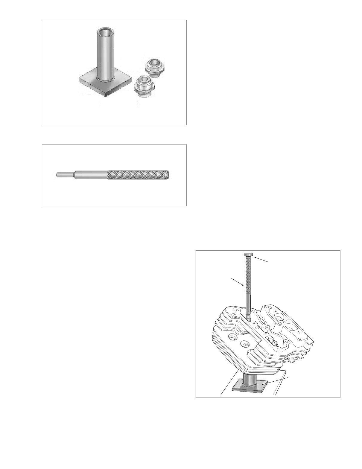
Figure 3-67. Cylinder Head Support Stand
VALVE GUIDE REPLACEMENT
(Part No. HD-39782A)
Removal
NOTE
If valve guide replacement is necessary, always install new
guide before refacing valve seat.
1.
Obtain the CYLINDER HEAD SUPPORT STAND (HD-
39782A) and proceed as follows:
a. Insert sleeve of intake or exhaust seat adapter into
tube at top of support stand. See Figure 3-67.
b. Position cylinder head so that valve seat is centered
Figure 3-68. Valve Guide Driver (Part No. HD-34740)
on seat adapter. Support stand ensures that valve
guide and seat are perpendicular. If perpendicular-
Valves
ity is not achieved, the cylinder head valve guide
bore will be damaged during the press procedure.
1. Replace the valve if there is evidence of burning or
cracking.
2. Inspect the end of the valve stem for pitting or uneven
f1681x3x
wear. Replace the valve if either of these conditions are
Ram
found.
Valve Guide
Driver
3. Inspect for burrs around the valve stem keeper groove.
Remove burrs with a fine tooth file if found.
4. To determine if the valve stem is excessively worn, see
INSPECTION, VALVE GUIDES, step 2.
Valve Springs
1. Inspect springs for broken or discolored coils. Replace
springs if either of these conditions are found.
2. Set the intake and exhaust valve springs on a level sur-
face and use a straightedge to check for proper square-
ness and height.
3. Check free length of inner and outer springs using a dial
Cylinder Head
vernier caliper or load test with the VALVE SPRING
Support Stand
TESTER (HD-96796-47). Replace springs if free length
or compression force do not meet specifications. See
Section 3.1 SPECIFICATIONS.
Figure 3-69. Remove Valve Guide
2004 Touring: Engine
3-65
HOME
Installation
1.
Measure the outside diameter of a new standard valve
Valve Guide
guide, and then measure the cylinder head valve guide
Driver
bore. The valve guide should be 0.0020-0.0033 inch
(0.051-0.084 mm) larger than the bore.
If clearance is not within specification, then select one of
the following oversize guides - 0.001 inch (0.025 mm),
0.002 inch (0.05 mm) or 0.003 inch (0.08 mm).
Valve Guide
NOTE
Installer Sleeve
Since some material is typically removed when the guide is
pressed out, it is normal to go to the next larger size for the
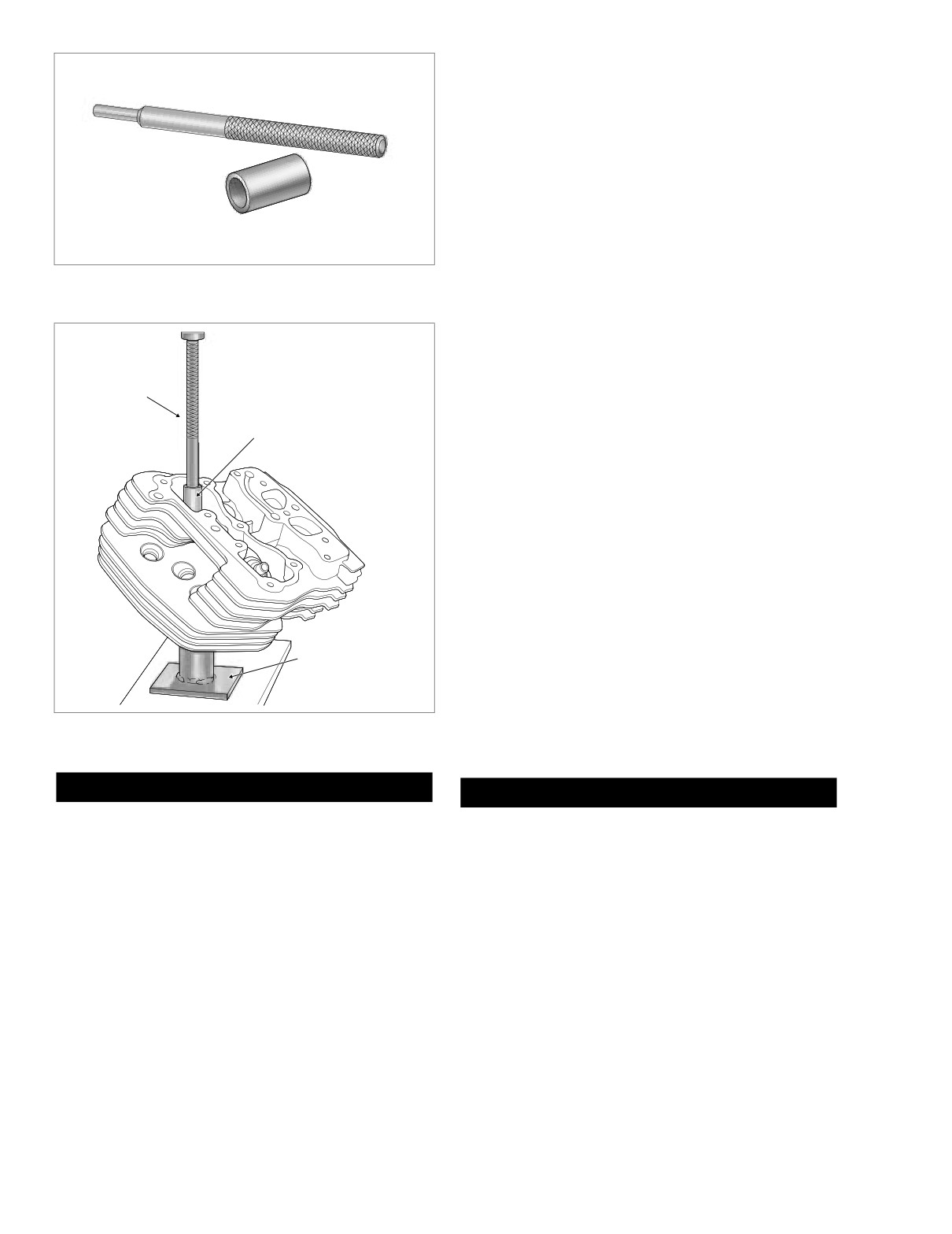
Figure 3-70. Valve Guide Driver (Part No. HD-34740) and
proper interference fit.
Valve Guide Installer Sleeve (Part No. HD-34731)
2.
Measure cylinder head bore and outside diameter of
selected oversize guide to verify correct interference fit.
f1680x3x
3.
Obtain the CYLINDER HEAD SUPPORT STAND (HD-
39782A), VALVE GUIDE DRIVER
(HD-34740) and
Valve Guide
VALVE GUIDE INSTALLER SLEEVE (HD-34731). Pro-
Driver
ceed as follows:
Valve Guide
Installer Sleeve
a. Insert sleeve of intake or exhaust seat adapter into
tube at top of support stand. Position cylinder head
so that valve seat is centered on seat adapter. Sup-
port stand ensures that valve guide and seat are
perpendicular. If perpendicularity is not achieved,
cylinder head valve guide bore will be damaged dur-
ing the press procedure.
b. Apply Vaseline to lightly lubricate external surfaces
of valve guide. Spread lubricant so that thin film cov-
ers entire surface area.
c. At top of cylinder head, start valve guide into bore.
d. Place installer sleeve over valve guide, and then
Cylinder Head
insert tapered end of valve guide driver into installer
Support Stand
sleeve.
e. Center valve guide driver under ram of arbor press
and apply pressure only until valve guide is started
Figure 3-71. Install Valve Guide
in bore and then back off ram slightly to allow guide
to center itself. See Figure 3-71.
CAUTION
CAUTION
Do not press out the valve guide from the bottom of the
Always back off ram to allow the valve guide to find cen-
cylinder head. Carbon buildup on the combustion cham-
ter. Pressing guide into cylinder head in one stroke can
ber side of the guide can deeply gouge the cylinder head
bend driver, break guide, distort cylinder head casting
bore diminishing the likelihood of achieving the proper
and/or damage cylinder head valve guide bore.
interference fit and possibly requiring replacement of
f.
Verify that support stand and driver are square.
the cylinder head casting.
Center driver under ram and press valve guide fur-
ther into bore, but then back off ram again to allow
2.
At the top of the cylinder head, insert VALVE GUIDE
valve guide to find center.
DRIVER (HD-34740) into valve guide bore until stopped
by shoulder.
g. Repeat step 3f and then apply pressure to driver
until installer sleeve contacts machined area of cyl-
3.
Center valve guide driver under ram of arbor press.
inder head.
Apply pressure until valve guide drops free of cylinder
4.
Obtain the CYLINDER HEAD HOLDING FIXTURE (HD-
head. Discard the valve guide. See Figure 3-69.
39786) and proceed as follows:
3-66
2004 Touring: Engine

HOME
c. Placing thumb on drive socket of reamer T-handle,
apply slight pressure on reamer while rotating in a
clockwise direction. See Figure 3-73. Squirt addi-
tional lubricant onto reamer and into guide as nec-
Valve Guide
essary.
Reamer
CAUTION
For best results, do not push on reamer or apply pres-
sure to the reamer handle. While excessive pressure
Reamer
results in a rough cut, bore will be tapered if pressure is
T-Handle
not centrally applied.
d. Continue rotating reamer T-handle until entire bit
Figure 3-72. Valve Guide Reamer (Part No. HD-39932) and
has passed through valve guide bore and shank of
Reamer T-Handle (Part No. HD-39847)
reamer rotates freely.
f1659x3x
CAUTION
Never back reamer out of valve guide or bore will be
damaged.
Valve Guide
e. Remove T-handle from reamer, and carefully pulling
Reamer
on bit, draw shaft of reamer out combustion cham-
ber side of valve guide.
Reamer
CAUTION
T-Handle
Abrasive particles can damage machined surfaces and
plug oil passageways possibly resulting in engine fail-
ure.
6.
Direct compressed air into the valve guide bore to
remove any metal shavings or debris.
7.
Clean valve guide bore with the VALVE GUIDE CLEAN-
ING BRUSH (HD-34751).
8.
Obtain the VALVE GUIDE HONE
(HD-34723) and
Figure 3-73. Ream Valve Guide Bore
REAMER LUBRICANT (HD-39964). Proceed as follows:
a. Install hone in a high speed electric drill.
a.
Thread the 12mm end of the tool into the spark plug
b. Apply reamer lubricant to finishing stones of hone
hole of the cylinder head.
and valve guide bore.
c. Start finishing stones of hone into bore.
b.
Clamp tool in vise at a 45 degree angle (or one that
offers a comfortable working position).
d. Activating the drill, move the entire length of the fin-
ishing stone arrangement forward and backward
NOTE
through the bore for 10 to 12 complete strokes. See
Figure
3-75. Work for a crosshatch pattern of
Valve guides must be reamed to within 0.0005 - 0.0001 inch
approximately 60˚.
(0.013 - 0.0025 mm) of finished size.
5. Obtain the VALVE GUIDE REAMER
(HD-39932),
CAUTION
REAMER T-HANDLE (HD-39847) and REAMER LUBRI-
Abrasive particles can damage machined surfaces and
CANT (HD-39964). Proceed as follows:
plug oil passageways possibly resulting in engine fail-
ure.
a. Install T-handle on reamer.
9.
Direct compressed air into the valve guide bore to
b. Apply a liberal amount of reamer lubricant to valve
remove any debris and then clean with the VALVE
guide bore and bit of reamer. Start bit of reamer into
GUIDE CLEANING BRUSH (HD-34751). See Figure 3-
bore at top of cylinder head.
77.
2004 Touring: Engine
3-67