Harley Davidson 2004 Touring Models. Service Manual - page 29

HOME
1
1
2
2
3
3
4
4
5
1
5
0
5
0
5
0
5
0
5
0
0
0
0
0
0
0
0
0
0
0
0
0
0
0
0
0
0
0
0
0
0
0
0
0
0
0
0
0
0
0
0
0
0
mi
mi
mi
mi
mi
mi
mi
mi
mi
mi
mi
Service
Service
Operation
Data
1
2
3
4
4
5
6
7
8
1
8
6
4
2
0
8
6
4
2
0
6
0
0
0
0
0
0
0
0
0
0
0
0
0
0
0
0
0
0
0
0
0
0
0
0
0
0
0
0
0
0
0
0
km
km
km
km
km
km
km
km
km
km
km
Lubricant
Part No. 94968-
85TV- 1/4 fl. oz.
Handlebar clamp
screw torque
Throttle Cables
IL
IL
IL
IL
IL
IL
IL
IL
IL
IL
IL
60-80 in-lbs
(6.8-9.0 Nm)
Switch housing
screw torque
35-45 in-lbs
(4-5 Nm)
Plug type
HD-6R12
Plug gap
0.038-0.043 in.
Spark Plugs
I
I
R
I
R
I
R
I
R
I
R
(0.97-1.09 mm)
Plug torque
12-18 ft-lbs
(16-24 Nm)
Electrical
Check for proper
I
I
I
I
I
I
I
I
I
I
I
Components
operation.
Idle speed
Engine Idle Speed
I
I
I
I
I
I
I
I
I
I
I
950-1050 rpm
Critical Fastener
Verify tightness.
T
T
T
T
T
T
Torque
See Table 1-6.
Stabilizer Links
See ENGINE
and Engine
T
T
T
T
T
MOUNTS in
Mounts
Section 1.5.
Fork oil (Type E)
Front Fork Oil
D
Part No. 99884-
80 (16 oz)
Road Test
X
X
X
X
X
X
X
X
X
X
X
-
R - Replace or change
I - Inspect (adjust, clean or replace as required)
L - Lubricate (with specified lubricant)
X - Perform
T - Tighten to proper torque
D - Disassemble (lube and inspect as required)
1-14
2004 Touring: Maintenance
HOME
SCHEDULED MAINTENANCE PROCEDURES
1.5
BATTERY
f1641x3x
At the 1000 mile (1600 km) service interval, and at every
5000 mile (8000 km) service interval thereafter, inspect the
battery as follows:
1. Battery top must be clean and dry. Dirt on the top of the
battery may cause the battery to self-discharge at a
faster than normal rate.
2. Inspect battery screws, clamps, and cables for break-
age, loose connections and corrosion. Clean clamps.
Coat terminals with grease.
3. Inspect battery for discoloration, raised top, or warped
case which may indicate battery has been overheated or
overcharged.
4. Inspect the battery case for cracks or leaks.
NOTE
For charging information, see Section 8.10 BATTERY, BAT-
TERY CHARGING.
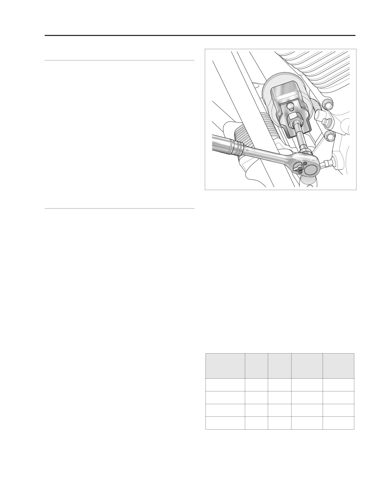
Figure 1-1. Remove Engine Oil Filter
ENGINE OIL/ENGINE OIL FILTER
6.
Clean the oil filter mount flange of any old gasket mate-
At the 1000 mile (1600 km) service interval, and at every
rial.
5000 mile (8000 km) service interval thereafter, change the
engine oil and engine oil filter as follows:
7.
Lubricate gasket with clean engine oil and install new oil
filter on filter mount. Hand tighten oil filter 1/2-3/4 turn
NOTE
after gasket first contacts filter mounting surface. Do
If the motorcycle is ridden hard, under dusty conditions, or in
NOT use OIL FILTER WRENCH for oil filter installation.
cold weather, the oil and filter should be changed more often.
NOTE
1. Ride vehicle until engine is at normal operating tempera-
ture.
Use of the Premium 10 micron synthetic media oil filter is
highly recommended, Part No. 63798-99 (Chrome) or 63731-
2. Locate oil filler plug/dipstick on right side of vehicle at top
99 (Black).
of transmission case. To remove the oil filler plug, pull
steadily while moving plug back and forth.
8. Install engine oil drain plug and tighten to 14-21 ft-lbs
3. Locate oil drain plug at front left side of the oil pan.
(19-28 Nm).
Remove the oil drain plug and allow oil to drain com-
9. With vehicle resting on jiffy stand, add 3-1/2 quarts (3.3
pletely.
liters) engine oil as specified in Table 1-1. Use the proper
4. Inspect the oil drain plug O-ring for cuts, tears or signs of
grade of oil for the lowest temperature expected before
deterioration. Replace as necessary.
the next oil change.
5. Remove the oil filter as follows:
Table 1-1. Recommended Engine Oils
a. Obtain the OIL FILTER WRENCH (HD-42311). The
tool allows easy removal of the oil filter without risk
Harley-
Lowest
Cold Weather
of damage to the crankshaft position sensor or
Harley-Davidson
Viscosity
Davidson
Ambient
Starts Below
cable.
Type
Rating
Temperature
50˚F (10˚C)
b. Place the jaws of the wrench over the oil filter with
SAE
Below 40˚F
the tool oriented vertically. See Figure 1-1.
HD Multi-grade
HD 360
Excellent
10W40
(4˚C)
c. Using a 3/8 inch drive with a 4 inch extension, turn
SAE
Above 40˚F
HD Multi-grade
HD 360
Good
wrench in a counterclockwise direction. Do not use
20W50
(4˚C)
with air tools.
SAE
Above 60˚F
HD Regular Heavy
HD 360
Poor
50
(16˚C)
NOTE
SAE
Above 80˚F
HD Extra Heavy
HD 360
Poor
Use OIL FILTER WRENCH (HD-44067) if HD-42311 is not
60
(27˚C)
available.
2004 Touring: Maintenance
1-15
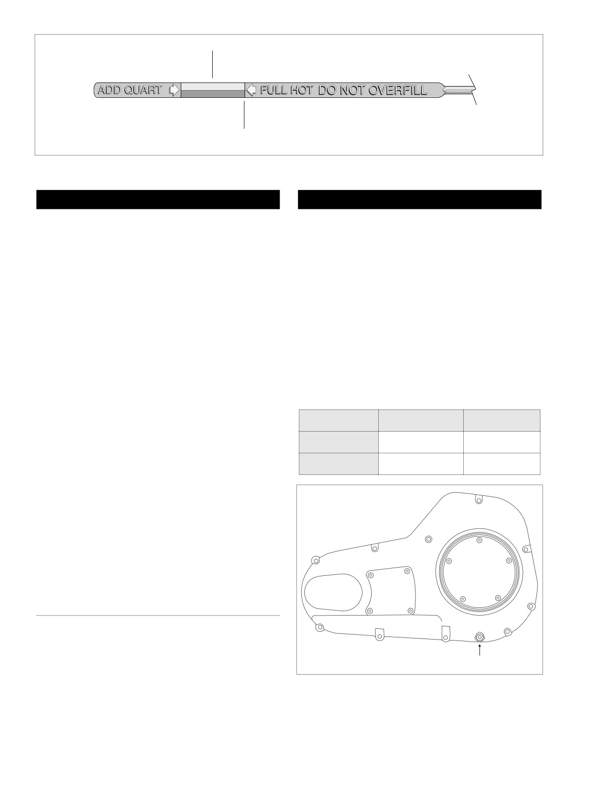
HOME
COLD CHECK
HOT CHECK
f1254b3x
Figure 1-2. Engine Oil Dipstick
CAUTION
1WARNING
Oil level cannot be accurately measured on a cold
To protect against shock and accidental start-up of vehi-
engine. For preride inspection, with motorcycle leaning
cle, disconnect the negative battery cable before pro-
on jiffy stand on level ground, oil should register on dip-
ceeding. Inadequate safety precautions could result in
stick between arrows when engine is cold. Do NOT add
death or serious injury.
oil to bring the level to the FULL mark on a COLD engine.
2.
Unthread bolt and remove battery negative cable (black)
10.
Perform engine oil level COLD CHECK as follows:
from battery negative (-) terminal.
a. With the vehicle resting on the jiffy stand on level
3.
See Figure 1-3. Using a T27 TORX drive head, remove
ground, wipe off the dipstick and insert it back into
four screws to free the primary chain inspection cover
the oil pan with the plug pushed completely into the
from the primary chaincase cover.
fill spout.
4.
Check the primary chain tension. Push on the upper
b. Remove the dipstick and note the level of the oil. Oil
strand to verify that it has free up and down movement
level should register between the two arrows on the
midway between the engine compensating sprocket
dipstick. See Figure 1-2. If oil level is at or below the
(front) and the clutch sprocket (rear).
lower arrow, add only enough oil to bring the level
between the two arrows on the dipstick.
Table 1-2. Primary Chain Adjustment
11.
Perform engine oil level HOT CHECK as follows:
a. Ride vehicle until engine is at normal operating tem-
(Free Play)
Inches
Millimeters
perature.
COLD ENGINE
5/8-7/8 inch
15.9-22.2 mm
b. With the vehicle resting on the jiffy stand on level
ground, allow engine to idle for 1-2 minutes. Turn
HOT ENGINE
3/8-5/8 inch
9.5-15.9 mm
engine off.
c. Wipe off the dipstick and insert it back into the oil
pan with the plug pushed completely into the fill
f1210x6x
spout.
d. Remove the dipstick and note the level of the oil.
Add only enough oil to bring the level to the FULL
mark on the dipstick. See Figure 1-2. Do not overfill.
1
12.
Start engine and carefully check for leaks around hoses,
1
4
Clutch
3
4
drain plug and oil filter.
Inspection
Primary
Cover
Chain
2
5
Inspection
Cover
PRIMARY CHAIN
2
3
At the 1000 mile (1600 km) service interval, and at every
5000 mile (8000 km) service interval thereafter, inspect the
primary chain tension and adjust if necessary.
Drain Plug
Proceed as follows:
1. Remove seat. See Section 2.24 SEAT, REMOVAL.
Figure 1-3. Primary Chaincase Cover
1-16
2004 Touring: Maintenance
HOME
PRIMARY CHAIN LUBRICANT
f1841x6x
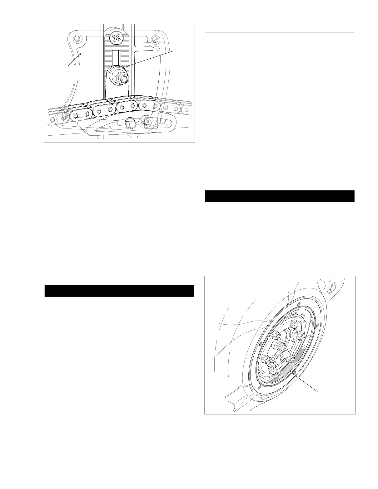
Top
At the 1000 mile (1600 km) service interval, and at every
Center
5000 mile (8000 km) service interval thereafter, replace the
Nut
primary chain lubricant as follows:
1.
Using a T27 TORX drive head, remove five screws (with
Chain Inspection
captive washers) to free clutch inspection cover from pri-
Cover Opening
mary chaincase cover.
2.
Remove magnetic drain plug at bottom of primary chain-
case cover. Drain lubricant into suitable container. See
Figure 1-3.
3.
Clean drain plug. If plug has accumulated a lot of debris,
inspect the condition of chaincase components.
4.
Inspect drain plug O-ring for cuts, tears or signs of dete-
rioration. Replace as necessary.
5.
Install drain plug back into primary chaincase cover.
Figure 1-4. Primary Chaincase Cover
Tighten plug to 36-60 in-lbs (4.1-6.8 Nm).
6.
Pour 32 ounces (946 ml) of Harley-Davidson PRIMARY
5. Measure the free play to be sure that it falls within the
CHAINCASE LUBRICANT through the clutch inspection
range specified for a hot or cold engine. See Table 1-2.
cover opening, Part No. 99887-84 (quart) or Part No.
99886-84 (gallon). See Figure 1-5.
6. If the chain is too tight or too loose, then adjust as fol-
lows:
CAUTION
a. Locate the chain tensioner assembly and loosen the
top center nut a maximum of two turns. See Figure
Do not overfill the primary chaincase with lubricant.
1-4.
Overfilling may cause rough clutch engagement, incom-
plete disengagement, clutch drag and/or difficulty in
b. Raise or lower the chain tensioner assembly as
finding neutral at engine idle.
necessary to obtain the specified free play.
7. Remove quad ring from groove in primary chaincase
NOTE
cover. Wipe all lubricant from the quad ring and inspect
As chains stretch and wear, they run tighter at one spot than
for cuts, tears or signs of deterioration. Replace as nec-
essary.
another. Always adjust the free play at the tightest spot in the
chain. Replace the primary chain if it is worn to the point
where it cannot be properly adjusted.
Primary
Chaincase Cover
CAUTION
Always keep the primary chain properly adjusted. Allow-
ing the chain to run too tight or too loose will result in
excessive chain and sprocket wear.
c. Tighten the top center nut of the chain tensioner
assembly to 21-29 ft-lbs (29-39 Nm).
7. Align holes in new gasket with holes in the primary
chaincase cover. Using a T27 TORX drive head, install
four screws to secure primary chain inspection cover to
primary chaincase cover. Alternately tighten screws to
84-108 in-lbs (10-12 Nm) in a crosswise pattern. See
Figure 1-3.
8. Insert bolt through battery negative cable (black) into
Lubricant
threaded hole of battery negative (-) terminal. Tighten
bolt to 60-96 in-lbs (6.8-10.9 Nm).
f1508b6x
9. Install seat. See Section 2.24 SEAT, INSTALLATION.
Figure 1-5. Fill Primary Chaincase With Lubricant
2004 Touring: Maintenance
1-17
HOME
CLUTCH ADJUSTMENT
f1440x6x
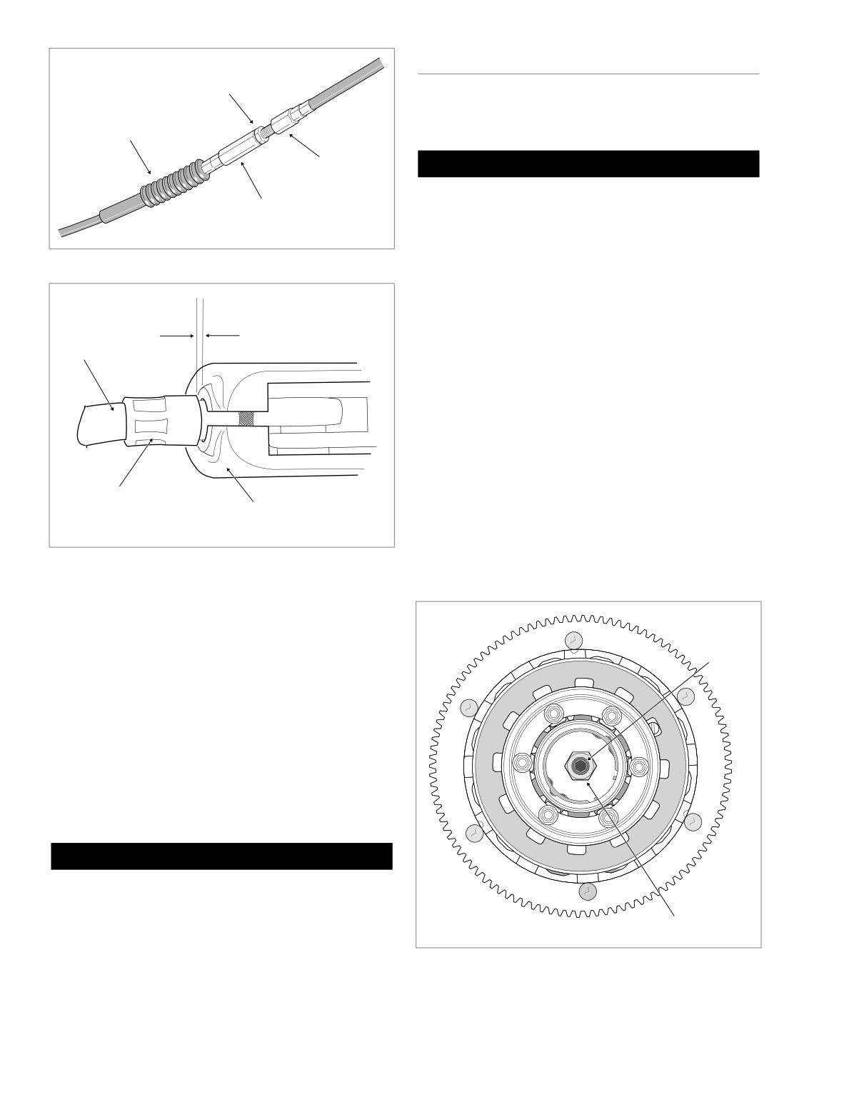
Jam
Nut
At the 1000 mile (1600 km) service interval, and at every
5000 mile (8000 km) service interval thereafter, adjust the
Rubber
clutch as follows:
Boot
Cable
CAUTION
End
Perform the clutch adjustment with the motorcycle at
Cable
room temperature. The clearance at the adjuster screw
Adjuster
will increase as the powertrain temperature increases. If
adjuster screw is adjusted while the powertrain is hot,
clearance at push rod bearing could be insufficient with
Figure 1-6. Clutch Cable Adjuster Mechanism
powertrain cold and clutch slippage could occur.
NOTE
Adjust for 1/16-1/8 inch
(1.6-3.2 mm) gap
Perform adjustment procedure whenever clutch components
between ferrule
are replaced during normal servicing. Repeat adjustment
Clutch
and bracket
after 500 miles (800 km) of use.
Cable
1.
Stand vehicle upright and level.
2.
Using a T27 TORX drive head, remove five screws (with
captive washers) to free clutch inspection cover from pri-
mary chaincase cover.
3.
See Figure 1-6. Slide rubber boot off cable adjuster.
Holding cable adjuster with 1/2 inch wrench, loosen jam
nut using a 9/16 inch wrench. Back jam nut away from
Ferrule
cable adjuster. Move adjuster toward jam nut to intro-
Clutch Lever
duce a large amount of free play at hand lever.
f1421x6x
Bracket
4.
See Figure 1-8. Loosen locknut on clutch adjuster screw.
To take up all free play in push rods, turn screw inward
Figure 1-7. Adjust Clutch Free Play
(clockwise) until lightly seated.
8.
Swab all lubricant from the quad ring groove. Install
quad ring in primary chaincase cover with the nubs con-
f1509b6x
Clutch
tacting the ring groove walls.
Adjuster
NOTE
Screw
If lubricant is not thoroughly removed from both the quad ring
and groove, compression of the ring during installation of the
clutch inspection cover can cause lubricant to be squeezed
to the outboard side of the ring groove, resulting in some
temporary weepage around the inspection cover.
9.
Using a T27 TORX drive head, install five screws (with
captive washers) to secure clutch inspection cover to the
primary chaincase cover. Alternately tighten screws to
84-108 in-lbs (10-12 Nm) in the pattern shown in Figure
1-3.
1WARNING
When adding lubricant, do not allow dirt, debris or other
contaminants to enter the primary chaincase. Exercise
caution so that lubricant does not contact rear wheel,
Locknut
tire and brake components. Such contact can adversely
affect traction and may lead to loss of vehicle control,
which could result in death or serious injury.
Figure 1-8. Clutch Assembly
1-18
2004 Touring: Maintenance
HOME
5.
Back out adjuster screw 1/2 to 1 turn. While holding
adjuster screw with an allen wrench, tighten locknut to
8496
Clutch
72-120 in-lbs (8-14 Nm).
Release
Cover
6.
Squeeze clutch lever to maximum limit three times to set
ball and ramp release mechanism.
7.
Turn cable adjuster away from jam nut until slack is elim-
inated at hand lever. Pull clutch cable ferrule away from
clutch lever bracket to check free play. Turn cable
adjuster as necessary to obtain 1/16 to 1/8 inch (1.6 -
3.2 mm) free play between end of cable ferrule and
clutch lever bracket, as shown in Figure 1-7.
Filler
8.
Hold adjuster with 1/2 inch wrench. Using 9/16 inch
Plug
wrench, tighten jam nut against cable adjuster. Cover
cable adjuster mechanism with rubber boot.
9.
Remove quad ring from groove in primary chaincase
cover. Wipe all lubricant from the quad ring and inspect
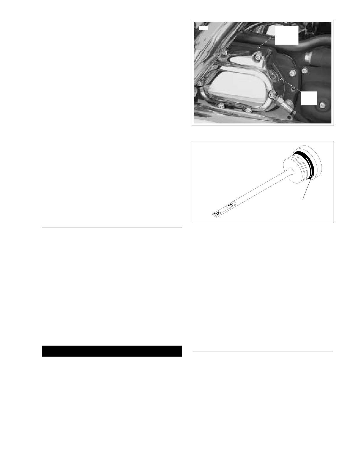
Figure 1-9. Transmission Case (Right Side)
for cuts, tears or signs of deterioration. Replace as nec-
essary.
OMF50
10.
Swab all lubricant from the quad ring groove. Install
quad ring in primary chaincase cover with the nubs con-
tacting the ring groove walls.
11.
Using a T27 TORX drive head, install five screws (with
captive washers) to secure clutch inspection cover to the
primary chaincase cover. Alternately tighten screws to
84-108 in-lbs (10-12 Nm) in the pattern shown in Figure
1-3.
O-Ring
TRANSMISSION LUBRICANT
Figure 1-10. Transmission Lubricant Filler Plug/Dipstick
At the 1000 mile (1600 km) service interval, and at every
5000 mile (8000 km) service interval thereafter, replace the
transmission lubricant as follows:
5.
Fill the transmission with
20-24 oz. (590-710 ml) of
transmission lubricant or until the lubricant level on the
1. Remove the filler plug from the clutch release cover on
dipstick of the filler plug is at the F(ULL) mark with the
the right side of the transmission case. See Figure 1-9.
motorcycle in a level, upright position and the filler plug
Check the O-ring for tears, cuts or general deterioration.
resting on the threads.
Replace as necessary. See Figure 1-10.
Use only Harley-Davidson SEMI-SYNTHETIC TRANS-
2. Locate transmission drain plug on the right side of the oil
MISSION LUBRICANT: Part No.’s 99892-84 (quart),
pan. Remove the magnetic plug and drain the transmis-
98853-96 (case of quarts), 99891-84 (gallon), or 98852-
sion lubricant into a suitable container.
96 (case of gallons).
3. Remove any foreign material from the drain plug. Check
6.
Install the transmission filler plug/dipstick in the clutch
the O-ring on the drain plug for tears, cuts or general
release cover. Tighten the plug to 25-75 in-lbs (2.8-8.5
deterioration. Replace as necessary.
Nm).
4. Install the transmission lubricant drain plug and tighten
to 14-21 ft-lbs (19-28 Nm).
TIRES
1WARNING
At the 1000 mile (1600 km) service interval, and at every
When adding lubricant, do not allow dirt, debris or other
5000 mile (8000 km) service interval thereafter, inspect both
contaminants to enter the transmission case. Exercise
the tire condition and pressure.
caution so that lubricant does not contact rear wheel,
1.
Inspect for wear as follows:
tire and brake components. Such contact can adversely
affect traction and may lead to loss of vehicle control,
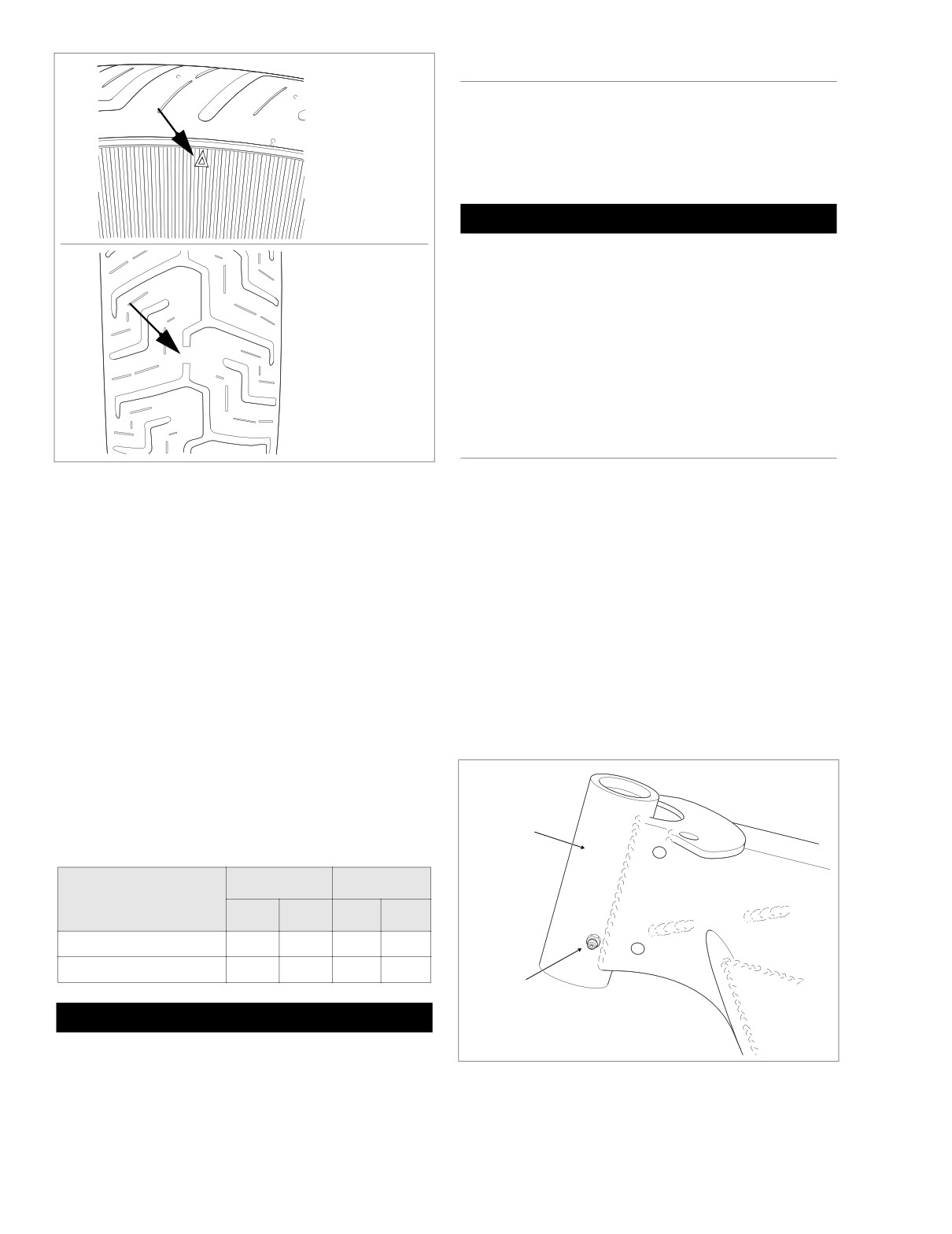
a. Locate the arrows on the tire sidewalls. The arrows
which could result in death or serious injury.
point to location of the tread wear indicator bars.
See upper frame of Figure 1-11.
2004 Touring: Maintenance
1-19
HOME
WHEEL SPOKES
o0250xox
At the 1000 mile (1600 km) service interval, the 5000 mile
(8000 km) service interval, and then every
15,000 mile
Sidewall
(24,000 km) service interval thereafter, inspect spoke tight-
Arrow
ness, if applicable. Proceed as follows:
1.
Raise wheel off the ground.
CAUTION
If nipples require more than one full turn to tighten
spoke, remove tire to check that spoke protrusion has
not damaged tube.
2.
Lightly tap each spoke with a spoke wrench. Loose
spokes will sound dull and must be tightened. Tighten
Indicator Bar on
spokes to 40-50 in-lbs (4.5-5.6 Nm). If more than a few
Tread Surface
spokes are loose, true the entire wheel following the pro-
cedure under Section 2.7 TRUING LACED WHEEL.
o0249xox
STEERING HEAD BEARINGS
Figure 1-11. Tread Wear Indicator Bars
At the 1000 mile (1600 km) service interval, and at every
10,000 mile (16,000 km) service interval thereafter, grease
the steering head bearings using Special Purpose Grease,
b. Immediately replace tires if any tread wear indicator
Part No. 99857-97. Turn handlebar full right to access the
bar is on the tire tread surface, indicating that 1/32
grease fitting at the left side of the steering head. Connect
inch (0.8 mm) or less of tire tread pattern remains.
grease gun to fitting and inject grease until it exudes from top
See lower frame of Figure 1-11.
and bottom of steering head. See Figure 1-12.
NOTE
At every 25,000 mile (40,000 km) service interval, check the
Harley-Davidson recommends that the tires be replaced
swing-by following the procedure under Section
2.17
BEFORE the tread wear indicator bars are on the tire tread
STEERING HEAD BEARINGS and adjust as necessary.
surface.
At every 50,000 mile (80,000 km) service interval, disassem-
2.
Inspect for damage. Replace tires if:
ble the steering head and inspect the bearings for brinelling,
● Cords or fabric become visible through cracked
scoring, or other damage. Replace and/or repack the bear-
ings as required. See Section 2 for more information.
sidewalls, snags or deep cuts.
● Bump, bulge or split line is observed.
● Puncture, deep cut or other damage is present that
is not repairable.
f2108x2x
3. Check tire pressure.
Steering
Head
Table 1-3. Tire Pressure (Cold)
FRONT
REAR
DUNLOP TIRES ONLY
PSI
BARS
PSI
BARS
Solo Rider
36
2.5
36
2.5
Rider & One Passenger
36
2.5
40
2.8
Grease
Fitting
1WARNING
Do not inflate tires beyond the maximum inflation pres-
sure specified on tire sidewall. Overinflation can lead to
Figure 1-12. Steering Head Bearing Grease Fitting
tire failure while vehicle is in operation, which could
result in death or serious injury.
1-20
2004 Touring: Maintenance
HOME
BRAKE FLUID
DRIVE BELT
At the 1000 mile (1600 km) service interval, and at every
At the 1000 mile (1600 km) service interval, and at every
5000 mile (8000 km) service interval thereafter, inspect the
5000 mile (8000 km) service interval thereafter, inspect drive
brake fluid condition and level. Proceed as follows:
belt for damage and proper deflection. Proceed as follows:
1.
Remove left side saddlebag. See Section 2.25 SAD-
CAUTION
DLEBAG, REMOVAL.
To prevent dirt from entering the master cylinder reser-
2.
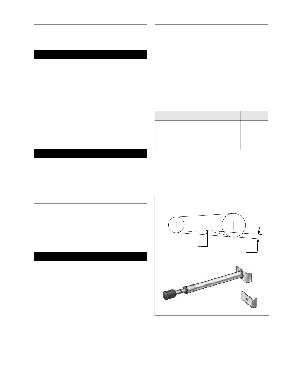
Check deflection at the loosest spot in the belt with the
voir, thoroughly clean the cover before removal.
transmission in neutral and the motorcycle cold. Use
BELT TENSION GAUGE (HD-35381A), or install narrow
1. Remove two Phillips screws from cover of master cylin-
saddle (HD-35381-3) on existing gauge, and apply 10
der reservoir. Remove cover (with gasket).
lbs. (4.5 kg) of force at the midpoint of the bottom belt
2. Stand the vehicle upright so that the master cylinder res-
strand. See Figure 1-13. Belt deflection should be as fol-
ervoir is in a level position. Fluid level should be 1/ 8 inch
lows:
(3.2 mm) from the top. Add fluid as necessary.
Table 1-4. Belt Deflection
NOTE
Use only D.O.T. 5 SILICONE HYDRAULIC BRAKE FLUID,
Orientation
Inches
Millimeters
Part No. 99902-77 (12 oz.) or Part No. 99901-77 (gallon).
On Jiffy Stand
Without Rider or Luggage
1/4 - 5/16
6.4
- 7.9
3. Install cover (with gasket) on the master cylinder reser-
10 psi (69 kPa) in Rear Shocks
voir. Install two Phillips screws and tighten to 6-8 in-lbs
(0.7-0.9 Nm).
Motorcycle Upright
3/16 - 1/4
4.8
- 6.4
With Rear Wheel in the Air
1WARNING
If belt deflection is within specification, install left side
Whenever the brake system is serviced, it should be
saddlebag. If adjustment is necessary, move to step 3.
tested on dry, clean pavement at slow speeds before put-
ting the motorcycle into regular service. Improperly ser-
3.
Remove right side saddlebag. See Section 2.25 SAD-
viced brakes can lead to an accident that could result in
DLEBAG, REMOVAL.
death or serious injury.
4.
Remove right side muffler as follows:
BRAKE PADS AND DISCS
Transmission
Rear Wheel
Sprocket
Sprocket
At the 1000 mile (1600 km) service interval, and at every
5000 mile (8000 km) service interval thereafter, inspect the
brake pads and discs as follows:
Brake Pads
If brake pad friction material is worn to 0.04 inch (1.02 mm) or
less, replace the entire set of pads.
10 lbs. (4.5 kg)
of Force
f1652x6x
See Table 1-4.
1WARNING
For correct and safe brake operation, brake pads must
Belt Tension Gauge
be replaced in sets at the same time. Mismatched brake
Part No. HD-35381A
pads could lead to an accident resulting in death or seri-
ous injury.
Brake Discs
The minimum brake disc thickness is stamped on the side of
the disc.
Belt Tension Gauge Adapter
Part No. HD-35381-3
When checking the brake pads and discs, inspect the brake
lines and hoses for damage or leaks.
Figure 1-13. Check and Adjust Belt Deflection
2004 Touring: Maintenance
1-21
HOME
LEFT SIDE
RIGHT SIDE
Increase
Reduce
Belt
Belt
Deflection
Deflection
Cone
Nut
Weld
Nub
Weld
Weld
Nut
E-Clip
Nub
Adjuster
Cam
8398
8407
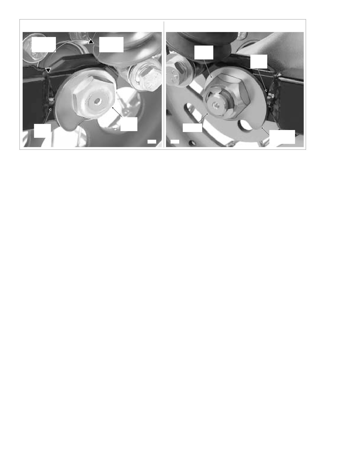
Figure 1-14. Move Rear Wheel Forward Until Adjuster Cams Just Contact Weld Nubs
a. Open worm drive clamps to remove heat shield
c. Push wheel forward slightly so that adjuster cam
from rear header pipe in front of muffler.
just contacts weld nub on both sides of rear swing-
arm. See Figure 1-14.
b. Using a bungee cord, tie the muffler to the lower
saddlebag support rail.
d. Check belt deflection. Apply 10 lbs. (4.5 kg) of force
at the midpoint of the bottom belt strand. Belt
c. Loosen TORCA clamp between rear header pipe
deflection should be within the range specified in
and muffer.
Table 1-4.
d. Remove two bolts (with lockwashers) to detach muf-
e. If belt is still too tight, repeat steps 7(b) through 7(d).
fler from the lower saddlebag support rail.
If belt is now too loose, move to step 6.
e. Remove bungee cord to release muffler from lower
saddlebag support rail.
8. Holding weld nut on left side of axle, tighten cone nut on
right side to 95-105 ft-lbs (128.8-142.4 Nm).
5.
Standing on right side of vehicle, remove E-clip from
NOTE
groove at end of axle. Loosen cone nut, and then snug
If the axle moves during tightening of the cone nut, then the
to 15-20 ft-lbs (20-27 Nm). See Figure 1-14.
the belt deflection procedure must be restarted.
6.
If belt is too tight, move to step 7 to increase belt deflec-
tion. If belt is too loose, reduce belt deflection as
9. Recheck belt deflection to verify that it is still within spec-
ification.
described below:
a. Rotate weld nut on left side of axle in a clockwise
If the belt deflection is not within specification, loosen
cone nut and then snug to 15-20 ft-lbs (20-27 Nm)
direction.
before returning to step 6.
b. Check belt deflection. Apply 10 lbs. (4.5 kg) of force
10. With the flat side out, install new E-clip in groove on right
at the midpoint of the bottom belt strand. Belt
side of axle.
deflection should be within the range specified in
Table 1-4.
11. Install right side muffler as follows:
c. If belt is still too loose, repeat steps 6(a) through
NOTE
6(b). If belt is now too tight, move to step 7.
TORCA muffler clamps have eliminated the need for silicone
or graphite tape during assembly. To ensure sealing integrity
7.
If belt is too tight, increase belt deflection as follows:
of muffler clamps and prevent the possibility of leakage, Har-
a. Using a hydraulic center stand, raise motorcycle so
ley-Davidson recommends that TORCA clamp assemblies be
that the rear wheel is off the ground.
discarded and replaced each time they are removed.
b. Rotate weld nut on left side of axle in a counter-
a. Slide new TORCA clamp onto free end of rear
clockwise direction.
header pipe.
1-22
2004 Touring: Maintenance
HOME
b. Using a bungee cord, tie muffler to lower saddlebag
REAR SHOCK ABSORBERS
support rail. Install muffler on rear header pipe.
Place TORCA clamp into position between rear
At the 1000 mile (1600 km) service interval, and at every
header pipe and muffler.
5000 mile (8000 km) service interval thereafter, inspect the
c. Tighten the two bolts (with lockwashers) to fasten
rear shock absorbers for signs of leakage or damage, and
the muffler to the lower saddlebag support rail.
replace if necessary. For adjustment of rear air suspension
pressures, see Section 2.18 REAR AIR SUSPENSION.
CAUTION
Verify that the exhaust pipes do not contact the vehicle
AIR CLEANER
frame or any mounted components. Contact will cancel
the effect of the rubber isolation mounts and transmit
At the 1000 mile (1600 km) service interval, and at every
vibration to the rider via the vehicle frame.
5000 mile (8000 km) service interval thereafter, inspect the
air cleaner filter element, and clean or replace as necessary.
d. Verify that exhaust pipes are in alignment and do
not contact the vehicle frame or mounted compo-
1.
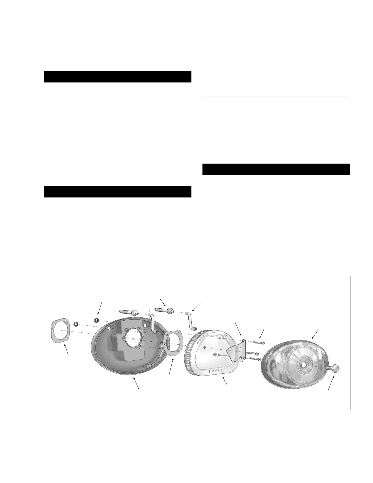
Remove large allen head socket screw in center of air
nents.
cleaner cover. Remove air cleaner cover with rubber
seal. See Figure 1-15.
e. Tighten the TORCA clamp to 45-60 ft-lbs (61-81
2.
Remove three T27 TORX screws to release cover
Nm).
bracket from filter element.
f.
Open worm drive clamps and install heat shield on
rear header pipe. Position clamp so that screw is on
CAUTION
the outboard side in the most accessible position.
Never run the engine with the filter element removed.
The filter prevents dirt and dust from entering the
CAUTION
engine.
Verify that the heat shields do not contact the vehicle
3.
Remove filter element pulling two breather tubes from
frame or any mounted components. Contact will cancel
holes on inboard side.
the effect of the rubber isolation mounts and transmit
4.
Remove gasket from sleeve on inboard side of filter ele-
vibration to the rider via the vehicle frame.
ment. Discard gasket.
g. Remove bungee cord from muffler.
5.
Remove breather tubes from fittings on two cylinder
head breather bolts.
12. Install saddlebags. See Section
2.25 SADDLEBAG,
6.
Remove two cylinder head breather bolts from backplate
INSTALLATION.
using a 7/16 inch deepwell socket.
f1650x4x
Cylinder Head
Breather
Breather Bolt
O-Ring
Tube
Cover
Bracket
T27 Torx
Air Cleaner
Screw
Cover
Gasket
Gasket
Filter
Backplate
Element
Cover Screw
Figure 1-15. Air Cleaner Assembly
2004 Touring: Maintenance
1-23
HOME
7.
Remove backplate from cylinder heads. On carbureted
21. Insert breather tubes about 1/4 inch (6.4 mm) into holes
California models, pull clean air inlet tube (to charcoal
on inboard side of filter element.
canister) from hole on inboard side of backplate.
22. Install breather tubes onto fittings of two cylinder head
8.
Remove two O-rings from grooves around breather bolt
breather bolts.
holes on inboard side of backplate. Discard O-rings.
NOTE
9.
Remove gasket from inboard side of backplate. Discard
Air cleaner mounting without installation of the breather
gasket.
tubes allows crankcase vapors to be vented into the atmo-
sphere in violation of legal emissions standards.
10. Thoroughly clean air cleaner cover and backplate.
11. Replace the filter element if damaged or if filter media
23. Place filter element onto backplate with the flat side
cannot be adequately cleaned.
down, so that hole on inboard side of element fits over
molded boss in backplate.
12. Wash the filter element and breather tubes in warm,
24. Align holes in cover bracket with those in filter element
soapy water. To remove soot and carbon, soak element
for 30 minutes in warm water with mild detergent.
and start three T27 TORX screws. Stamp on cover
bracket points to downside. Alternately tighten screws to
20-40 in-lbs (2.3-4.5 Nm) in a crosswise pattern.
1WARNING
25. Verify that rubber seal is properly seated around perime-
Do not use gasoline or solvents to clean the filter ele-
ter of air cleaner cover. Replace seal if cut, torn or shows
ment. Volatile or flammable cleaning agents may cause
signs of deterioration.
an intake system fire, which could result in death or seri-
26. Fit air cleaner cover into backplate. Apply a small dab of
ous injury.
Loctite Medium Strength Threadlocker
243 (blue) to
threads of large allen head socket screw. Install screw in
center of air cleaner cover. Tighten screw to 36-60 in-lbs
1WARNING
(4.1-6.8 Nm).
Compressed air can pierce the skin and cause injury.
Never use your hand to check for leaks or to determine
air flow rates. Wear safety glasses to shield your eyes
FUEL SYSTEM LINES
from flying dirt and debris. Failure to comply could result
in death or serious injury.
AND FITTINGS
13.
Dry the filter element using low pressure compressed air
At the 1000 mile (1600 km) service interval, and at every
(32 psi/221 kPa maximum). Rotate the element while
5000 mile (8000 km) service interval thereafter, inspect the
moving air nozzle up and down the element interior. Do
fuel system lines and fittings for leaks or damage.
not rap the element on a hard surface.
14.
Hold the filter element up to a strong light source. The
element can be considered sufficiently clean if light is
FUEL TANK FILTER (CARBURETED)
uniformly visible through the media.
15.
Inspect the breather tubes for cuts, tears, holes or signs
At every 25,000 mile (40,000 km) service interval, remove
of deterioration. Replace as necessary. Direct com-
and inspect the fuel tank filter as follows:
pressed air through the breather tubes to verify that they
are not plugged.
1
WARNING
16.
Install new O-rings in grooves around breather bolt
holes on inboard side of backplate.
Gasoline is extremely flammable and highly explosive.
When servicing the fuel system, do not smoke or allow
17.
Aligning flat edge of gasket with molded tab, install new
open flame or sparks in the vicinity. Inadequate safety
gasket on inboard side of backplate. On California mod-
precautions could result in death or serious injury.
els, install gasket by aligning small holes with plastic
pins.
1.
Turn the handle of the fuel valve to OFF.
18.
On California models, push clean air inlet tube (to char-
coal canister) into hole on inboard side of backplate.
1WARNING
19.
Align holes in backplate with those in cylinder heads and
A small amount of gasoline may drain from the carbure-
install cylinder head breather bolts. Using a 7/16 inch
tor fuel inlet hose when disconnected from the fuel valve
deepwell socket, alternately tighten bolts to 10-12 ft-lbs
fitting. Thoroughly wipe up any spilled fuel immediately
(13.6-16.3 Nm).
and dispose of rags in a suitable manner. Gasoline is
20.
Slide new gasket over sleeve on inboard side of filter
extremely flammable and highly explosive. Inadequate
element. Be sure holes in gasket are aligned with those
safety precautions could result in death or serious
in filter.
injury.
1-24
2004 Touring: Maintenance
HOME
8.
When the fuel tank is completely drained, remove the
f1960x4x
Mity-Vac® Hand Pump from the vacuum fitting.
Filter
9.
Holding fuel tank adapter, turn the hex jam nut in a
Strainer
clockwise direction to remove the fuel valve assembly.
10.
Remove the fuel filter strainer from the valve head.
Clean or replace.
11.
Remove the hex jam nut from the fuel valve.
12.
Remove the gasket from the valve head. Discard the
gasket.
Carburetor
13.
Install a new gasket on the valve head.
Fuel Inlet
Hose
14.
Install the fuel filter strainer fitting the internal tube into
Jam
the larger hole in the valve head.
Nut
15.
Apply Loctite Pipe Sealant with Teflon 565 to threads of
Vacuum
fuel valve and fuel tank adapter.
Fitting
Gasket
16.
With the hex side down, turn the jam nut two full turns in
a counterclockwise direction to thread onto fuel tank
adapter.
17.
Insert fuel filter strainer into fuel tank. Holding the hex
jam nut to prevent rotation, turn the fuel valve two full
Hose
turns in a clockwise direction to thread onto hex jam nut.
Clamp
Convoluted
Tubing
1WARNING
Fuel
Outlet
Do not thread fuel valve onto hex jam nut more than two
Fitting
turns or nut may “bottom” on valve, a condition which
Atmospheric
Valve
Pressure
may result in a gasoline leak. Any gasoline leak is a
Handle
Port
potential fire hazard that could result in death or serious
injury.
Figure 1-16. Vacuum Operated Fuel Valve
18. Holding the fuel valve to prevent rotation, turn the hex
jam nut in a counterclockwise direction until snug.
Tighten the hex jam nut to 15-20 ft-lbs (20.3-27.1 Nm).
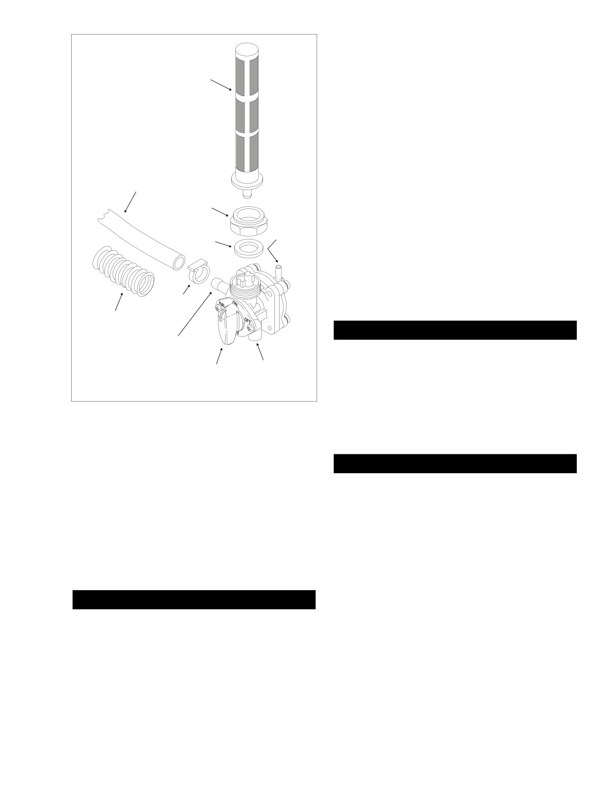
2.
Using a side cutters, cut clamp and remove hose from
fuel outlet fitting at the front of the fuel valve. See Figure
1-16. Drain free end of hose into a suitable container.
CAUTION
3.
Remove elbow of intake manifold vacuum tube from fit-
Do not allow dirt or fluids to get into the vacuum tube
ting on inboard side of the fuel valve.
that connects the fuel valve to the intake manifold. Con-
4.
Attach a length of fuel hose to the fuel outlet fitting. The
taminants can block the vacuum signal which could
hose must be long enough to reach a suitable gasoline
cause the fuel valve to malfunction.
container.
19. Connect elbow of intake manifold vacuum tube to fitting
5.
Turn the handle of the fuel valve to RES(ERVE).
on inboard side of the fuel valve.
6.
Using the correct hose adapter, connect the Mity-Vac®
20. Slide new clamp onto free end of carburetor fuel inlet
Hand Pump (HD-23738A) to the vacuum fitting.
hose. Install hose onto fuel outlet fitting at front of fuel
valve. Crimp clamp using HOSE CLAMP PLIERS (HD-
97087-65B).
CAUTION
21. Turn the handle of the fuel valve to OFF and fill the fuel
To avoid damage to the diaphragm of the fuel valve, do
tank. Carefully inspect for leaks at fitting.
not apply a vacuum greater than 25 inches of Mercury
(Hg) to the vacuum fitting.
22. Turn the valve handle to ON and start engine. No prim-
ing or special procedures are required to start fuel flow.
7. Gently apply a vacuum of 1-10 inches of Mercury (Hg) to
Carefully inspect for leaks at fitting.
the vacuum fitting to get a good flow of gasoline through
the valve.
23. Stop engine and return the valve to the OFF position.
2004 Touring: Maintenance
1-25
HOME
f1438x4x
Mounting
f1225x2x
Lockwasher
Bracket
Enrichener
Knob
Hex
Nut
Knurled
Enrichener
Nut
Flat
Cable
5/32 Inch
(4.0 mm)
Figure 1-17. Enrichener Control
Cardboard
Insert
ENRICHENER CONTROL
At the 1000 mile (1600 km) service interval, and at every
Figure 1-18. Install Cardboard Insert
5000 mile (8000 km) service interval thereafter, inspect the
enrichener control as follows:
Notch
Ferrule
The fuel enrichener knob should open, remain open and then
close without binding. The knurled plastic nut next to the
enrichener knob controls the ease at which the cable slides
within the conduit.
Groove
If adjustment is needed, proceed as follows:
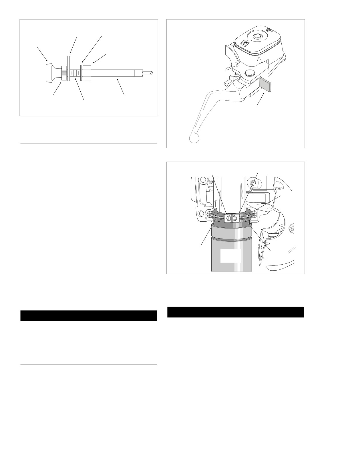
1. See Figure 1-17. Loosen hex nut at backside of mount-
ing bracket.
2. Move cable assembly free of slot in mounting bracket.
3. Hold cable assembly at flat with adjustable wrench.
Hand turn knurled nut counterclockwise to reduce sliding
Idle
resistance until knob slides inward unaided.
Cable
Throttle
Throttle
4. Turn knurled nut clockwise to increase sliding resistance
Grip
Cable
until knob remains fully out without holding and then
f1474x2x
closes with relative ease.
Figure 1-19. Remove Throttle/Idle Cables
5. Slide enrichener cable into slot of mounting bracket.
With external tooth lockwasher and hex nut positioned
on the inboard side of the mounting bracket, tighten hex
Lubrication
nut to 20-35 in-lbs (2.3-4.0 Nm).
CAUTION
CAUTION
Do not remove the switch housing assembly without first
Do not lubricate the cable or inside of conduit. The cable
placing the 5/32 inch (4.0 mm) cardboard insert between
must have sliding resistance to work properly.
the brake lever and lever bracket. Removal without the
insert may result in damage to the rubber boot and
plunger of the Front Stoplight Switch.
THROTTLE CABLES
NOTE
Use the eyelet of an ordinary cable strap if the cardboard
insert is not available.
At the 1000 mile (1600 km) service interval, and at every
5000 mile (8000 km) service interval thereafter, inspect and
1.
Place the cardboard insert between the brake lever and
lubricate the throttle and clutch cables as follows:
lever bracket. See Figure 1-18.
1-26
2004 Touring: Maintenance
HOME
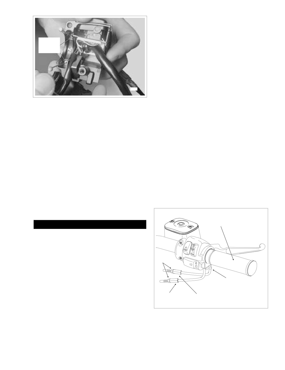
9.
Apply a light coating of graphite to the handlebar.
10.
Slide the throttle control grip over the end of the right
handlebar until it bottoms against the closed end. Rotate
the grip so that the ferrule notches are at the top. To pre-
Insert
vent binding, pull the grip back about 1/8 inch (3.2 mm).
Lubricant
11.
Position the lower switch housing beneath the throttle
Here
control grip. Install the brass ferrules onto the cables so
that the end fittings seat in the ferrule recess. Seat the
ferrules in their respective notches on the throttle control
grip. Verify that the cables are captured in the grooves
molded into the grip. See Figure 1-19.
12.
Position the upper switch housing over the handlebar
and lower switch housing. Verify that the wire harness
7958
conduit runs in the depression at the bottom of the han-
dlebar.
Figure 1-20. Lubricate Throttle/Idle Cables
13.
Start the upper and lower switch housing screws, but do
not tighten.
2. Using a T25 TORX drive head, remove the upper and
14.
Position the brake lever/master cylinder assembly
lower switch housing screws.
inboard of the switch housing assembly engaging the
tab on the lower switch housing in the groove at the top
3. Using a T27 TORX drive head, loosen the upper screw
of the brake lever bracket.
securing the handlebar clamp to the master cylinder
housing. Remove the lower clamp screw with flat
15.
Align the holes in the handlebar clamp with those in the
washer.
master cylinder housing and start the lower screw (with
4. Remove the brass ferrules from the notches on the
flat washer). Position for rider comfort. Beginning with
inboard side of the throttle control grip. Remove the fer-
the top screw, tighten the screws to 60-80 in-lbs (6.8-9.0
rules from the cable end fittings. See Figure 1-19.
Nm) torque using a T27 TORX drive head.
16.
Using a T25 TORX drive head, tighten the lower and
NOTE
upper switch housing screws to 35-45 in-lbs (4-5 Nm).
On non cruise equipped models, remove the friction shoe
from the end of the tension adjuster screw. The friction shoe
NOTE
is a loose fit and may fall out or become dislodged if the lower
Always tighten the lower switch housing screw first so that
switch housing is turned upside down or shaken.
any gap between the upper and lower housings is at the front
5. Remove the throttle control grip from the end of the han-
of the switch assembly.
dlebar.
6. Move upper switch housing to the side in order to access
lower housing.
f1376b2x
Throttle Control
Grip
1CAUTION
Lubit-8 Tufoil Chain and Cable Lube contains detergents.
Avoid contact with eyes. Keep out of reach of children.
7. Obtain tube of Lubit-8 Tufoil Chain and Cable Lube (HD
Part No. 94968-85TV- 1/4 fl. oz.). Insert pin of tube
between throttle cable and cable housing inside lower
Jam Nut
switch housing. Squeeze tube to squirt a quantity of
lubricant into cable housing moving pin around cable
OD. See Figure 1-20.
8. Repeat the procedure squirting a quantity of lubricant
Tension
between the idle cable and cable housing.
Adjuster
Screw
NOTE
Idle Cable
Throttle Cable
On non cruise equipped models, install the friction shoe with
Adjuster
Adjuster
the concave side up so that the pin hole is over the point of
the adjuster screw. The friction shoe is a loose fit and may fall
out or become dislodged if the lower switch housing is turned
Figure 1-21. Throttle Cable Assembly - Throttle Side
upside down or shaken.
(FLHR/S)
2004 Touring: Maintenance
1-27
HOME
Idle
Throttle
Cable Guide
Cable Guide
Cable
Housing
Spring
Cable
Barrel End
Throttle
Stop Plate
Throttle
Wheel
Cam Stop
f1381a2x
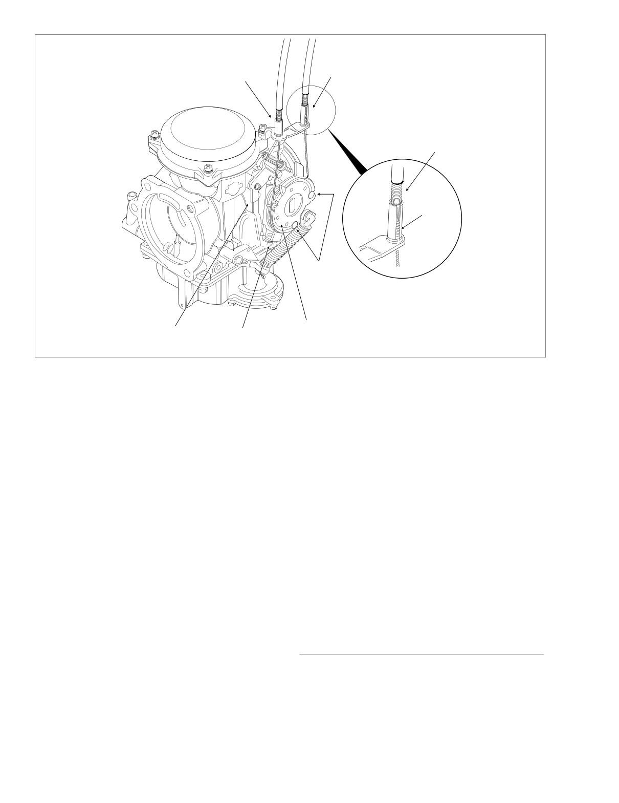
Figure 1-22. Throttle Cable Assembly - Carburetor Side
17. Remove the cardboard insert between the brake lever
3.
Turn the front wheel full right. Turn the idle cable adjuster
and lever bracket.
counterclockwise until the cable housing just touches
the spring in the longer cable guide. Work the throttle
18. Turn the Ignition/Light Key Switch to IGNITION and
grip to verify that the throttle cable returns to the idle
apply brake lever to test operation of brake lamp.
position when released. If the cable does not return to
idle, turn the adjuster clockwise slightly until the correct
Adjustment
response is achieved. Tighten jam nut against the idle
cable adjuster and cover cable adjuster mechanism with
NOTE
rubber boot.
For throttle and idle cable adjustment on cruise equipped
models, see Section
8.30 CRUISE CONTROL (FLHRC,
4.
Verify that the throttle control operates freely without
FLTR, FLHTCU).
binding. With the tension adjuster screw backed off, the
throttle control grip must freely return to the closed (idle)
1. Slide rubber boot off throttle cable adjuster. See Figure
position. The throttle control also must open and close
1-21. Holding cable adjuster with a 3/8 inch wrench,
freely when the front wheel is turned to both the right
loosen jam nut turning in a clockwise direction. Back jam
and left fork stops.
nut away from cable adjuster until it stops. Turn adjuster
If the throttle grip does not return to the idle position
clockwise until it contacts jam nut. Repeat procedure on
freely, check the adjuster screw tension. If the adjuster
idle cable adjuster.
screw is backed off, inspect the cables for short bends.
2. Point the front wheel straight ahead. Turn the throttle
control grip so that the throttle is wide open (fully coun-
terclockwise) and then hold in position. Now turn the
throttle cable adjuster counterclockwise until the throttle
SPARK PLUGS
cam stop just touches the stop plate on the carburetor.
See Figure 1-22. Tighten jam nut against the throttle
Inspect the spark plugs at every 5000 mile (8,000 km) ser-
cable adjuster and then release the throttle control grip.
vice interval. Replace the spark plugs at every 10,000 mile
Cover cable adjuster mechanism with rubber boot.
(16,000 km) service interval. Proceed as follows:
1-28
2004 Touring: Maintenance
HOME
The HD-6R12 plug has a resistor element to reduce radio
interference originating in the motorcycle ignition system.
Throttle
Only resistor type plugs should be used with the electronic
Stop Screw
ignition system.
Table 1-5. Spark Plug Data
SIZE
12 mm
GAP
0.038-0.043 in. (0.97-1.09 mm)
TYPE
HD-6R12 (No Substitute)
1.
Remove plugs and examine immediately. The deposits
on the plug base are an indication of the plug efficiency
and are a guide to the general condition of rings, valves,
carburetor and ignition system.
a. A wet black and shiny deposit on plug base, elec-
trodes and ceramic insulator tip indicate an oil
fouled plug. The condition may be caused by worn
rings and pistons, loose valves, weak battery or
faulty ignition.
f1381d2x
b. A dry fluffy or sooty black deposit indicates a too
rich carburetor air/fuel mixture or long periods of
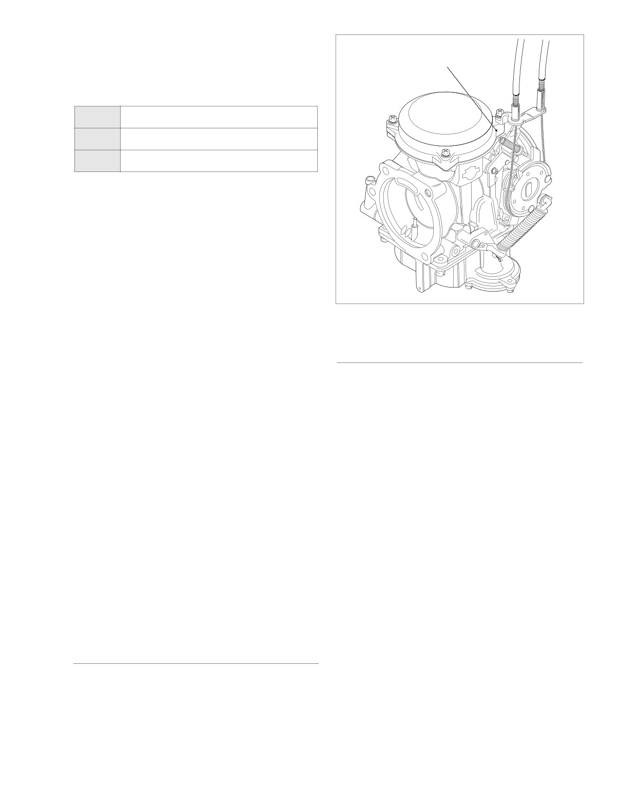
Figure 1-23. Idle Speed Adjustment
engine idling.
c. An overheated plug can be identified by a light
brown, glassy deposit. This condition may be
ENGINE IDLE SPEED
accompanied by cracks in the insulator or by ero-
sion of the electrodes. This condition is caused by
At the 1000 mile (1600 km) service interval, and at every
too lean an air/fuel mixture, a hot running engine,
5000 mile (8000 km) service interval thereafter, inspect the
valves not seating or improper ignition timing. The
engine idle speed as follows:
glassy deposit on the spark plug is a conductor
when hot and may cause high speed misfiring. A
NOTES
plug with eroded electrodes, heavy deposits or a
●
The C.V. carburetor has an enrichener circuit that will
cracked insulator should be replaced.
cause the engine to idle at approximately 1500 rpm with
d. A plug with a white, yellow or light tan to rusty brown
the engine at normal operating temperature and the
powdery deposit indicates balanced combustion.
enrichener knob pulled fully out.
The deposits may be cleaned off at regular intervals
if desired.
●
The increase in idle speed is intended to alert the rider
that the engine is warmed up to normal operating tem-
2.
Set the spark plug gap using a wire-type gauge. Bend
perature and the enrichener knob should be pushed all
the outside of the electrode so only a slight drag on the
the way in.
gauge is felt when passing it between electrodes. Never
make adjustments by bending the center electrode. Set
●
Continuing to use the enrichener when the engine is at
gap on all plugs at 0.038-0.043 in. (0.97-1.09 mm)
full operating temperature WILL CAUSE FOULED
3.
Before installing spark plugs, check condition of threads
PLUGS.
in cylinder head and on plug. If necessary soften depos-
●
TECHNICIAN - Be sure the engine is warmed up to nor-
its with penetrating oil and clean out with a thread
mal operating temperature and the enrichener knob is
chaser.
pushed all the way in BEFORE adjusting engine idle
4.
Install spark plug finger tight and then torque to 12-18 ft-
speed. Be aware that because there are variations in
lbs (16-24 Nm).
individual components, it is possible for a properly
warmed up engine to idle at
2000 rpm with the
enrichener knob pulled PARTIALLY OUT.
ELECTRICAL COMPONENTS
1.
See Figure 1-23. With the engine at normal operating
temperature and the enrichener all the way in
At the 1000 mile (1600 km) service interval, and at every
(enrichener valve closed) adjust the throttle stop screw
5000 mile (8000 km) service interval thereafter, inspect the
so the engine idles at 950-1050 rpm.
operation of all electrical components and switches.
2004 Touring: Maintenance
1-29
HOME
NOTE
ENGINE MOUNTS
To measure engine rpm on models without tachometers, use
At every 10,000 mile (16,000 km) service interval, inspect the
a test tachometer connected to the negative ignition coil ter-
condition and tightness of the stabilizer links and engine
minal.
mounts. Proceed as follows:
NOTE
Raise fuel tank to access top engine stabilizer bolts and jam
nuts. For carbureted models, see Section 4.7 FUEL TANK
CRITICAL FASTENERS
(CARBURETED), PARTIAL REMOVAL, FLHT/C, or FLHR/S.
For fuel injected models, see Section 9.4 FUEL TANK (FUEL
INJECTED), PARTIAL REMOVAL, FLHT/C/U/I, FLTRI, or
At the 1000 mile (1600 km) service interval, and at every
FLHR/C/S/I.
10,000 mile (16,000 km) service interval thereafter, inspect
the tightness of all critical fasteners. Replace fastener if dam-
aged or missing.
Top
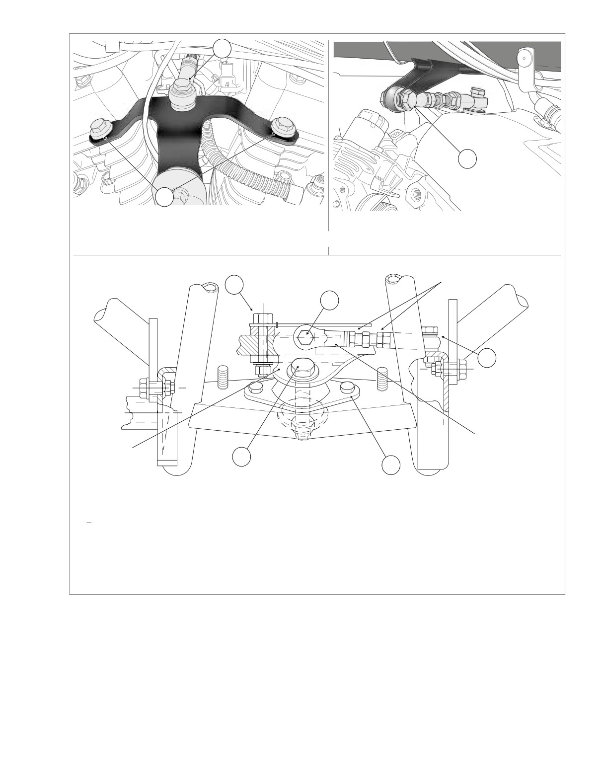
● On left side of vehicle, tighten top engine mounting
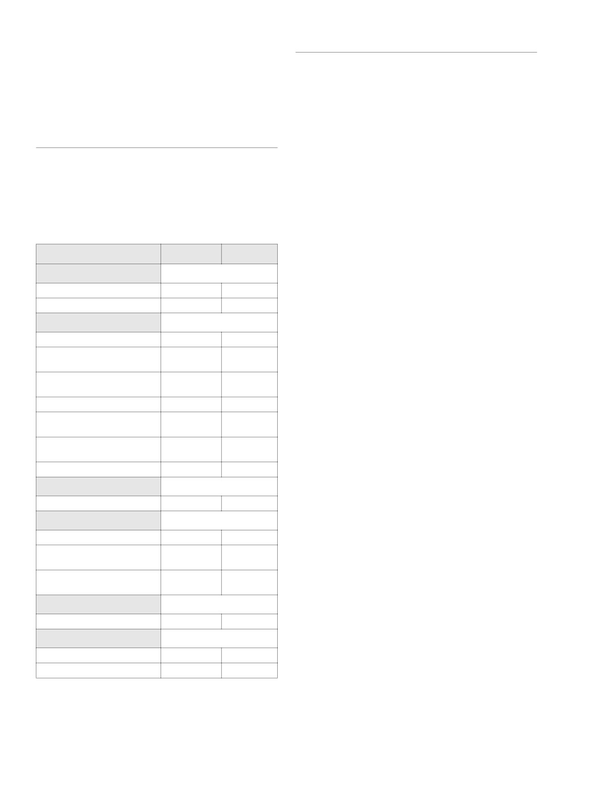
Table 1-6. Critical Fastener Torque
bracket bolts to front and rear cylinder heads to 35-40 ft-
lbs (48-54 Nm). See A of Figure 1-24.
Fastener
ft/in-lbs
Nm
● Top stabilizer link - tighten eyelet bolt to top engine
Axle
mounting bracket to 18-22 ft-lbs (24-30 Nm). See B of
Figure 1-24.
Front axle nut
50-55 ft-lbs
68-75 Nm
● Moving to right side of vehicle, tighten eyelet bolt to
Rear axle cone nut
95-105 ft-lbs
129-142 Nm
frame weldment to 18-22 ft-lbs (24-30 Nm). See C of Fig-
Brakes
ure 1-24.
Banjo Bolts
17-22 ft-lbs
23-30 Nm
● Verify tightness of jam nuts on top stabilizer link.
Front Brake Disc Mounting
16-24 ft-lbs
22-33 Nm
Screws
Bottom
Front Brake Caliper Mounting
28-38 ft-lbs
38-52 Nm
Bolts
● Front stabilizer link - on left side of vehicle, tighten eyelet
Brake Caliper Pad Pins
180-200 in-lbs
20-23 Nm
bolt to frame weldment to 18-22 ft-lbs (24-30 Nm). See D
of Figure 1-24.
Rear Brake Disc Mounting
30-45 ft-lbs
41-61 Nm
Screws
● Moving to right side of vehicle, tighten eyelet bolt to
Rear Master Cylinder Mounting
block on front engine mounting bracket to 18-22 ft-lbs
30-40 ft-lbs
41-54 Nm
Nut
(24-30 Nm). See E of Figure 1-24.
Reservoir Cover Screws
6-8 in-lbs
0.7-0.9 Nm
● Verify tightness of jam nuts on front stabilizer link.
Front Forks
● Tighten center front engine mounting bracket to rubber
mount bolt to 15-20 ft-lbs (20-27 Nm). See F of Figure 1-
Axle Holder Nuts
132-180 in-lbs
14.9-20.3 Nm
24.
Hand Controls
● Tighten the two front engine mount to frame crossmem-
ber bolts to 15-20 ft-lbs (20-27 Nm). See G of Figure 1-
Clutch Lever/Handlebar Clamp
60-80 in-lbs
6.8-9.0 Nm
24.
Master Cylinder/Handlebar
60-80 in-lbs
6.8-9.0 Nm
● Tighten two engine to front engine mounting bracket
Clamp Screws
bolts to 33-38 ft-lbs (45-52 Nm). See H of Figure 1-24.
Upper/Lower Switch Housing
35-45 in-lbs
4-5 Nm
Screws
● Tighten four engine to transmission bolts to 30-35 ft-lbs
(41-48 Nm).
Handlebars
NOTE
Lower Clamp (Riser) Bolts
30-40 ft-lbs
40.7-54.2 Nm
Install fuel tank. For carbureted models, see Section 4.7
Pivot Shaft
FUEL TANK (CARBURETED), INSTALLATION (AFTER
PARTIAL REMOVAL), FLHT/C, or FLHR/S. For fuel injected
Locknuts
40-45 ft-lbs
54-61 Nm
models, see Section 9.4 FUEL TANK (FUEL INJECTED),
Swingarm Bracket Bolts
34-42 ft-lbs
46-57 Nm
INSTALLATION (AFTER PARTIAL REMOVAL), FLHT/C/U/I,
FLTRI, or FLHR/C/S/I.
1-30
2004 Touring: Maintenance
HOME
B
C
A
LEFT SIDE
RIGHT SIDE
Top Stabilizer Link and Engine Mounting Bracket
f2181x2x
f2111x2x
Jam Nut
H
E
D
Front
Stabilizer Link
Front Engine
F
Mounting Bracket
G
f1303x2x
Front Stabilizer Link and Engine Mounting Bracket
Top
Bottom
A Top Engine Mounting Bracket to Cylinder Heads
D Eyelet to Frame Weldment
B Eyelet to Top Engine Mounting Bracket
E Eyelet to Front Engine Mounting Bracket
C Eyelet to Frame Weldment
F Front Engine Mounting Bracket to Rubber Mount
G Front Engine Mount to Frame Crossmember
H Engine to Front Engine Mounting Bracket
Figure 1-24. Engine Mounting Bracket Bolts
2004 Touring: Maintenance
1-31
HOME
FRONT FORK OIL
ROAD TEST
Overhaul the front fork assembly and replace the fork oil at
At the 1000 mile (1600 km) service interval, and at every
every 50,000 mile (80,000 km) service interval. For detailed
5000 mile (8000 km) service interval thereafter, perform a
instructions, see Section 2.15 FRONT FORKS.
road test after all work is complete.
1-32
2004 Touring: Maintenance
HOME
SPECIFICATIONS
2.1
DIMENSIONS (IN.)
DIMENSIONS (MM)
FLHT/C/U
FLHR/C/S
FLTR
FLHT/C/U
FLHR/C/S
FLTR
Wheel Base
63.5
63.5
63.5
Wheel Base
1613
1613
1613
Overall Length
93.7/97.5/98.3
93.7
93.7
Overall Length
2380/2476/2497
2380
2380
Overall Width
39.0
34.45/34.45/39.40
35.75
Overall Width
990
875/875/1001
908
Road Clearance
5.12
5.12/5.12/4.70
5.12
Road Clearance
130
130/130/119
130
Overall Height
61.0
55.06/55.06/46.40
55.0
Overall Height
1549
1399/1399/1179
1397
Saddle Height*
27.3
27.3/26.9/26.1
26.9
Saddle Height*
693
693/683/663
683
* With 180 Lb. Rider
* With 81.6 kg Rider
WEIGHT (LBS.)
WEIGHT (KG)
FLHT/C/U
FLHR/C/S
FLTR
FLHT/C/U
FLHR/C/S
FLTR
DRY WEIGHT**
758/776/788
723/710/721
731
DRY WEIGHT**
344/352/358
328/322/327
332
GVWR
1259
1259
1259
GVWR
571
571
571
GAWR - Front
500
500
500
GAWR - Front
227
227
227
GAWR - Rear
827
827
827
GAWR - Rear
375
375
375
** As shipped from the factory
** As shipped from the factory
NOTE
Gross Vehicle Weight Rating (GVWR) (maximum allowable
loaded vehicle weight) and corresponding Gross Axle Weight
Ratings (GAWR) are given on a label located on the inside of
the right front frame downtube.
CAPACITIES (U.S.)
CAPACITIES (METRIC)
FLHT/C/U
FLHR/C/S
FLTR
FLHT/C/U
FLHR/C/S
FLTR
Fuel Tank (gallons)
Fuel Tank (liters)
Total***
5
5
5
Total***
18.9
18.9
18.9
Reserve
0.9
0.9
0.9
Reserve
3.4
3.4
3.4
Oil Tank (quarts)
Oil Tank (liters)
with filter
4
4
4
with filter
3.78
3.78
3.78
Transmission
Transmission
(Ounces, approximate)
20-24
20-24
20-24
(Milliliters)
591-710
591-710
591-710
Primary Chaincase
Primary Chaincase
(Ounces, approximate)
32
32
32
(Milliliters)
946
946
946
Left
Right
Left
Right
Left
Right
Left
Right
Left
Right
Left
Right
Front Fork (Ounces)
Front Fork (Milliliters)
10.0
11.1
11.1
11.1
10.0
11.1
295
328
328
328
295
328
*** Includes Reserve on Carbureted Models
*** Includes Reserve on Carbureted Models
2004 Touring: Chassis
2-1