Harley Davidson 2004 Touring Models. Service Manual - page 16
HOME
Test 5.22 (Part 2 of 2)
TP SENSOR: DTC P0122, P0123
Continued from Test 5.22 (Part 1 of 2).
With ignition key OFF, disconnect ECM connector [78B]. Turn
ignition key ON. Voltage greater than 0 volts across terminal 24
and terminal 26 on Breakout Box?
YES
NO
Repair short
Measure resistance between
between GY/V signal
ECM terminal 24 on Breakout Box and
wire and 12 volts.
TP sensor connector [88B] Terminal C.
Less than 0.5 ohm?
3
YES
NO
Measure resistance from TP
Repair open
sensor connector [88B]
GY/V
Terminal C to Terminal B.
signal wire.
Less than 1.0 megohm?
3
YES
NO
Repair short
Replace
between R/W and
TP sensor.
2
GY/V signal wire.
At some point in the flow chart you
may be instructed to jump directly
Clear codes using speedometer self diagnostics.
to a the box with the bold asterisk.
See 5.6 SPEEDOMETER SELF DIAGNOSTICS.
Disregard the asterisk (but not the
Confirm proper operation with no check engine
instruction box) if your normal pro-
lamp.
gression through the chart brings
you to this location.
5-84
2004 Touring: Engine Management (EFI)
HOME
DTC P0261, P0262, P0263, P0264
5.23
GENERAL
s0472x9x
Fuel Injectors
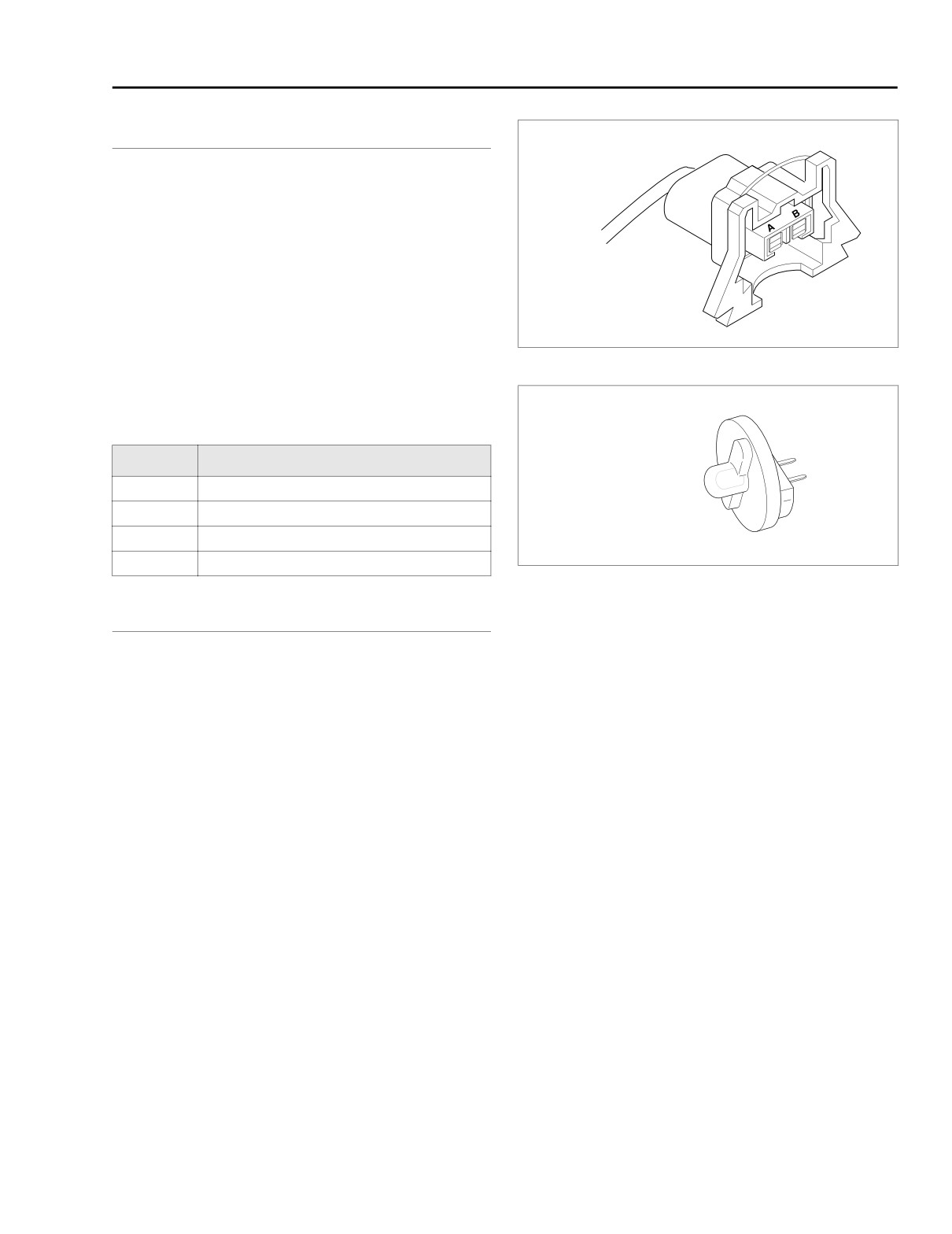
The fuel injectors are solenoids that allow pressurized fuel
into the intake tract. The injectors are timed to the engine
cycle and triggered sequentially. The power for the injectors
comes from the system relay. The system relay also provides
power for the fuel pump and the ignition coil. The ECM pro-
vides the path to ground to trigger the injectors.
NOTE
ECM fuse and system relay failures or wiring harness prob-
lems will cause 12 volt power to be lost to both injectors, igni-
Figure 5-50. Fuel Injector Connector
tion coils and fuel pump.
HD34730-2C
Table 5-36. Code Description
DTC
DESCRIPTION
P0261
Front injector open/low
P0262
Front injector high
P0263
Rear injector open/low
P0264
Rear injector high
Figure 5-51. Fuel Injector Test Lamp
(Part No. HD-34730-2C)
DIAGNOSTICS
Diagnostic Notes
The reference numbers below correlate with the circled num-
bers on the Test 5.23 flow charts.
1. See Touring Service Manual for all service information.
2. Use HARNESS CONNECTOR TEST KIT (Part No. HD-
41404), purple pin probe and patch cord.
3. Connect a BREAKOUT BOX
(Part No. HD-43876)
between EFI wire harness and ECM. See 5.7 BREAK-
OUT BOX: EFI.
2004 Touring: Engine Management (EFI)
5-85
HOME
f2208h8x
[62B]
System relay
Y/GN
[78A]
[78B]
BE/GY
GN/O
W/BK
[13A] [13B]
Fuel pump
O/GY
System relay
GN/O
Y/GN
15 amp
fuel pump
W/Y
fuse
[141B] [141A]
[84B] [84A]
BK
Y/GN
Power gnd.
Coil R
Y/BE
[85B] [85A]
GY/BE
Ignition
Switch power
Y/BE
coil
BE/O
ECM
W/BK
[83B] [83A]
Inj. R
GN/GY
BE/GY
+
-
15 amp
Inj. F
W/Y
Battery
ECM fuse
R
BK
40 Amp
R
R
Maxi Fuse
R/BK
12
12
BK
11
11
DCBA
10
10
[33B]
Ion sense
9
9
[33A]
Power gnd.
15 amp
8
8
Coil F
BE/O
7
7
IGN fuse
6
6
Ignition
5
5
GY
Constant power
switch
4
4
3
3
2
2
W/BK
1
1
12 11 10 9 8 7 6 5 4 3
2
1
[1B]
12 11 10 9 8 7 6 5 4 3
2
1
[1A]
[8B] [8A]
BK
12 11 10 9 8 7 6 5 4 3
2
1
[22A]
BK
12 11 10 9 8 7 6 5 4 3
2
1
[22B]
Engine stop
switch
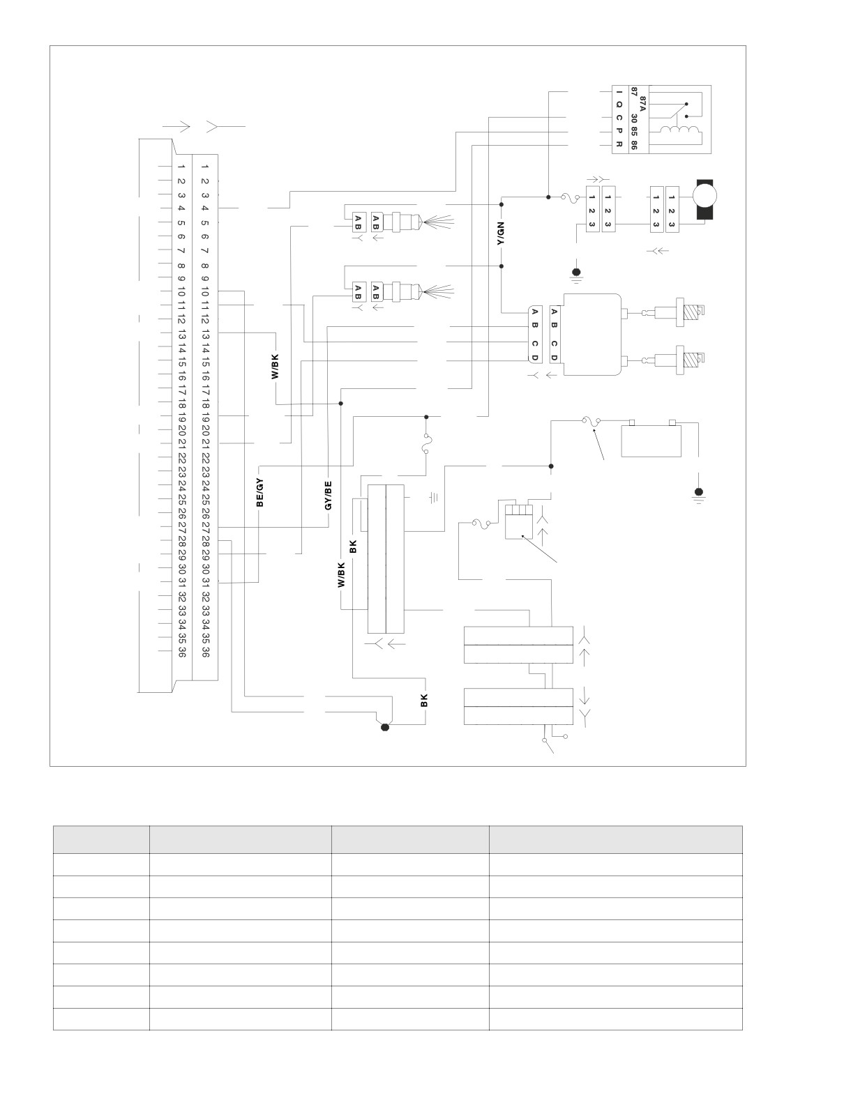
Figure 5-52. Battery Voltage Circuit (FLTR, FLHT/C/U)
Table 5-37. Wire Harness Connectors in Figure 5-52.
NO.
DESCRIPTION
TYPE
LOCATION
[1]
Main to Interconnect Harness
12-Place Deutsch (Black)
Inner Fairing (Right Fairing Bracket)
[8]
Main to EFI Harness
12-Place Deutsch (Gray)
Under Right Side Cover
[22]
Right Handlebar Switches
12-Place Deutsch (Black)
Inner Fairing (Right Fairing Support Brace)
[33]
Ignition/Light Key Switch
4-Place Packard
Inner Fairing (Top Fork Bracket)
[78]
ECM
36-Place Packard
Under Right Side Cover
[83]
Ignition Coil
4-Place Packard
Below Fuel Tank (Left Side)
[84]
Front Injector
2-Place Packard
Below Fuel Tank (Left Side)
[85]
Rear Injector
2-Place Packard
Below Fuel Tank (Left Side)
5-86
2004 Touring: Engine Management (EFI)
HOME
f2208m8x
[62B]
System relay
Y/GN
[78A]
[78B]
BE/GY
GN/O
W/BK
Fuel pump
Y/GN
Y/GN
15 amp
GN/O
System relay
fuel pump
W/Y
fuse
[141B] [141A]
[84B] [84A]
BK
Y/GN
Power gnd.
Coil R
Y/BE
[85B] [85A]
GY/BE
Ignition
Switch power
Y/BE
coil
BE/O
ECM
W/BK
[83B] [83A]
BE/GY
Inj. R
GN/GY
15 amp
+
-
W/Y
ECM fuse
Inj. F
Battery
R
BK
R
40 Amp
R
R/BK
Maxi Fuse
12
12
BK
11
11
I B A
10
10
[33B]
Ion sense
9
9
[33A]
Power gnd.
8
8
15 amp
Coil F
BE/O
7
7
IGN fuse
6
6
Ignition
5
5
GY
Constant power
switch
4
4
3
3
2
2
W/BK
1
1
12 11 10 9 8 7
6543
2
1
[22A]
12 11 10 9 8 7
6543
2
1
[22B]
[8B] [8A]
12-Place on
FLHP Only
BK
Engine stop
BK
switch
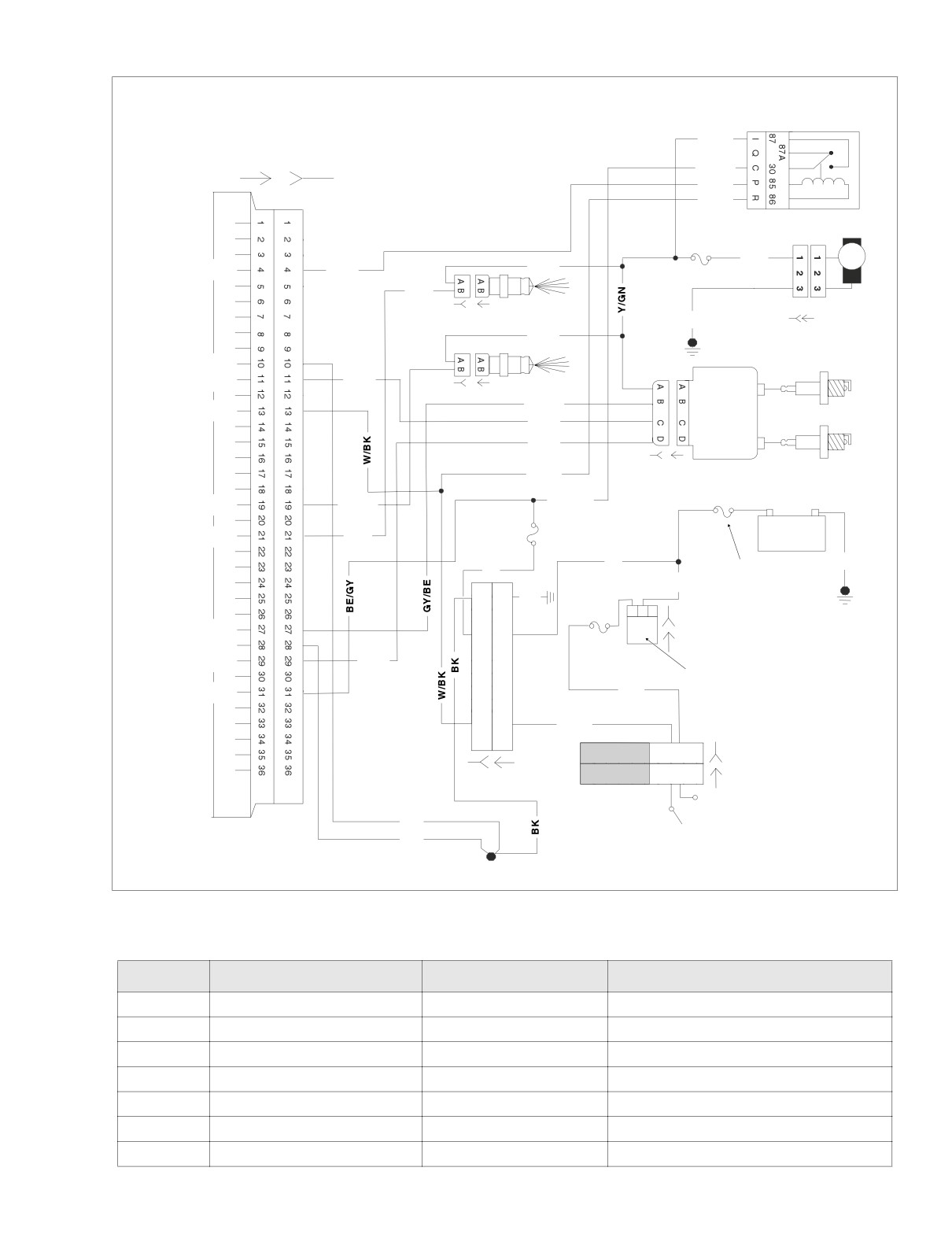
Figure 5-53. Battery Voltage Circuit (FLHR/C/S)
Table 5-38. Wire Harness Connectors in Figure 5-53.
NO.
DESCRIPTION
TYPE
LOCATION
[8]
Main to EFI Harness
12-Place Deutsch (Gray)
Under Right Side Cover
[22]
Right Handlebar Switches
12-Place Deutsch (Black)
Inside Headlamp Nacelle
[33]
Ignition/Light Key Switch
3-Place Packard
Under Console
[78]
ECM
36-Place Packard
Under Right Side Cover
[83]
Ignition Coil
4-Place Packard
Below Fuel Tank (Left Side)
[84]
Front Injector
2-Place Packard
Below Fuel Tank (Left Side)
[85]
Rear Injector
2-Place Packard
Below Fuel Tank (Left Side)
2004 Touring: Engine Management (EFI)
5-87
HOME
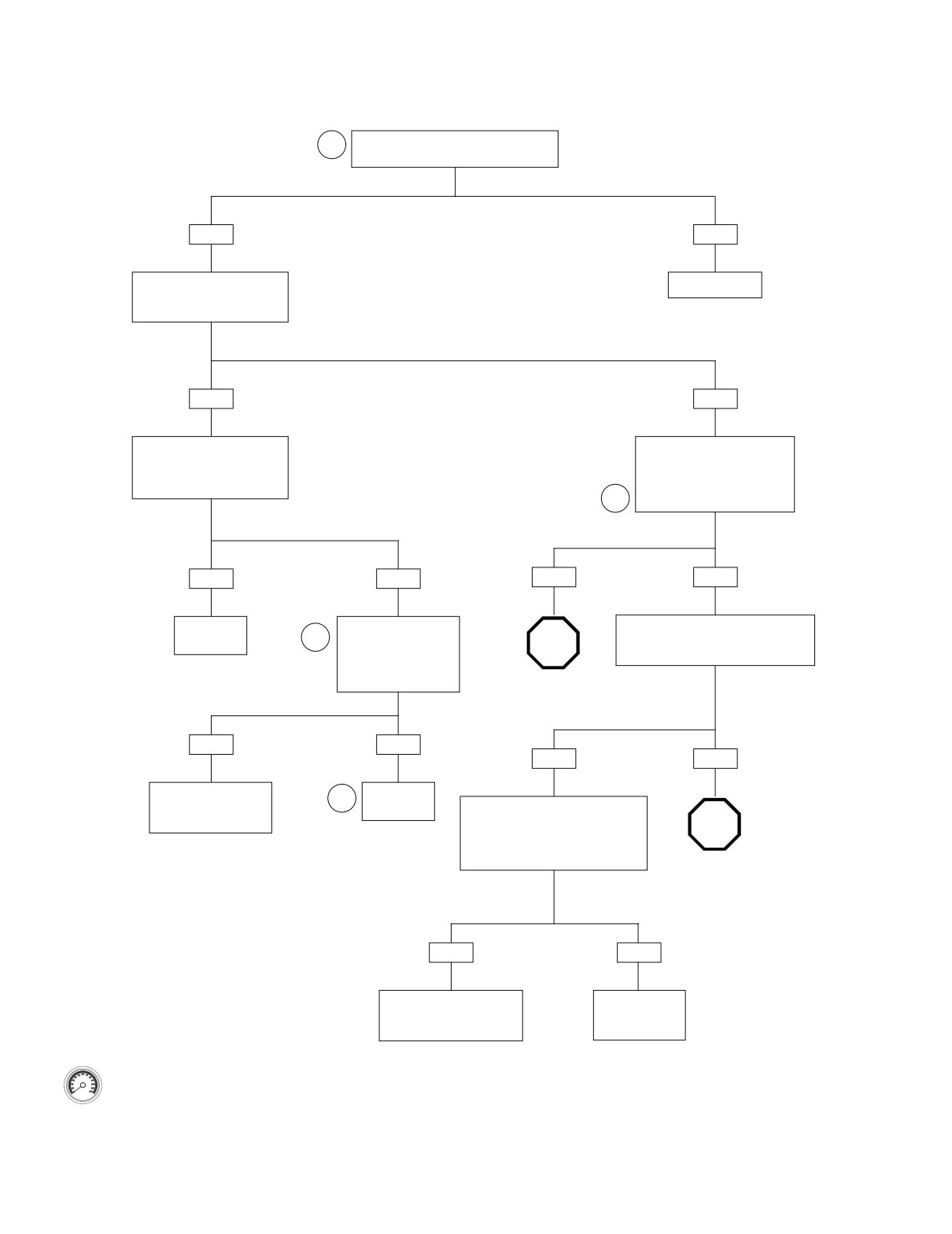
Test 5.23 (Part 1 of 3)
FUEL INJECTORS: DTC P0261, P0262, P0263, P0264
Is wire bail on connector securely
1
attached to the fuel injector?
YES
NO
See Figure 5-51. Using Fuel
Reconnect.
Injector Test Lamp, crank
engine. Does lamp flash?
YES
NO
Recheck connections.
Check Terminal A (Y/GN wire)
Perform 5.8 WIGGLE TEST
on injector connector to ground.
to check for intermittents.
Voltage equivalent to
Intermittents present?
battery voltage for 2 seconds
after key ON?
2
YES
NO
YES
NO
Repair
Measure resistance of
Check for 12 volts at terminal 87 of sys-
intermittent.
2
suspect injector across
tem relay during first 2 seconds after
STOP
injector terminals.
key ON. Correct voltage present?
Resistance
10.0-25.0 ohms?
Go to Test 5.23 (Part 2 of 3).
YES
NO
YES
NO
Check for loose
Replace
or corroded terminals
1
injector.
System relay OK. Measure
in harness.
resistance between terminal 87 of
STOP
system relay and Terminal A
(Y/GN wire) at injector connector.
Resistance less than 0.5 ohm?
Go to Test 5.23
(Part 3 of 3).
YES
NO
Perform 5.8 WIGGLE TEST
Find and repair
to check for intermittents.
bad connection
Repair as necessary.
or open wire.
Clear codes using speedometer self diagnostics.
See 5.6 SPEEDOMETER SELF DIAGNOSTICS.
Confirm proper operation with no check engine
lamp.
5-88
2004 Touring: Engine Management (EFI)
HOME
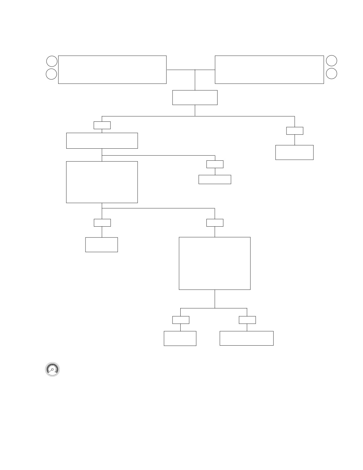
Test 5.23 (Part 2 of 3)
FUEL INJECTORS: DTC P0261, P0262, P0263, P0264
FRONT INJECTOR: DTC P0261 or P0262.
REAR INJECTOR: DTC P0263 or P0264.
2
2
Measure resistance between Breakout Box terminal 21
Measure resistance between Breakout Box terminal 19
3
(W/Y wire) and Terminal B of front injector connector
(GN/GY wire) and Terminal B of rear injector connector
3
[84B].
[85B].
Resistance
less than 0.5 ohm?
YES
NO
Check for continuity between terminal
10 and ground.
Repair open or
poor connection.
Front injector codes: Check continuity
NO
between terminal 21 and terminal 10.
or
Rear injector codes: Check continu-
Repair open
ity between terminal 19 and terminal
10.
Continuity present?
YES
NO
Repair short
Check for voltage with key on.
to ground.
Front injector codes: Check
Breakout Box terminal 21.
Rear injector codes: Check
Breakout Box terminal 19.
Voltage present after 2 seconds?
YES
NO
Repair short
Replace ECM. Reprogram
to voltage.
and learn password.
Clear codes using speedometer self diagnostics.
See 5.6 SPEEDOMETER SELF DIAGNOSTICS.
Confirm proper operation with no check engine
lamp.
2004 Touring: Engine Management (EFI)
5-89
HOME
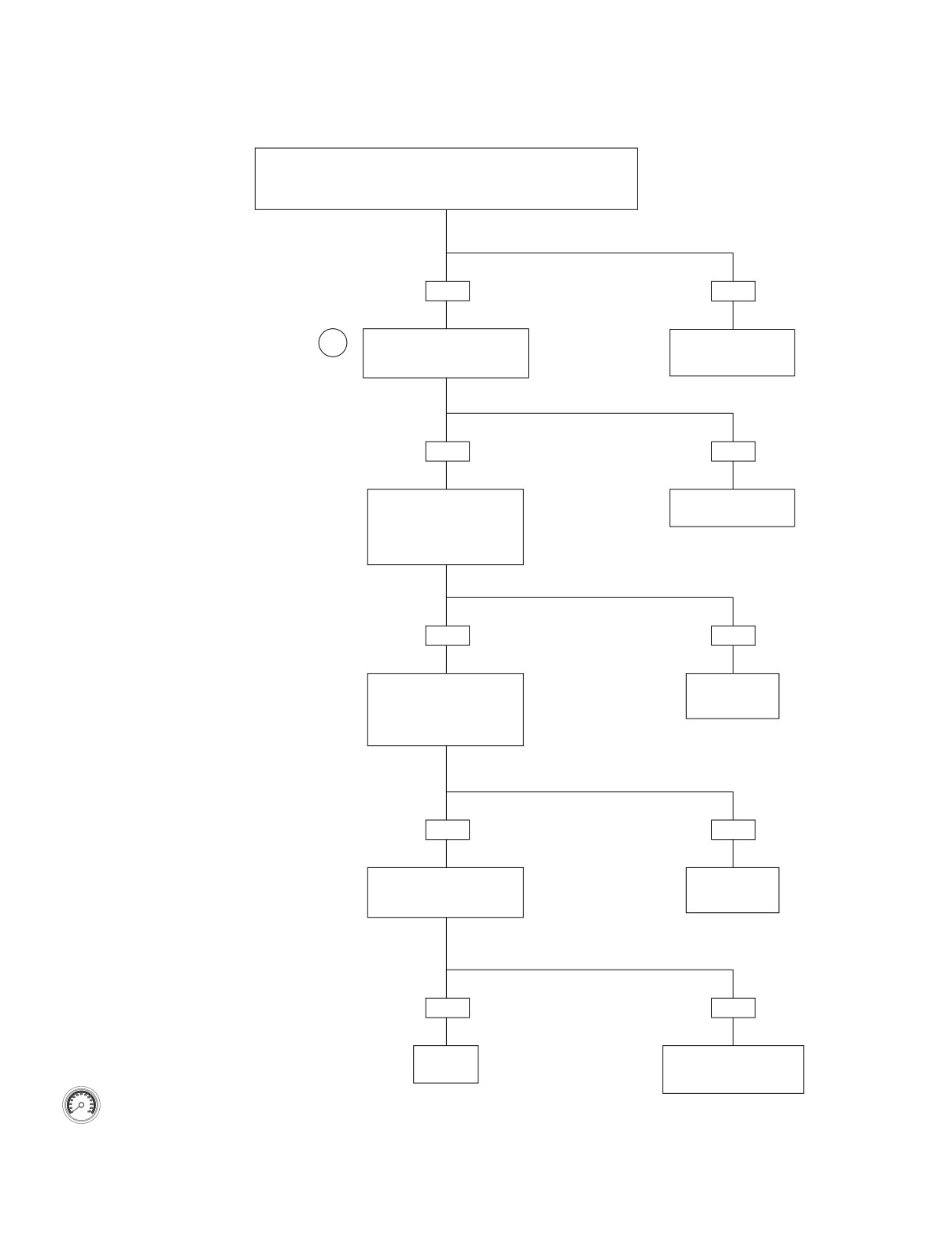
Test 5.23 (Part 3 of 3)
FUEL INJECTORS: DTC P0261, P0262, P0263, P0264
Continued from Test 5.23 (Part 1 of 3).
Check for 12 volts at terminal 30 of the system relay.
Correct voltage present?
YES
NO
Check for 12 volts at terminal 86
Find and repair open on
3
of the system relay.
BE/GY wire between
Correct voltage present?
fuse and relay.
YES
NO
Measure resistance between
See 5.11 NO ECM
terminal 86 of the system
POWER.
relay and ECM terminal 13 on
Breakout Box.
Resistance less than 0.5 ohm?
YES
NO
Measure resistance between
Find and repair
terminal 85 of the system relay
open on W/BK
and ECM terminal 4 on Break-
wire.
out Box.
Resistance less than 0.5 ohm?
YES
NO
Install known good relay.
Find and repair
Does fuel pump run for first
open on GN/O
2 seconds after key ON?
wire.
YES
NO
Replace
Reinstall original relay.
relay
Replace ECM. Reprogram
Clear codes using speedometer self diagnostics.
and learn password.
See 5.6 SPEEDOMETER SELF DIAGNOSTICS.
Confirm proper operation with no check engine
lamp.
5-90
2004 Touring: Engine Management (EFI)
HOME
DTC P0373, P0374
5.24
GENERAL
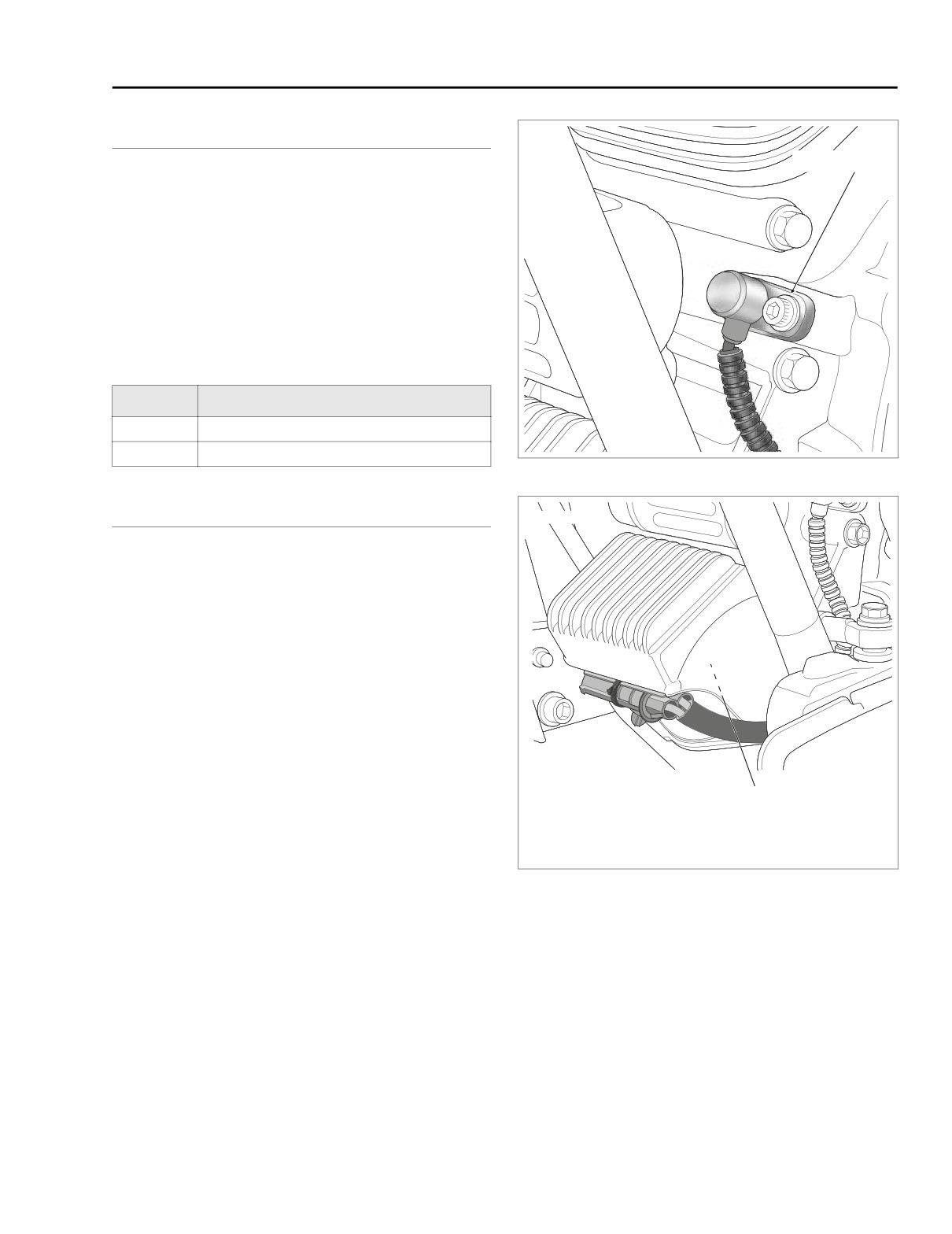
f2217x8x
Socket Screw
CKP Sensor
If the crank position sensor (CKP sensor) signal is weak or
absent, diagnostic trouble codes P0373 or P0374 will be set.
NOTE
If signal is not detected or cannot synchronize (DTC P0374),
engine will not start.
Table 5-39. Code Description
DTC
DESCRIPTION
P0373
CKP sensor intermittent
P0374
CKP sensor synch error
Figure 5-54. Crankshaft Position Sensor
DIAGNOSTICS
f2256x8x
Diagnostic Tips
● Engine must be cranked for more than five seconds with-
out CKP signal to set code.
Diagnostic Notes
The reference numbers below correlate with the circled num-
bers on the Test 5.24 flow chart.
1. Connect BREAKOUT BOX (Part No. HD-43876) to ECM
wire harness only (leave ECM disconnected). See 5.7
BREAKOUT BOX: EFI.
2. One megohm is very high resistance. Some meters will
Crankshaft
read ∞, OL, etc.
Position Sensor
Connector [79]
3. Use HARNESS CONNECTOR TEST KIT (Part No. HD-
Under Voltage Regulator
41404), brown socket probes and patch cords.
4. For testing purposes, install sensor without running wir-
Figure 5-55. Voltage Regulator (Left Side View)
ing along normal path. Disconnect and route wiring prop-
erly if system is now OK.
2004 Touring: Engine Management (EFI)
5-91
HOME
s0453x9x
CKP
sensor
1
2
[79A]
[79B]
1
2
[78B]
10
12
28
30
[78A]
ECM
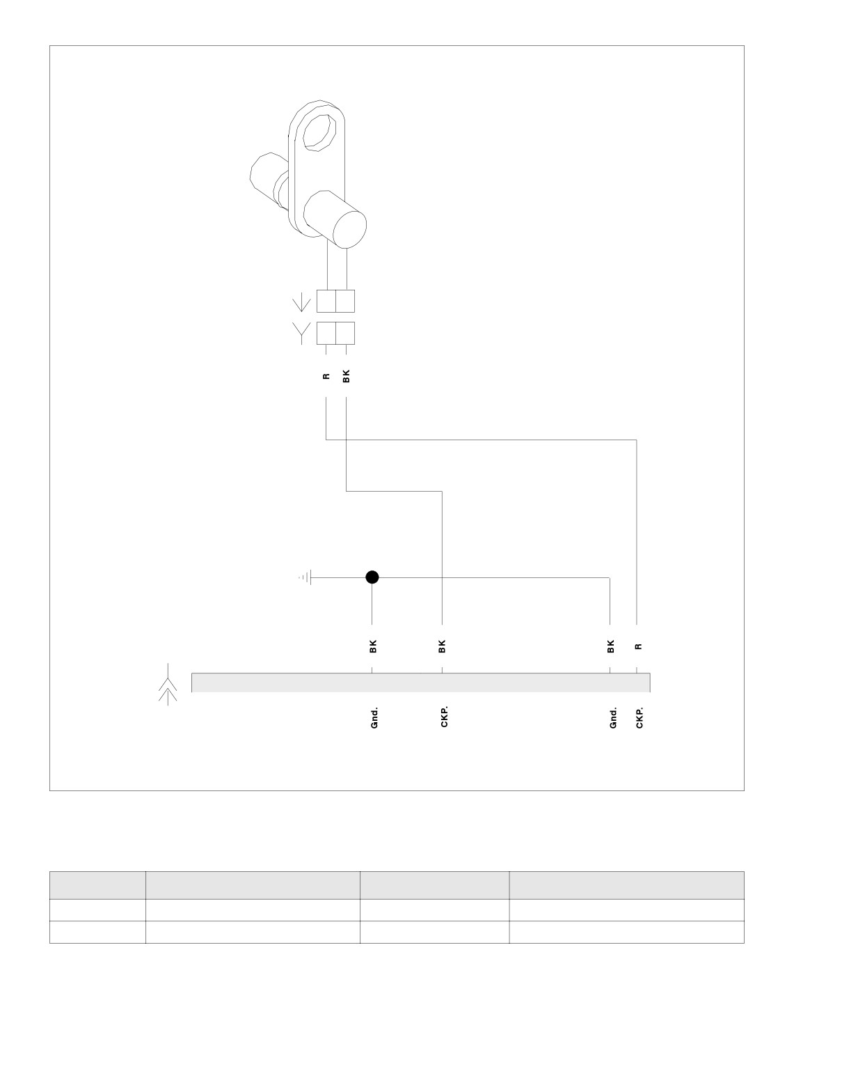
Figure 5-56. CKP Circuit
Table 5-40. Wire Harness Connectors in Figure 5-56.
NO.
DESCRIPTION
TYPE
LOCATION
[78]
ECM
36-Place Packard
Under Right Side Cover
[79]
CKP Sensor
2-Place Mini-Deutsch
Under Right Side Cover
5-92
2004 Touring: Engine Management (EFI)
HOME
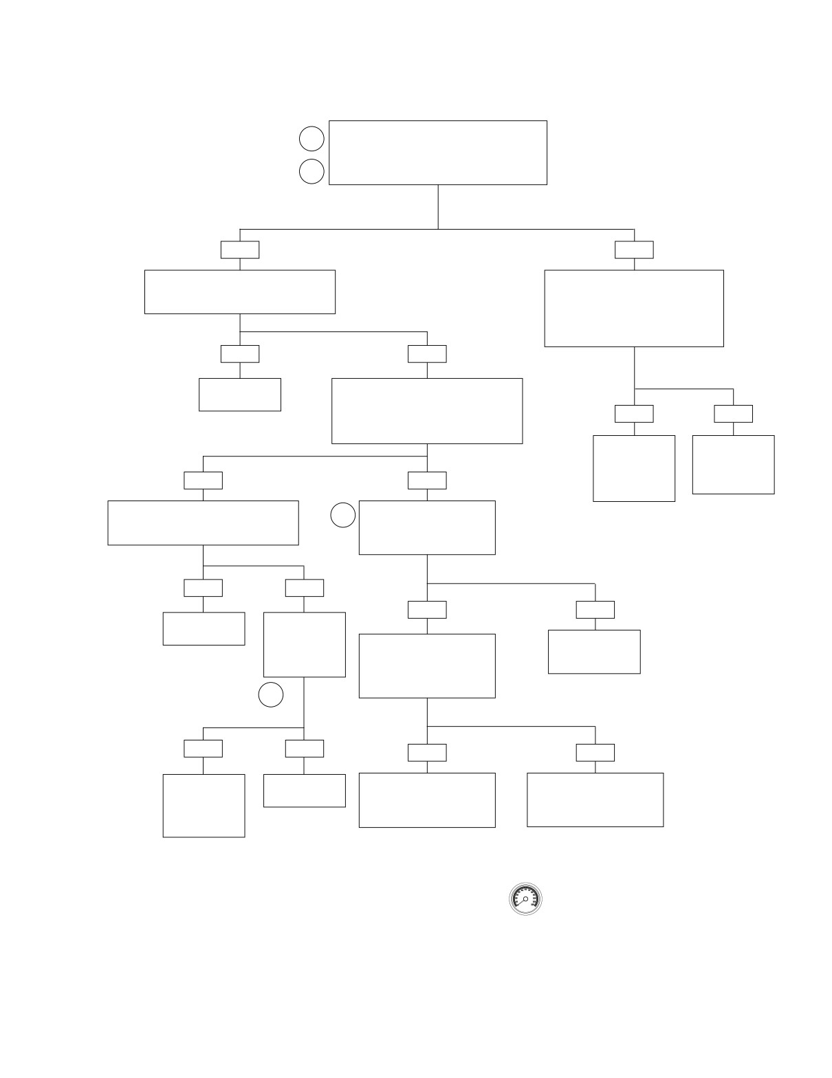
Test 5.24
CKP SENSOR: DTC P0373, P0374
Connect Breakout Box to harness only,
1
leaving ECM disconnected.
Measure resistance between terminals 30 and 28
and between terminals 12 and 28 on Breakout Box.
2
Resistance more than 1 megohm?
YES
NO
Check for intermittent connection, pinched
Disconnect connector [79]. Leaving
or damaged wires, and loose CKP sensor
ECM disconnected, measure resistance
fasteners. Conditions found?
between terminals 12 and 28 and
terminals 30 and 28 on Breakout Box.
Continuity to ground
(less than 1 megohm resistance)?
YES
NO
Repair as
Connect DVOM to terminals 12 and 30
necessary.
on Breakout Box.
Set DVOM to AC volts and crank engine.
YES
NO
Does DVOM read 1 VAC minimum
during cranking?
Repair short to
Replace
ground on R or
CKP sensor.
BK wire between
See Touring Ser-
YES
NO
connectors [78B]
vice Manual.
and [79B].
With DVOM still connected, check for inter-
Connect DVOM at Terminals 1
mittents using 5.8 WIGGLE TEST. Intermit-
3
and 2 of connector [79A].
tents present?
Does DVOM read 1 VAC
minimum while cranking?
YES
NO
YES
NO
Repair as
Install known
necessary.
good CKP sen-
sor. Clear codes
Check for continuity between
Replace CKP sen-
sor. See Touring
and retest. DTC
Terminal 1 of connector [79B]
Service Manual.
P0373 or P0374
and terminal 30 on Breakout
Box.
Continuity present?
4
YES
NO
YES
NO
Reinstall original
Replace CKP
Repair open on BK wire
Repair open on R wire
CKP sensor.
sensor
between Terminal 2 of
between Terminal 1 of
Replace ECM.
connector [79B] and
connector [79B] and
Reprogram and
terminal 12 of Breakout Box.
terminal 30 of Breakout Box.
learn password.
Clear codes using speedometer self diagnostics.
See 5.6 SPEEDOMETER SELF DIAGNOSTICS.
Confirm proper operation with no check engine
lamp.
2004 Touring: Engine Management (EFI)
5-93
HOME
DTC P0501, P0502
5.25
GENERAL
7951
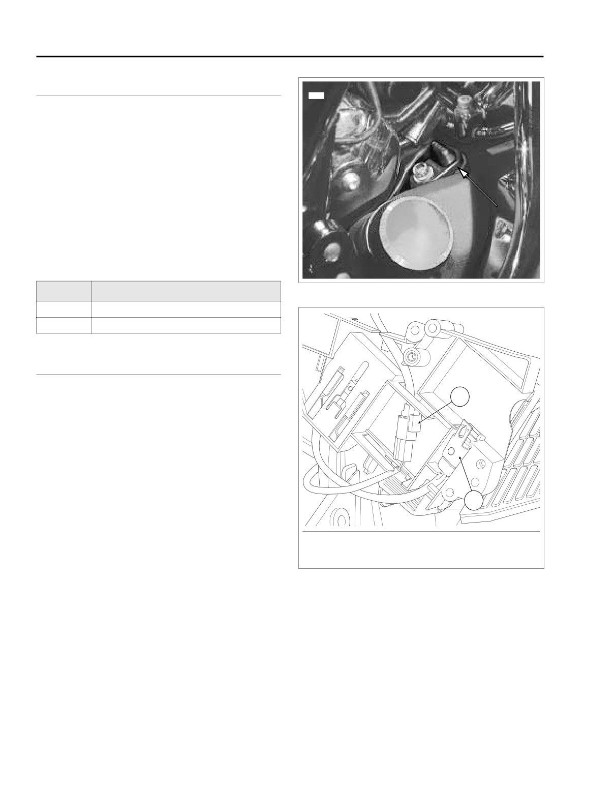
Vehicle Speed Sensor
See Figure 5-57. The vehicle speed sensor is powered and
monitored by the ECM. The ECM processes the vehicle
speed signal and transmits this signal to the TSM/TSSM and
speedometer through serial data.
NOTE
When the vehicle speed is greater than 0, the closed loop idle
speed control is inhibited.
Table 5-41. Code Description
DTC
DESCRIPTION
Figure 5-57. Vehicle Speed Sensor
P0501
VSS sensor low
f2183x8x
P0502
VSS sensor high/open
DIAGNOSTICS
1
Diagnostic Notes
The reference numbers below correlate with the circled num-
bers on the Test 5.25 flow charts.
1. The speedometer has a built-in diagnostic mode. See
2.3 SPEEDOMETER SELF DIAGNOSTICS.
2. Use HARNESS CONNECTOR TEST KIT (Part No. HD-
41404), black pin probe and patch cord.
2
3. Connect BREAKOUT BOX
(Part No. HD-43876)
between wire harness and ECM. See 5.7 BREAKOUT
BOX: EFI.
1. Vehicle Speed Sensor [65]
2. P&A Security Siren [142]
Figure 5-58. Electrical Bracket (Inboard Side)
5-94
2004 Touring: Engine Management (EFI)
HOME
f2208v8x
Vehicle speed
To Cruise and Sound System
sensor
R
A
A
R/W
W
B
B
W/GN
BK
C
C
BK
[65A]
[65B]
Speedometer
To TP, MAP Sensors
[39A]
[39B]
2
LGN/V
[78B]
5
10
14
33
[78A]
ECM
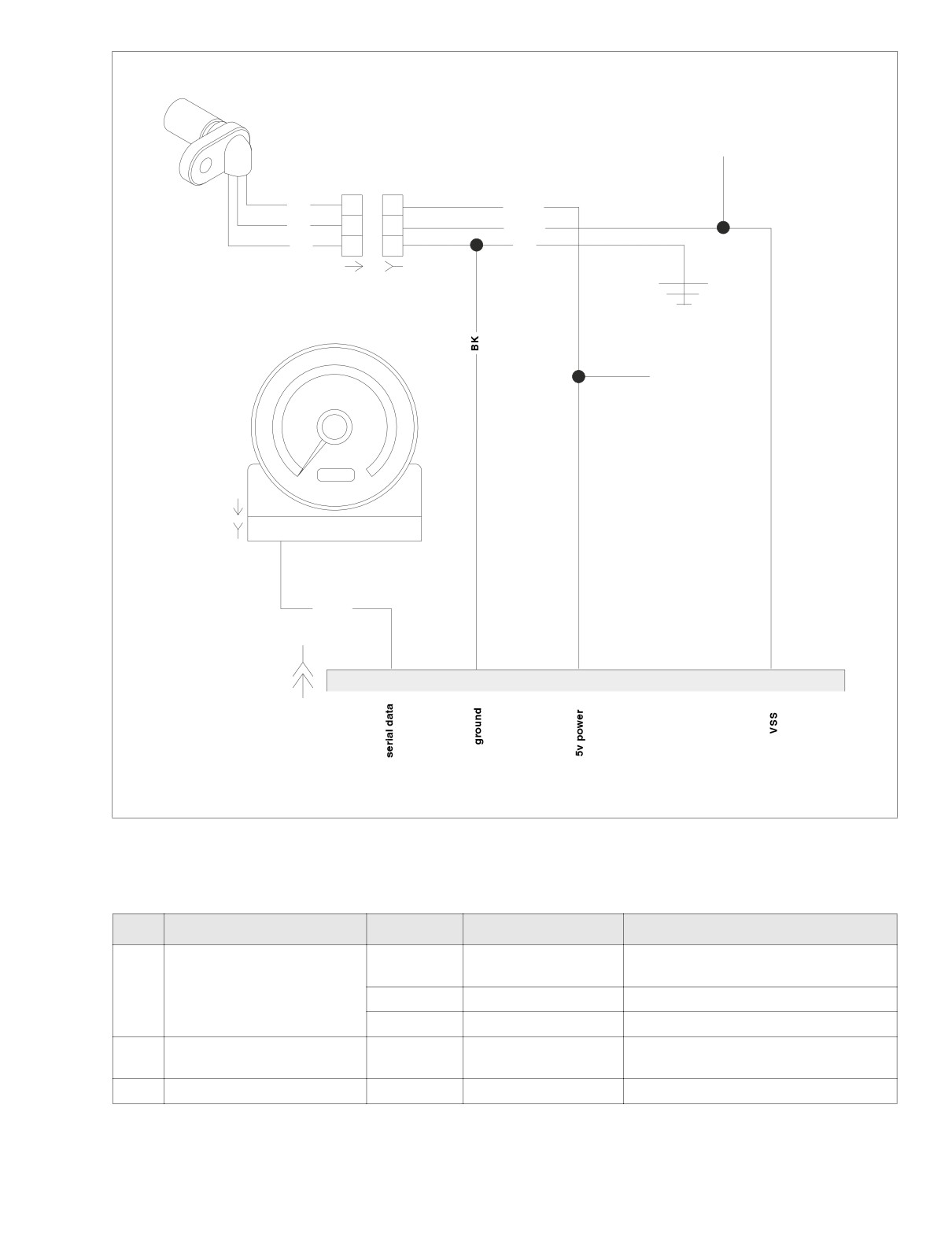
Figure 5-59. Vehicle Speed Sensor Circuit
Table 5-42. Wire Harness Connectors in Figure 5-59.
NO.
DESCRIPTION
MODEL
TYPE
LOCATION
Under Instrument Bezel
FLTR
12-Place Packard
(Back of Speedometer)
[39]
Speedometer
FLHT/C/U
12-Place Packard
Inner Fairing (Back of Speedometer)
FLHR/C/S
12-Place Packard
Back of Speedometer (Under Console)
Under Right Side Cover
[65]
Speedometer Speed Sensor
All
3-Place Deutsch
(Behind Electrical Bracket)
[78]
ECM
All
36-Place Packard
Under Right Side Cover
2004 Touring: Engine Management (EFI)
5-95
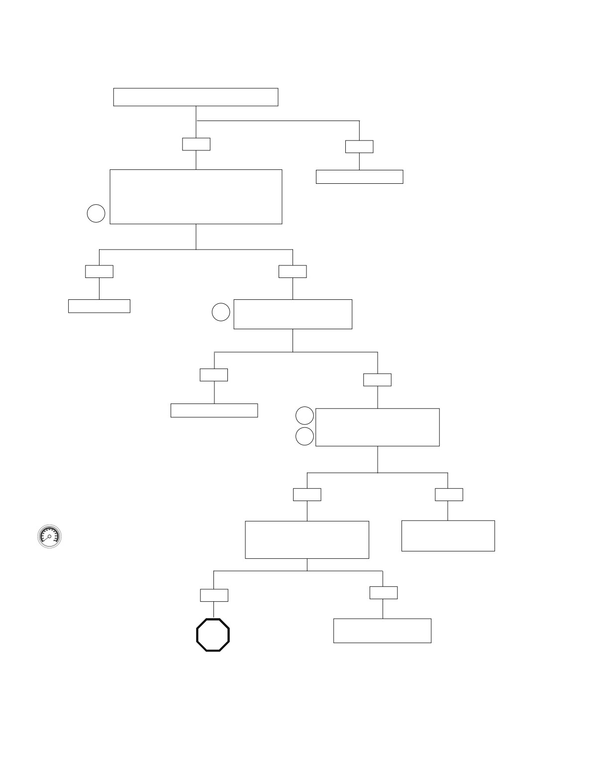
HOME
Test 5.25 (Part 1 of 2)
VEHICLE SPEED SENSOR: DTC P0501, P0502
Inspect connector [65]. Is connector mated properly?
YES
NO
Remove and inspect speedometer sensor. Inspect for
Mate connector [65].
debris and clean if necessary. Place speedometer
into diagnostic mode and clear fault codes. Connect
all circuits and ride motorcycle for approximately 1.0
mile (1.6 km). Check for speedometer function.
1
Speedometer functioning properly?
YES
NO
System OK.
Check for continuity between terminal
2
A of connector [65B] (R/W wire) and
ground. Continuity present?
YES
NO
Repair short to ground.
Check for continuity between terminal A
2
of connector [65B] (R/W wire) and ter-
minal 14 of breakout box. Continuity
3
present?
YES
NO
Clear codes using speedometer self diagnostics.
Check for continuity between terminal C
Locate and repair open on
See 5.6 SPEEDOMETER SELF DIAGNOSTICS.
of connector [65B] (BK wire) and
R/W wire between [78B]
Confirm proper operation with no check engine
ground. Continuity present?
and [65B].
lamp.
YES
NO
Repair open on Black wire
STOP
between [65B] and ground.
Go to. Test 5.25
(Part 2 of 2)
5-96
2004 Touring: Engine Management (EFI)
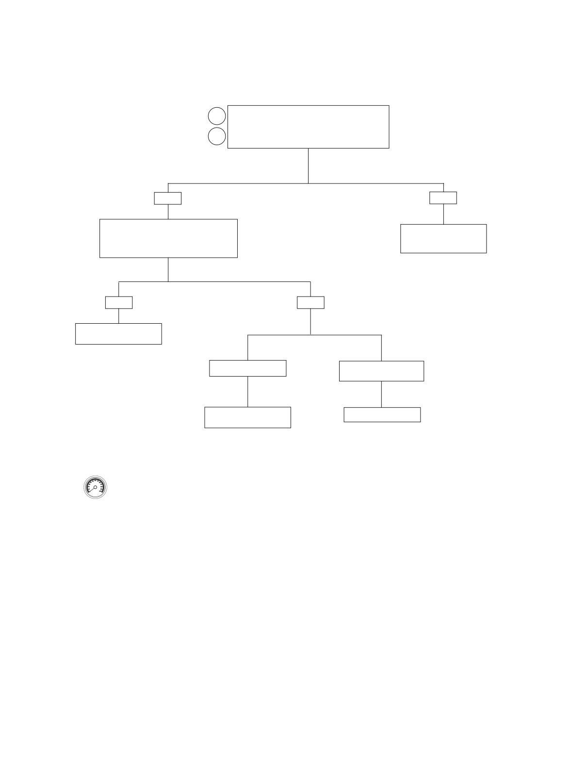
HOME
Test 5.25 (Part 2 of 2)
VEHICLE SPEED SENSOR: DTC P0501, P0502
Continued from Test 5.25 (Part 1 of 2).
2
Check for continuity between terminal B of connector
[65B] and terminal 33 of breakout box. Continuity
3
present?
YES
NO
Check for voltage on W/GN wire of connector
[65B] while connected. Meter should read 4-6
Locate and repair open on
W/GN wire between [78B]
volts when gear tooth absent and 0-1 volts
when gear tooth is present. Does it?
and [65B].
YES
NO
Replace ECM. Reprogram
and learn password.
4-6 volts not present.
4-6 volts present but no
fluctuation from 0-1 volts.
Replace ECM. Reprogram
Replace speed sensor.
and learn password.
Clear codes using speedometer self diagnostics.
See 5.6 SPEEDOMETER SELF DIAGNOSTICS.
Confirm proper operation with no check engine
lamp.
2004 Touring: Engine Management (EFI)
5-97
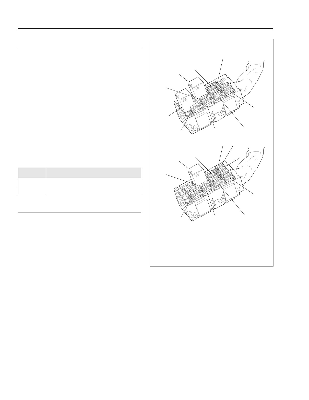
HOME
DTC P0562, P0563
5.26
GENERAL
System Fuse Block (Under Left Side Cover)
8
Battery Voltage
FLHR/C/S
Battery voltage is monitored by the ECM (terminal 13). If the
9
10
battery voltage fails to meet normal operating parameters, a
code is set.
5
11
● Code P0562 is displayed when battery positive voltage is
less than 11.0 volts at 2000 RPM for longer than 5 sec-
onds.
● Code P0563 is displayed when battery positive voltage is
4
greater than 16.0 volts for more than 4 seconds.
12
NOTES
● Warm idle speed will be automatically increased if bat-
f2210x8x
3
1
2
tery voltage is low at idle.
● TSSM problems may also set a code P0562 or P0563.
8
7
FLTR, FLHT/C/U
9
6
10
Table 5-43. Code Description
5
DTC
DESCRIPTION
11
P0562
Battery voltage low
P0563
Battery voltage high
4
DIAGNOSTICS
f2204x8x
2
3
1
Diagnostic Tips
1.
Headlamp
7.
Radio Power
● Low voltage generally indicates a loose wire, corroded
2.
Ignition
8.
Accessory
connections, battery and/or a charging system problem.
3.
Lighting
9.
Battery
4.
Instruments
10.
Brake Light Relay
● A high voltage condition may be caused by a faulty volt-
5.
Brakes/Cruise
11.
P&A
age regulator.
6.
Radio Memory
12.
Starter Relay
Figure 5-60. Fuse Locations
Diagnostic Notes
The reference numbers below correlate with the circled num-
bers on the Test 5.26 flow charts.
4. This checks for voltage drops in the ECM circuit.
1.
Was battery allowed to discharge? Was battery drawn
a. Place (+) probe to battery positive terminal.
down by a starting problem?
b. Place (-) probe to W/BK terminal on Breakout Box.
a. Yes. Charge battery.
b. No. See charging system troubleshooting.
5. Problem is most likely the ground connection at the
2.
Connect BREAKOUT BOX
(Part No. HD-43876)
frame.
between wire harness and ECM. See 5.7 BREAKOUT
6. Connect BREAKOUT BOX (Part No. HD-42682) to Con-
BOX: EFI.
nector [22]. FLHR/C/S models will also need HD-42962
3.
Use DVOM with RPM Pick-up to check RPM on vehicles
adapters.
without tachometers.
5-98
2004 Touring: Engine Management (EFI)
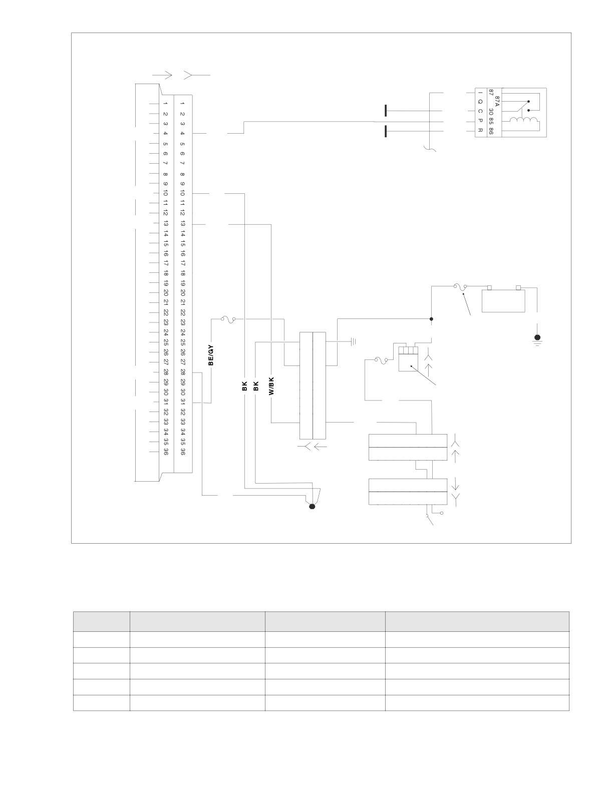
HOME
f2208k8x
[78A]
[78B]
[62B]
Y/GN
BE/GY
GN/O
System relay
GN/O
W/BK
System relay
Power gnd.
BK
Switch power
W/BK
ECM
+
-
15 amp
Battery
ECM fuse
BK
40 Amp
R
Maxi Fuse
R/BK
12
12
11
11
DCBA
10
10
[33B]
9
9
Power gnd.
15 amp
[33A]
8
8
7
7
IGN fuse
Ignition
6
6
5
5
GY
switch
Constant power
4
4
3
3
2
2
W/BK
1
1
12 11 10 9 8 7 6 5 4 3
21
[1B]
12 11 10 9 8 7 6 5 4 3
21
[1A]
[8B] [8A]
12 11 10 9 8 7 6 5 4 3
2
1
[22A]
BK
12 11 10 9 8 7 6 5 4 3
2
1
[22B]
Engine stop
switch
Figure 5-61. Battery Voltage Circuit (FLTR, FLHT/C/U)
Table 5-44. Wire Harness Connectors in Figure 5-61.
NO.
DESCRIPTION
TYPE
LOCATION
[1]
Main to Interconnect Harness
12-Place Deutsch (Black)
Inner Fairing (Right Fairing Bracket)
[8]
Main to EFI Harness
12-Place Deutsch (Gray)
Under Right Side Cover
[22]
Right Handlebar Switches
12-Place Deutsch (Black)
Inner Fairing (Right Fairing Support Brace)
[33]
Ignition/Light Key Switch
4-Place Packard
Inner Fairing (Top Fork Bracket)
[78]
ECM
36-Place Packard
Under Right Side Cover
2004 Touring: Engine Management (EFI)
5-99
HOME
f2208j8x
[62B]
Y/GN
[78A]
[78B]
BE/GY
GN/O
W/BK
System relay
System relay
GN/O
Power gnd.
BK
Switch power
W/BK
40 Amp
ECM
Maxi Fuse
+
-
15 amp
Battery
ECM fuse
BK
R
R/BK
12
12
11
11
I B A
10
10
[33B]
9
9
15 amp
[33A]
Power gnd.
8
8
IGN fuse
7
7
6
6
Ignition
5
5
GY
Constant power
switch
4
4
3
3
2
2
W/BK
1
1
12 11 10 9 8 7
6543
2
1
[22A]
[22B]
12 11 10 9 8 7
6543
2
1
[8B] [8A]
12-Place on
FLHP Only
Engine stop
BK
switch
Figure 5-62. Battery Voltage Circuit (FLHR/C/S)
Table 5-45. Wire Harness Connectors in Figure 5-62.
NO.
DESCRIPTION
TYPE
LOCATION
[8]
Main to EFI Harness
12-Place Deutsch (Gray)
Under Right Side Cover
[22]
Right Handlebar Switches
12-Place Deutsch (Black)
Inside Headlamp Nacelle
[33]
Ignition/Light Key Switch
3-Place Packard
Under Console
[78]
ECM
36-Place Packard
Under Right Side Cover
5-100
2004 Touring: Engine Management (EFI)
HOME
Test 5.26 (Part 1 of 2)
BATTERY VOLTAGE: DTC P0562, P0563
Perform charging system tests.
1
Charging system OK?
YES
NO
Connect Breakout Box. Measure voltage on
Repair charging system.
2
Breakout Box between terminal 13 (+) and
See Section 1.
terminal 10 (-) and again between terminal
13 and terminal 28 (-) with engine running at
3
2000 RPM or higher for 10 seconds or
longer. Is voltage above 11.0 volts?
YES
NO
System
With ignition ON, measure voltage drop
1
4
OK.
between battery positive (+) terminal
and Breakout Box terminal 13 (-).
Is voltage drop greater
than 0.5 volt?
YES
NO
With ignition ON, measure voltage drop
Check for voltage drop between battery
between battery positive (+) terminal
negative (-) terminal and terminal 10 (+)
and connector [22A] terminal 4 (-) (black). Is
on Breakout Box connector and between
voltage drop greater than 0.5 volt?
battery negative (-) terminal and terminal 28
on
Breakout Box. Is voltage drop greater than
0.5 volt?
YES
NO
With ignition ON, measure voltage drop
Replace W/BK
YES
NO
between battery positive (+) terminal
wire between
and connector [22A] terminal 3 (-). Is voltage
[22A] and [78B] or
drop greater than 0.5 volt?
terminals.
Locate and repair
Problem is intermittent.
bad connection.
Perform 5.8 WIGGLE
TEST. Locate and
repair bad connection.
5
YES
NO
Inspect [22] for corrosion or
loose wires. If above conditions
STOP
are not present, replace engine
stop switch.
Clear codes using speedometer self diagnostics.
See 5.6 SPEEDOMETER SELF DIAGNOSTICS.
Go to Test 5.26 (Part 2 of 2).
Confirm proper operation with no check engine
lamp.
2004 Touring: Engine Management (EFI)
5-101
HOME
Test 5.26 (Part 2 of 2)
BATTERY VOLTAGE: DTC P0562, P0563
Continued from Test 5.26 (Part 1 of 2).
With ignition ON, measure voltage drop between bat-
tery positive (+) terminal and GY terminal on 15 amp
ignition fuse (-). Is voltage drop greater than 0.5 volt?
YES
NO
With ignition ON, measure voltage drop
Replace GY wire
between battery positive (+) terminal and
or terminals.
R/BK terminal at 15 amp ignition fuse. Is
voltage drop greater than 0.5 volt?
YES
NO
With ignition ON, measure voltage drop
Replace fuse or
between battery positive (+) and both fuse
fuse terminals.
terminals (-).
Is voltage drop greater than 0.5 volt?
YES
NO
With ignition ON, measure voltage drop
Replace ignition
between battery positive (+) terminal and
switch or terminals.
one fuse terminal (-).
Is voltage drop greater than 0.5 volt?
YES
NO
High resistance between
Replace maxi fuse.
maxi fuse and battery. Replace
wire or terminals.
Clear codes using speedometer self diagnostics.
See 5.6 SPEEDOMETER SELF DIAGNOSTICS.
Confirm proper operation with no check engine
lamp.
5-102
2004 Touring: Engine Management (EFI)
HOME
DTC P0603, P0605
5.27
GENERAL
DIAGNOSTICS
NOTE
ECM Failure
These codes are set under two conditions.
● If DTC P0603 or P0605 occur during normal operation,
Refer to Table 5-46. The codes listed indicate a failure which
replace ECM. Reprogram and learn password.
requires replacement of the ECM. See the Touring Service
Manual for replacement information.
● If DTC P0603 or P0605 occur during or after reprogram-
ming, perform the following:
NOTE
DTC P0603
After replacing ECM, perform password learning procedure
1. Clear codes.
and clear codes.
2. Power down the vehicle. Wait 10 seconds.
3. Turn ignition ON,
Table 5-46. Code Description
4. Replace ECM if codes reappear.
DTC
DESCRIPTION
DTC P0605
P0603
ECM EEPROM error
1. Clear codes.
P0605
ECM flash error
2. Power down the vehicle.
3. Attempt to reprogram ECM using correct calibration.
4. Restart vehicle. If code reappears, replace ECM.
2004 Touring: Engine Management (EFI)
5-103