Harley Davidson 2004 Touring Models. Service Manual - page 12
HOME
[62B]
CKP
To Tachometer
Y/GN
[78]
(FLHR/C/S Optional)
System
relay
BE/GY
[79A]
1
2
GN/O
[79B]
1
2
3
W/BK
R
30
15 Amp
fuel pump
[13A] [13B]
BK
12
fuse
System relay
4
GN/O
Fuel
O/GY
pump
Y/GN
Inj. F
21
W/Y
[141B] [141A]
[84B]
[84A]
BK
Y/GN
All Except
FLHR/C/S
[83B]
[83A]
Inj. R
19
GN/GY
[85B]
[85A]
Coil
Ion sense
27
GY/BE
Coil R
11
Y/BE
Coil F
29
BE/O
A
A
BE/GN
35
40 Amp
B
B
BN/R
36
Maxi fuse
C
C
BK/PK
18
+
-
D
D
BK/O
17
15 Amp
Battery
ECM fuse
R
[87A]
[87B]
Constant
31
BE/GY
Intake air
power
BK
control
Engine
stop
15 Amp
switch
IGN fuse
Switch power
13
W/BK
GY
R/BK
Ignition switch
BK/W
TP
R/W
sensor
TP sensor
24
GY/V
GY/V
To right
[90B] [90A]
hand controls
[88B] [88A]
ET sensor
6
PK/Y
ET sensor
GY
BK/W
W/BK
W/BN
IAT sensor
7
LT GN/Y
IAT sensor
5v sensor gnd.
26
BK/W
BK/W
[22A]
[89B] [89A]
[80B] [80A]
BK/W
MAP sensor
V/W
V/W
MAP
25
sensor
5v sensor pwr.
14
R/W
R/W
Vehicle
Vehicle speed sensor
W/GN
speed
33
sensor
[65B] [65A]
Serial data
5
LT GN/V
To speedometer
and tachometer
[91A]
3
Data link
1
connector
2
Flash pin
1
LT GN/R
4
[30B]
2
3
7
TSM/
Power gnd.
10
BK
TSSM
[30A]
2
3
7
Power gnd.
28
BK
f2208g8x
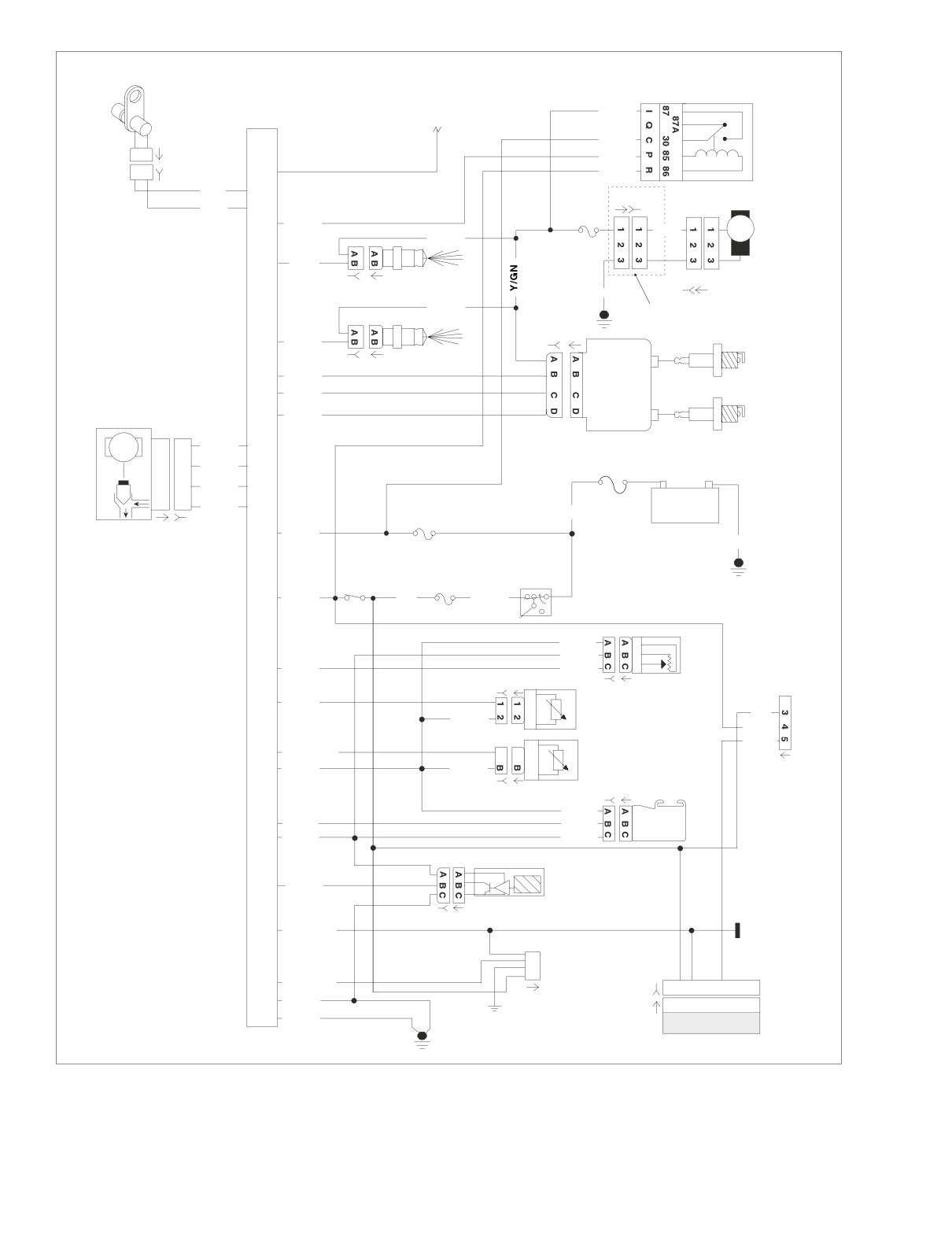
Figure 5-2. EFI System Circuit - Simplified
5-4
2004 Touring: Engine Management (EFI)
HOME
EFI DIAGNOSTIC INTRODUCTION
5.3
SYSTEM PROBLEMS
All system problems fall into at least one of three general cat-
egories.
60
40
50
70
30
50
40
80
No Start
30
90
20
MPH
RPM x100
20
100
The engine cranks over freely, but will not start. This does not
10
10
110
include situations where the engine will not crank, such as a
security disabled starter, dead battery, etc. This condition
0
120
0
assumes that all obvious checks (fuel in tank, etc.) have been
made.
TI
-D
-D
Poor Performance
The engine starts but there are performance problems. These
problems may include poor fuel economy, rough idle, engine
Check Engine Lamp
misfire, engine hesitation, severe spark knock, etc.
f2160x8x
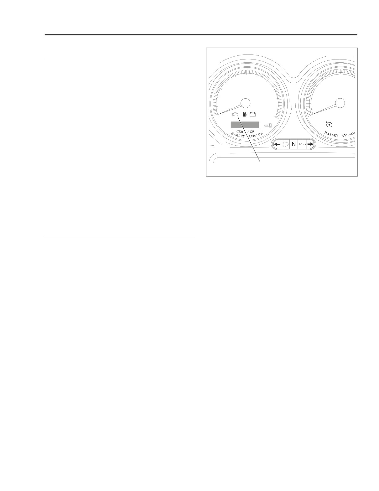
Figure 5-3. Speedometer
Check Engine Lamp
See Figure 5-3. The check engine lamp indicates the ECM
has determined a fault condition exists. There may also be
starting or performance problems.
RESOLVING PROBLEMS
To resolve system problems, five basic steps are involved. In
order of occurrence, they are:
1.
Check for diagnostic trouble codes by using speedome-
ter self diagnostics. See 5.4 CHECKING FOR DIAG-
NOSTIC TROUBLE CODES: EFI.
2.
Retrieve diagnostic trouble codes by using speedometer
self diagnostics. See 5.6 SPEEDOMETER SELF DIAG-
NOSTICS.
3.
Diagnose system problems. This involves using special
tools and the diagnostic flow charts in this section.
4.
Correct problems through the replacement and/or repair
of the affected components.
5.
After repairs are performed, the work must be validated.
This involves clearing the trouble codes and confirming
proper vehicle operation as indicated by the lack of trou-
ble codes.
2004 Touring: Engine Management (EFI)
5-5
HOME
CHECKING FOR DIAGNOSTIC TROUBLE CODES: EFI
5.4
CHECK ENGINE LAMP
To diagnose system problems, start by observing the behav-
ior of the check engine lamp.
NOTES
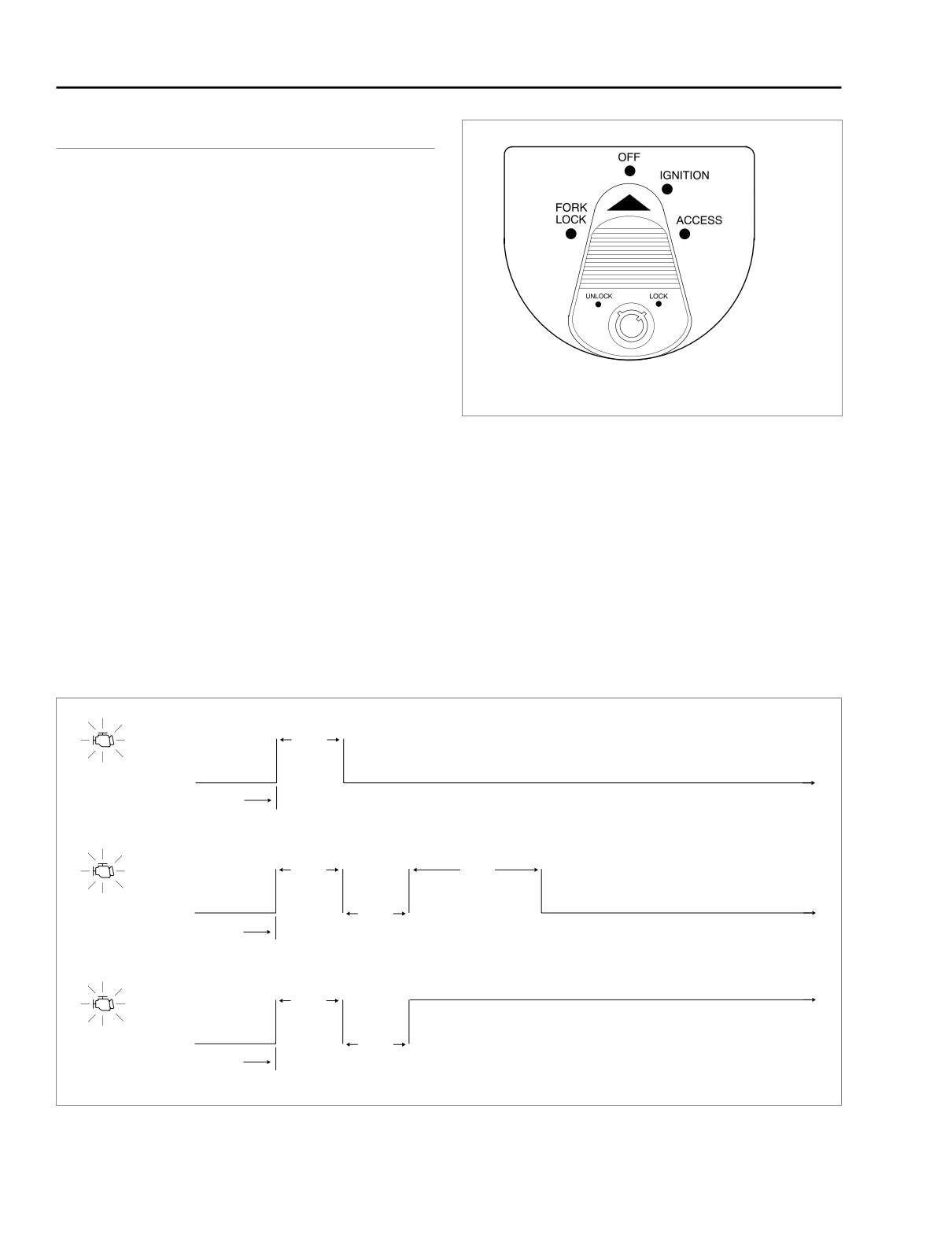
● See Figure 5-4. “Key ON” means that the ignition key is
turned to IGN and the engine stop switch is set to RUN
(although the engine is not running).
● When the ignition key is turned ON, the check engine
lamp will illuminate for approximately four seconds and
then turn off.
f1240x2x
● If the check engine lamp is not illuminated at Key ON or if
it fails to turn OFF after the initial four second period,
then the speedometer may need to be replaced. See 5.5
Figure 5-4. Ignition Switch (FLTR, FLHT/C/U)
INITIAL DIAGNOSTIC CHECK: EFI.
1. When the lamp turns off after being illuminated for the
2.
See CODE TYPES which follows for a complete descrip-
first four second period, it will:
tion of trouble code formats.
a. Remain off if there are no fault conditions or trouble
NOTE
codes currently detected by the ignition control mod-
Some trouble codes can only be fully diagnosed during actu-
ule. See A of Figure 5-5.
ation. For example, a problem with the ignition coil will be
b. Come back on for an 8 second period if only historic
considered a current fault even after the problem is corrected,
codes exist. See B of Figure 5-5.
since the ECM will not know of its resolution until after the coil
is exercised by vehicle start sequence. In this manner, there
c. Come back on, and remain on, if a current trouble
may sometimes be a false indication of the current trouble
code exists. See C of Figure 5-5.
code.
ON
4 Sec.
A
Lamp OFF: No Current or Historic Trouble Codes
OFF
Key On
Lamp ON 8 Seconds:
Only Historic Trouble Codes Exist
ON
4 Sec.
8 Sec.
B
Lamp OFF
OFF
4 Sec.
Key On
Lamp Remains ON: Current Trouble Code *
ON
4 Sec.
C
OFF
4 Sec.
* Historic Trouble Codes May Also Exist
Key On
Figure 5-5. Check Engine Lamp Operation
5-6
2004 Touring: Engine Management (EFI)
HOME
CODE TYPES
RETRIEVING DIAGNOSTIC
TROUBLE CODES
There are two types of diagnostic trouble codes (DTCs): cur-
rent and historic. If a diagnostic trouble code is stored, it can
be read using speedometer self diagnostics. See
5.6
The engine management system provides two levels of diag-
SPEEDOMETER SELF DIAGNOSTICS.
nostics.
All diagnostic trouble codes reside in the memory of the
● The most sophisticated mode uses a computer based
ECM/ICM, TSM/TSSM, speedometer or tachometer until the
diagnostic package called the DIGITAL TECHNICIAN
code is cleared by use of the speedometer self diagnostics.
(Part No. HD-44750).
See 5.6 SPEEDOMETER SELF DIAGNOSTICS.
● The second mode requires using the speedometer self
A historic diagnostic trouble code is also cleared after a total
diagnostics. Speedometer, tachometer
(if equipped),
of 50 trips has elapsed. A trip consists of a start and run
TSM/TSSM and ECM codes can be accessed and
cycle. After the 50 trip retention period, the diagnostic trouble
cleared. See 5.6 SPEEDOMETER SELF DIAGNOSTICS
code is automatically erased from memory providing that no
for more information.
subsequent faults of the same type are detected in that
period.
MULTIPLE DIAGNOSTIC TROUBLE
Current
CODES
Current trouble codes are those which occur during the
present ignition cycle. See the appropriate flow charts for
solutions.
While it is possible for more than one fault to occur and set
more than one trouble code, there are several conditions
Historic
which may result in one fault setting multiple trouble codes:
If a particular problem happens to resolve itself, the active
● The MAP and TP and vehicle speed sensors are con-
status problem is dropped and it becomes a historic code
nected to the same reference line (+5V Vref). If the refer-
rather current code.
ence line goes to ground or open, multiple codes will be
Historic codes are stored for a length of time to assist in the
set (DTC P0107, P0122 and P0501).
diagnosis of intermittent faults. See Figure 5-5. The check
● Serial data codes (DTC U1300, U1301, U1016, U1064,
engine lamp will come back on for 8 seconds to indicate the
U1097 and U1255) may be accompanied by other
existence of only historic codes.
codes. Always correct the serial data codes before
It is important to note that historic codes may also be present
resolving the other codes.
whenever the system indicates the existence of a current
Refer to Table 5-5. This table gives most ECM DTCs a priority
code. See MULTIPLE DIAGNOSTIC TROUBLE CODES if
multiple trouble codes are found.
ranking.
Diagnostic charts are designed for use with current trouble
codes and as a result they frequently suggest part replace-
ment. When diagnosing a historic code the charts can be
helpful but should not lead to part replacement without verifi-
cation the part is faulty.
2004 Touring: Engine Management (EFI)
5-7
HOME
INITIAL DIAGNOSTIC CHECK: EFI
5.5
GENERAL
Diagnostic Tips
● If speedometer reads “No Rsp” (no response) while in
To locate faulty circuits or other system problems, follow the
diagnostic mode, check data bus for an open or short to
diagnostic flow charts in this section. For a systematic
ground between data connector [91A] Terminal 3 and
approach, always begin with INITIAL DIAGNOSTICS which
ECM, TSM/TSSM, tachometer (if equipped) or speedom-
follows. Read the general information and then work your way
eter. For more information on speedometer diagnostic
through the flow chart box by box.
mode see 5.6 SPEEDOMETER SELF DIAGNOSTICS.
Diagnostic Notes
● Check for an open diagnostic test terminal between data
Terminal 3 and ECM Terminal 5. With ignition key turned
If a numbered circle appears adjacent to a flow chart box,
ON, transmit data should be typically 0.6-0.8 volts. The
then more information is offered in the diagnostic notes. Many
range of acceptable voltage is greater than 0 and less
diagnostic notes contain supplemental information, descrip-
than 7.0 volts.
tions of various diagnostic tools or references to other parts
● If speedometer reads “BUS er” (serial data bus error),
of the manual where information on the location and removal
refer to flow charts in 5.12 STARTS, THEN STALLS.
of components may be obtained.
Diagnostic Notes
Circuit Diagram/Wire Harness
Connector Table
The reference numbers below correlate with the circled num-
bers on the diagnostic check flow charts. See page 5-15.
When working through a flow chart, refer to the illustrations,
the associated circuit diagram and the wire harness connec-
1.
Compare engine behavior to symptoms tables.
tor table as necessary. The wire harness connector table for
each circuit diagram identifies the connector number, descrip-
a. Starts hard. Refer to Table 5-2.
tion, type and general location.
b. Hesitates, stumbles, surges, misfires and/or slug-
In order to perform most diagnostic routines, a Breakout Box
gish performance. Refer to Table 5-3.
and a DVOM are required. See 5.7 BREAKOUT BOX: EFI.
c. Engine exhaust emits black smoke or fouls plugs.
Refer to Table 5-4.
To perform the circuit checks with any degree of efficiency, a
familiarity with the various wire connectors is also necessary.
2.
Connect BREAKOUT BOX (Part No. HD-43682) to
speedometer using HD-46601 adapters.
Reprogramming ECM
All EFI diagnostic codes are listed on page 5-11 in Table 5-5.
Diagnostic charts frequently suggest ECM replacement. In
the event an electronic control module (ECM) needs to be
Other Codes
replaced, it must be reprogrammed using a computer based
diagnostic package called DIGITAL TECHNICIAN (Part No.
See 3.9 INITIAL DIAGNOSTIC CHECK: TSM/TSSM for any
HD-44750). See your dealer. Password learn procedure must
codes related to the turn signal module (TSM) or turn signal
also be performed. See 3.24 PASSWORD LEARN.
security module (TSSM).
See 2.2 INITIAL DIAGNOSTIC CHECK: SPEEDOMETER for
any codes related to the speedometer or tachometer.
INITIAL DIAGNOSTICS
General Information
The diagnostic check
(see page
5-15) is an organized
approach to identifying a problem caused by an electronic
control system malfunction.
5-8
2004 Touring: Engine Management (EFI)
HOME
Table 5-1. Typical Scan Values for
Table 5-2. Engine Starts Hard
Engine Data
SYMPTOM
SOLUTION
MIN.
MAX.
HOT
ITEM
See charging system trouble-
VALUE
VALUE
IDLE
Battery discharged
shooting in this section.
10.3-13.3 in. Hg
10 kPa
104 kPa
5.17 MISFIRE AT IDLE OR
35-45 kPa
Spark plugs
MAP sensor
UNDER LOAD.
0 volts
5.1 volts
5.17 MISFIRE AT IDLE OR
Spark plug wires
0
100
0%
UNDER LOAD.
TP sensor
0.2 volts
4.5 volts
0.2-1.0 volts
5.17 MISFIRE AT IDLE OR
Ignition coil
UNDER LOAD.
IAC pintle
0
155
30-45 steps
See Section 3 in the Touring
RPM
800
5600
990
Valve sticking
Service Manual.
3° F
464° F
230-300° F
Water or dirt in fuel system
Drain and refill with fresh fuel.
(-16° C)
(240° C)
(110-150° C)
ET sensor
Loss of battery power to
0.0 volts
5.0 volts
0.5-3.23 volts
5.11 NO ECM POWER
ECM terminal 31*
3° F
248° F
104-140° F
IAT sensor
(-16° C)
(120° C)
(40-60° C)
* Codes will not clear (although they appear to).
0.0 volts
5.0 volts
2.0-3.5 volts
INJ PW front
0
50 mS
2-4 mSec
INJ PW rear
0
50 mS
2-4 mSec
Advance front
0
45°
10-15°
Advance rear
0
45°
10-15°
VSS
0
120
0 MPH
Battery voltage
10
15
14.5 volts
ENG RUN
off
Run
Run
Idle RPM
800
1250
990
NOTE
Hot idle specifications are with stock exhaust, the engine
operating at 990 RPM and an engine temperature of approxi-
mately 260° F (127° C). Idle settings may be changed with
the idle set procedure. See the Touring Service Manual.
2004 Touring: Engine Management (EFI)
5-9
HOME
Table 5-3. Engine Performance Problems
Table 5-4. Engine Exhaust Emits
Black Smoke or Fouls Plugs
SYMPTOM
SOLUTION
SYMPTOM
SOLUTION
Manifold leak
See
5.9 INTAKE LEAK
See AIR CLEANER FILTER
TEST.
Clogged air filter
in the Touring Service Man-
NOTE- When manifold leak
is large enough, IAC will
A low IAC count may also
ual.
close to 0 and code P0505
indicate an air leak.
MAP sensor plugged or not
5.19 DTC P0107, P0108.
will set
operating properly
MAP sensor plugged or not
5.19 DTC P0107, P0108.
operating properly
Drain and refill with fresh
Water or dirt in fuel system
fuel.
5.17 MISFIRE AT IDLE OR
Spark plugs
UNDER LOAD.
See throttle cable adjust-
Throttle plate not opening
ment in the Touring Service
fully
Manual.
5.15 FUEL PRESSURE
Low fuel pressure
TEST.
5-10
2004 Touring: Engine Management (EFI)

HOME
Table 5-5. EFI Diagnostic Trouble Codes (DTC) and Fault Conditions
PRIORITY
DTC NO.
FAULT CONDITION
SOLUTION
RANKING
1
P0605
ECM flash error
5.27 DTC P0603, P0605
2
P0603
ECM EEPROM error
5.27 DTC P0603, P0605
3
“BUS Er”
Serial data bus shorted low/open/high
5.12 STARTS, THEN STALLS
4
U1300
ECM serial data low
5.12 STARTS, THEN STALLS
5
U1301
ECM serial data open/high
5.12 STARTS, THEN STALLS
6
U1300
TSSM serial data low
5.12 STARTS, THEN STALLS
7
U1301
TSSM serial data open/high
5.12 STARTS, THEN STALLS
8
U1300
Speedometer/tachometer serial data low
5.12 STARTS, THEN STALLS
Speedometer/tachometer serial data open/
9
U1301
5.12 STARTS, THEN STALLS
high
10
U1064
Loss of TSM/TSSM serial data at ECM
5.30 DTC U1064, U1255
Loss of TSM/TSSM serial data at speedome-
11
U1064
5.30 DTC U1064, U1255
ter
Loss of all ECM serial data (state of health) at
3.21 DTC U1016, U1255
TSSM
Loss of all ECM serial data (state of health) at
3.21 DTC U1016, U1255
12
U1016
speedometer
Loss of vehicle speed
3.21 DTC U1016, U1255
Loss of vehicle inhibit motion
3.21 DTC U1016, U1255
Loss of powertrain security status
3.21 DTC U1016, U1255
13
U1097
Loss of speedometer serial data at TSSM
5.31 DTC U1097, U1255
14
U1255
Missing response at TSSM
3.21 DTC U1016, U1255
15
U1255
Missing response at speedometer
5.31 DTC U1097, U1255
16
P1003
System relay contacts open
5.14 SYSTEM RELAY CHECK
17
P1002
System relay coil high/shorted
5.14 SYSTEM RELAY CHECK
18
P1001
System relay coil open/low
5.14 SYSTEM RELAY CHECK
19
P1004
System relay contacts closed
5.14 SYSTEM RELAY CHECK
20
P1009
Incorrect password
5.28 DTC P1009, P1010
21
P1010
Missing password (starts then stalls)
5.28 DTC P1009, P1010
22
P0373
CKP sensor intermittent
5.24 DTC P0373, P0374
23
P0374
CKP sensor synch error
5.24 DTC P0373, P0374
24
P0122
TP sensor open/low
5.22 DTC P0122, P0123
25
P0123
TP sensor high
5.22 DTC P0122, P0123
26
P0107
MAP sensor open/low
5.19 DTC P0107, P0108
27
P0108
MAP sensor high
5.19 DTC P0107, P0108
28
P0117
ET sensor voltage low
5.21 DTC P0117, P0118
29
P0118
ET sensor open/high
5.21 DTC P0117, P0118
30
P0112
IAT sensor voltage low
5.20 DTC P0112, P0113
31
P0113
IAT sensor open/high
5.20 DTC P0112, P0113
32
P1351
Front ignition coil open/low
5.29 DTC P1351, P1352, P1354, P1355
33
P1354
Rear ignition coil open/low
5.29 DTC P1351, P1352, P1354, P1355
34
P1352
Front ignition coil high/shorted
5.29 DTC P1351, P1352, P1354, P1355
35
P1355
Rear ignition coil high/shorted
5.29 DTC P1351, P1352, P1354, P1355
36
P1357
Front cylinder combustion intermittent
5.18 COMBUSTION ABSENT/INTERMITTENT
37
P1358
Rear cylinder combustion intermittent
5.18 COMBUSTION ABSENT/INTERMITTENT
38
P0261
Front injector open/low
5.23 DTC P0261, P0262, P0263, P0264
39
P0263
Rear injector open/low
5.23 DTC P0261, P0262, P0263, P0264
40
P0262
Front injector high
5.23 DTC P0261, P0262, P0263, P0264
2004 Touring: Engine Management (EFI)
5-11
HOME
Table 5-5. EFI Diagnostic Trouble Codes (DTC) and Fault Conditions
PRIORITY
DTC NO.
FAULT CONDITION
SOLUTION
RANKING
41
P0264
Rear injector high
5.23 DTC P0261, P0262, P0263, P0264
42
P0562
Battery voltage low
5.26 DTC P0562, P0563
43
P0563
Battery voltage high
5.26 DTC P0562, P0563
44
P0501
VSS sensor low
5.25 DTC P0501, P0502
45
P0502
VSS sensor high
5.25 DTC P0501, P0502
46
P1356
Rear cylinder no combustion
5.18 COMBUSTION ABSENT/INTERMITTENT
47
P1353
Front cylinder no combustion
5.18 COMBUSTION ABSENT/INTERMITTENT
48
P0505
Loss of idle speed control
5.16 IDLE AIR CONTROL
49
B1135
Accelerometer fault
3.19 DTC B1135
51
B1134
Starter output high
3.18 DTC B1134
52
B1121
Left turn output fault
3.15 TURN SIGNAL ERRORS
53
B1122
Right turn output fault
3.15 TURN SIGNAL ERRORS
54
B0563
Battery voltage high
3.16 DTC B0563
55
B1131
Alarm output low
3.17 DTC B1131, B1132
56
B1132
Alarm output high
3.17 DTC B1131, B1132
57
B1141
Ignition switch open/low
3.15 TURN SIGNAL ERRORS
5-12
2004 Touring: Engine Management (EFI)
HOME
[156B] [156A]
f2208u8x
Main to Interconnect
6
6
5
5
Harness
4
4
BK
3
3
GY
2
2
BK
LtGN/V
1
1
LtGN/V
O
1
2
3
4 5 6 7 8 9 10 11 12
[30B]
BN/GY
1
2
3
4 5 6 7 8 9 10 11 12
[30A]
BN/GY
TSM/TSSM
BK
[39B]
1
2
3
4 5 6 7 8 9 10 11 12
GY
1
2
3
4 5 6 7 8 9 10 11 12
[39A]
Speedometer
1
2
3
4 5 6 7 8 9 10 11 12
1
2
3
4 5 6 7 8 9 10 11 12
[8B]
EFI
[108B]
1
2
3
4 5 6 7 8 9 10 11 12
1
2
3
4 5 6 7 8 9 10 11 12
[8A]
Harness
[108A]
Tachometer
[1B] [1A]
15A
1
Accessory
Fuse
2
Main to Interconnect
3
Harness
1
2
3
4 5 6 7 8 9 10 11 12
4
[2B]
Data Link
1
2
3
4 5 6 7 8 9 10 11 12
15A
[2A]
Ignition
Main to Interconnect
Fuse
[91A]
Harness
[78B]
15A
1
5
ECM
Battery
[78A]
Fuse
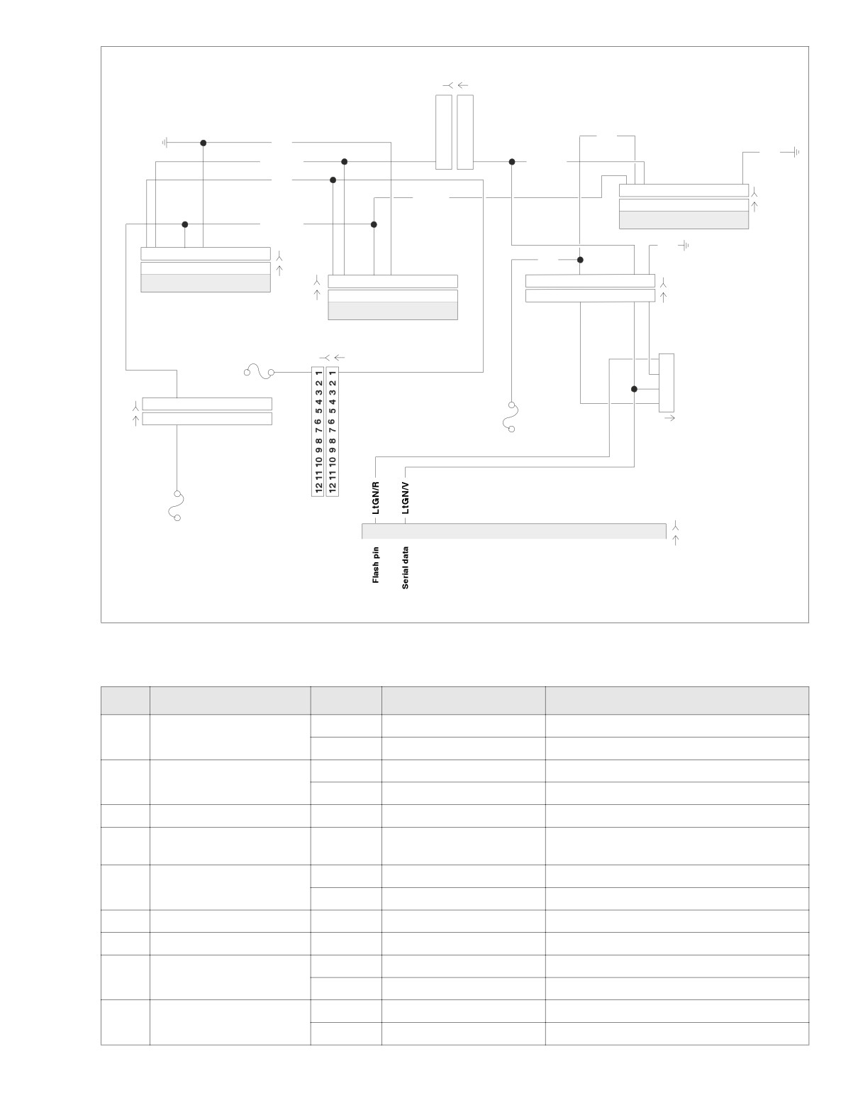
Figure 5-6. Diagnostic Check (FLTR, FLHT/C/U)
Table 5-6. Wire Harness Connectors in Figure 5-6.
NO.
DESCRIPTION
MODEL
TYPE
LOCATION
Main to Interconnect
FLHT/C
12-Place Deutsch (Black)
Inner Fairing - Right Radio Support Bracket
[1]
Harness
FLTR
12-Place Deutsch (Black)
Inner Fairing - Below Radio (Left Side)
Main to Interconnect
FLHT/C
12-Place Deutsch (Gray)
Inner Fairing - Right Fairing Support Brace
[2]
Harness
FLTR
12-Place Deutsch (Gray)
Inner Fairing - Below Radio (Left Side)
[8]
Main to EFI Harness
All
12-Place Deutsch (Gray)
Under Right Side Cover
Turn Signal/Security
Cavity in Crossmember at Rear of
[30]
All
12-Place Deutsch
Module
Battery Box (Under Seat)
FLHT/C
12-Place Packard
Inner Fairing (Back of Speedometer)
[39]
Speedometer
FLTR
12-Place Packard
Under Bezel (Back of Speedometer)
[78]
Electronic Control Module
All
36-Place Packard
Under Right Side Cover
[91]
Data Link
All
4-Place Deutsch
Under Right Side Cover
FLHT/C
12-Place Packard
Inner Fairing (Back of Tachometer)
[108]
Tachometer
FLTR
12-Place Packard
Under Bezel (Back of Tachometer)
Main to Interconnect
FLHT/C
6-Place Deutsch
Inner Fairing - Right Fairing Support Brace
[156]
Harness
FLTR
6-Place Deutsch
Inner Fairing - Front of Right Fairing Bracket
2004 Touring: Engine Management (EFI)
5-13
HOME
f2208t8x
BK
GY
LtGN/V
LtGN/V
BK
BN/GY
O
1
2
3
4 5 6 7 8 9 10 11 12
[30B]
1
2
3
4 5 6 7 8 9 10 11 12
[30A]
BN/GY
TSM/TSSM
BK
1
2
3
4 5 6 7 8 9 10 11 12
[39B]
1
2
3
4 5 6 7 8 9 10 11 12
[39A]
GY
Speedometer
1
2
3
4
5
6
7
8 9 10 11 12
[8B]
EFI
1
2
3
4
5
6
7
8 9 10 11 12
[8A]
Harness
15A
15A
Accessory
Battery
Fuse
Fuse
1
15A
2
Ignition
3
Fuse
4
Data Link
[91A]
[78B]
1
5
ECM
[78A]
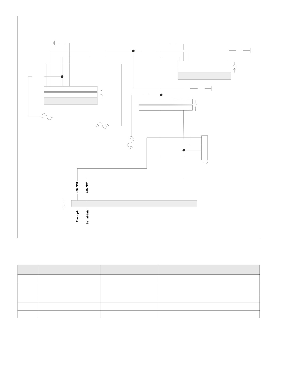
Figure 5-7. Diagnostic Check (FLHR/C/S)
Table 5-7. Wire Harness Connectors in Figure 5-7.
NO.
DESCRIPTION
TYPE
LOCATION
[8]
Main to EFI Harness
12-Place Deutsch
Under Right Side Cover
Cavity in Crossmember at Rear of
[30]
Turn Signal/Security Module
12-Place Deutsch
Battery Box (Under Seat)
[39]
Speedometer
12-Place Packard
Under Console (Back of Speedometer)
[78]
Electronic Control Module
36-Place Packard
Under Right Side Cover
[91]
Data Link
4-Place Deutsch
Under Right Side Cover
5-14
2004 Touring: Engine Management (EFI)
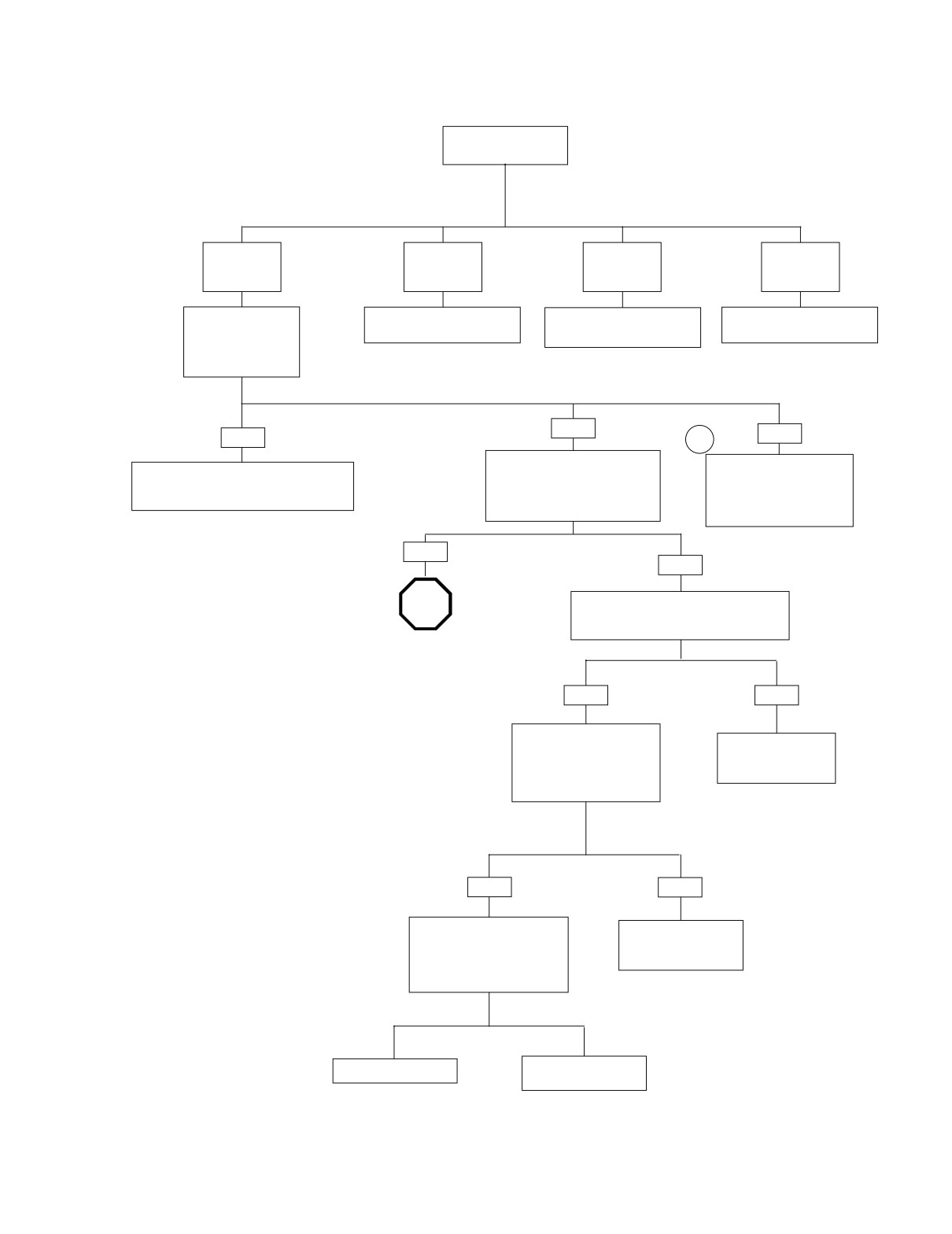
HOME
Diagnostic Check (Part 1 of 2)
Does engine
start?
YES.
YES.
NO.
NO.
Starts and
Starts, then
Cranks, but
Engine will not
runs.
stalls.
will not start.
crank.
Check for trouble
See 5.12 STARTS, THEN
See 5.10 ENGINE CRANKS,
See 1.2 STARTING SYSTEM
codes. See 5.6
STALLS.
BUT WILL NOT START.
DIAGNOSIS.
SPEEDOMETER
SELF DIAGNOSTICS
Codes found?
NO
NO
YES
1
Unable to enter diagnostic mode.
No codes displayed. For
Refer to applicable trouble code priority chart.
With ignition switch OFF, press and
symptoms that may not set
All diagnostic codes are listed on page 5-11
release odometer reset switch.
diagnostic trouble codes,
in Table 5-5. Codes are listed by priority.
Does odometer display appear with
refer to table 5-2, Table 5-3
display backlighting?
and Table 5-4.
YES
NO
STOP
Check for continuity to ground on terminal 7
of speedometer. Wiggle harness during con-
tinuity check. Continuity present?
Go to Diagnostic
Check (Part 2 of 2).
YES
NO
Check for battery voltage at
terminal 5 of speedometer
Locate and repair open
while wiggling harness. Bat-
between terminal 7
tery voltage continuously
and ground.
present?
YES
NO
Check continuity (with ignition
Locate and repair open
switch OFF) between terminals
between terminal 5 and
8 and 11 on breakout box. Con-
battery fuse.
tinuity present when speedome-
ter reset switch is depressed?
Replace speedometer.
Replace speedometer
reset switch.
2004 Touring: Engine Management (EFI)
5-15
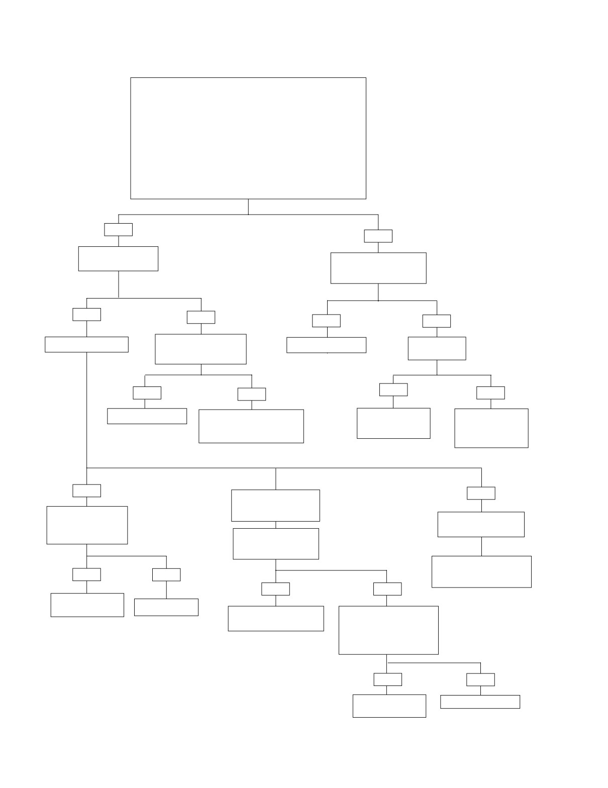
HOME
Diagnostic Check (Part 2 of 2)
Continued from Diagnostic Check (Part 1 of 2).
Perform “wow” test. See 5.6 SPEEDOMETER SELF DIAGNOSTICS.
The following features should be functional
1) backlight should illuminate
2) needle should sweep its full range of motion
3) LED’s that should illuminate:
• check engine
• battery
• security (all models)
4) LED’s that may illuminate:
• low fuel (EFI models)
• cruise (even though not cruise equipped)
Are all features functional?
YES
NO
Turn key to ACC. Is
backlight present?
Check for battery voltage at
terminal 1 of breakout box.
Battery voltage present?
YES
NO
YES
NO
Is problem intermittent?
Check for battery voltage at
Replace speedometer.
Is instrument
breakout box terminal 6.
fuse blown?
Battery voltage present?
YES
YES
NO
NO
Replace speedometer.
Locate and repair open on O/W
Locate and repair
Locate and repair
wire between terminal 6 of con-
source of fault.
open between terminal
nector [39] and accessory fuse.
Replace fuse.
1 of connector [39]
and instrument fuse.
YES
NO
YES
Intermittent vehicle speed
Repeat Diagnostic
indication.
Check while wiggling
Tachometer Inoperative
(no engine speed).
harnesses. Intermittent
present?
Remove and inspect vehi-
cle speed sensor. Debris
present?
See Test 2.4 (Part 1 of 2)
under 2.4 SPEEDOMETER/
YES
NO
TACHOMETER.
YES
NO
Locate and repair
intermittent.
No trouble found.
Remove debris. Reinstall
Check for damaged wiring/
vehicle speed sensor.
loose connection between
vehicle speed sensor and
ECM. Is wiring damage/loose
connection present?
YES
NO
Locate and repair
Replace Speedometer.
source of fault.
5-16
2004 Touring: Engine Management (EFI)
HOME
SPEEDOMETER SELF DIAGNOSTICS
5.6
GENERAL
d0715x8x
The speedometer is capable of displaying and clearing
speedometer, tachometer, TSM/TSSM, and ICM/ECM trouble
codes (diagnostic mode).
DIAGNOSTICS
Diagnostic Tips
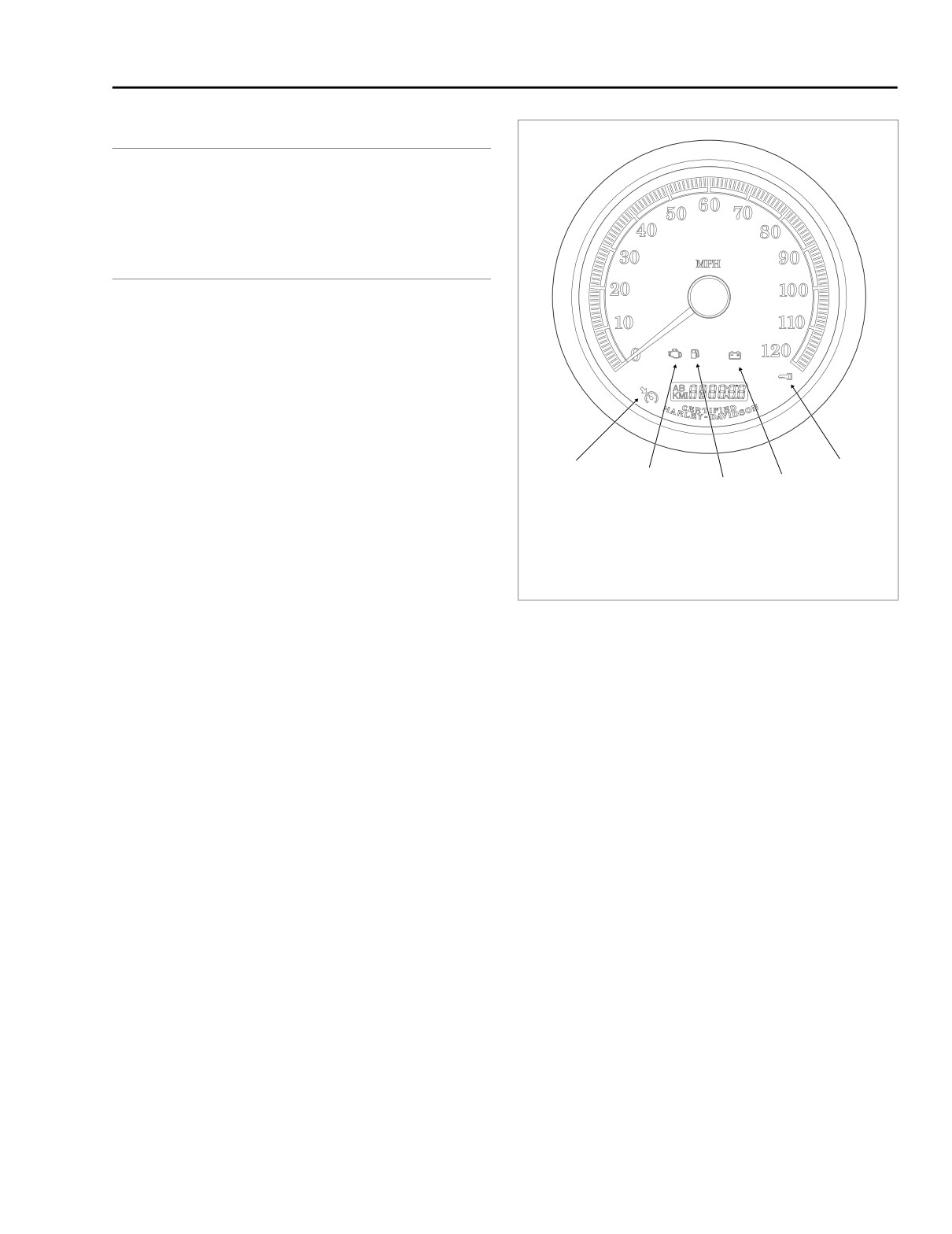
● For a quick check of speedometer function, a “wow” test
can be performed. See Figure 5-8. Press and hold
odometer reset switch then turn ignition switch ON.
Release reset switch. Background lighting should illumi-
nate, speedometer needle should sweep its full range of
motion, and indicator lamps [battery, security, low fuel
(EFI models) check engine and cruise] should illuminate.
1
5
Some lamps may illuminate even though they do not
2
apply to the vehicle. For example, the cruise lamp may
3
4
illuminate even though the motorcycle may not be
equipped with cruise control.
1.
Cruise On/Engaged
4. Battery
● If instrument module fails “wow” test, check for battery,
2.
Check Engine
5. Security
ground, ignition, speedometer reset switch and acces-
3.
Low Fuel
sory to speedometer. If any feature in the speedometer is
non-functional, see 2.2 INITIAL DIAGNOSTIC CHECK:
Figure 5-8. Speedometer (FLHR/C/S)
SPEEDOMETER.
Diagnostic Notes
Use of speedometer self diagnostics assumes that DIGITAL
TECHNICIAN (Part No. HD-44750) is not available.
The reference numbers below correlate with the circled num-
bers in the Speedometer Self Diagnostics (chart)
1.
To exit diagnostic mode, turn ignition switch OFF.
2.
To clear DTCs for selected module, press speedometer
reset switch for more than 5 seconds when code is dis-
played. This procedure will clear all codes for selected
module.
2004 Touring: Engine Management (EFI)
5-17
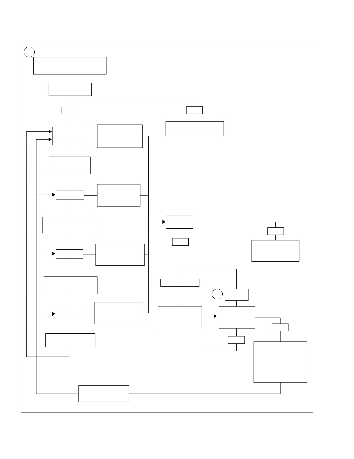
HOME
Speedometer Self Diagnostics (chart)
1
While holding odometer reset switch in,
turn ignition switch to IGN. Make sure
Run/Stop switch is in RUN position.
Release reset switch.
Does “diag” appear?
YES
NO
See 2.2 INITIAL DIAGNOSTIC
To display DTCs for the
CHECK: SPEEDOMETER.
ECM, press and hold
”P” flashing.
reset switch for more
than 5 seconds.
To choose TSM/
TSSM, press and
release reset switch.
To display DTCs for
”S” flashing.
TSM/TSSM, press and
hold reset switch for
more than 5 seconds.
To
choose Speedometer,
Device
response?
press and release reset
switch.
NO
YES
“no rsp” displayed.*
To display DTCs for
Tachometer malfunction.
”SP” flashing.
speedometer, press and
See 2.4 SPEEDOMETER/
hold reset switch for more
TACHOMETER.
than 5 seconds.
Models not equipped
*
with a tachometer will
display “no rsp” nor-
To choose Tachometer,
mally.
“none” displayed.
press and release reset
switch.
DTC
2
displayed.
To display DTCs for
tachometer, press and
Press and release
Press and release
”T” flashing.
hold reset switch for more
reset switch. Part num-
reset switch.
than 5 seconds.
ber of module will be
Are more DTCs
displayed.
displayed?
NO
To choose ECM, press
YES
and release reset switch.
“end” displayed.
To clear all DTCs for
selected module hold reset
switch for more than 5 sec-
onds. If DTCs are not to be
cleared, Press and release
reset switch. Part number of
module will be displayed.
Press and release reset
switch again to continue to
next module.
Figure 5-9. Speedometer Self Diagnostics
5-18
2004 Touring: Engine Management (EFI)
HOME
BREAKOUT BOX: EFI
5.7
GENERAL
f1917x9x
The BREAKOUT BOX (Part No. HD-43876) splices into the
main harness. Used in conjunction with a DVOM, it allows cir-
cuit diagnosis of wiring harness and connections without hav-
ing to probe with sharp objects.
NOTE
See wiring diagrams for ECM terminal functions.
INSTALLATION
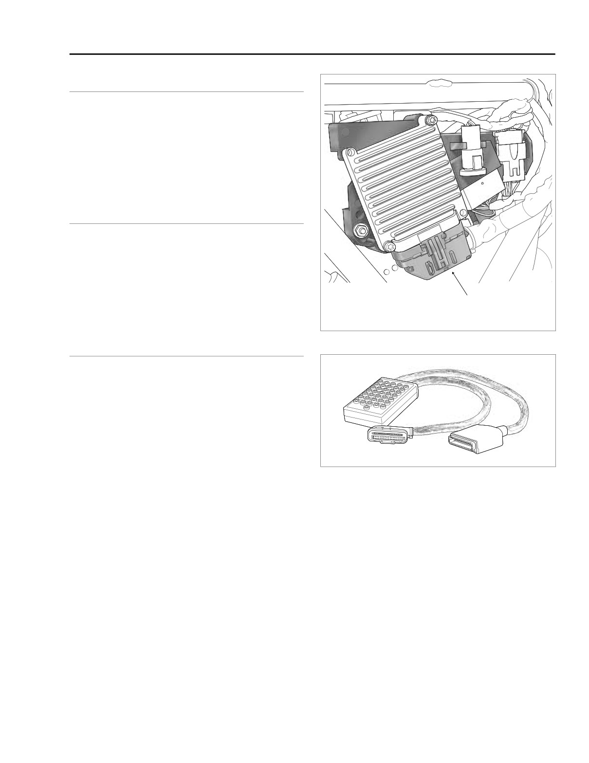
1. Remove right saddlebag and side cover. See Figure 5-
10.
2. Depress latch and remove connector [78B] to release
EFI harness from ECM.
3. Install connectors on Breakout Box to ECM and EFI har-
Electronic Control
Module Connector [78]
ness connectors.
Figure 5-10. Electrical Bracket (Under Right Side Cover)
REMOVAL
1. Separate connectors to remove Breakout Box between
ECM and EFI harness.
2. Install connector [78B] to connect EFI harness to ECM.
3. Install right side cover and saddlebag.
Figure 5-11. Breakout Box (Part No. HD-43876)
2004 Touring: Engine Management (EFI)
5-19
HOME
WIGGLE TEST
5.8
GENERAL
hd39978
The wiggle test indicates the presence of intermittents in a
wiring harness.
PROCEDURE
1.
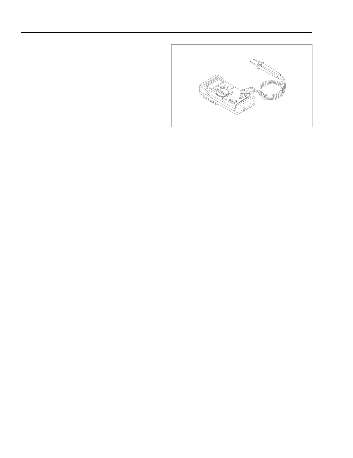
See Figure 5-12. Connect DVOM (Part No. HD-39978) to
wiring harness between the suspect connections. When
diagnosing ECM connections, use a BREAKOUT BOX
(Part No. HD-43876) to simplify the procedure. See 5.7
BREAKOUT BOX: EFI.
Figure 5-12. Fluke 78 Multimeter (DVOM)
(Part No. HD-39978)
2. Set DVOM to read voltage changes.
3. Start motorcycle engine and run at idle.
4. Shake or wiggle harness to detect intermittents. If inter-
mittents are present, radical voltage changes will register
on the DVOM.
5-20
2004 Touring: Engine Management (EFI)
HOME
INTAKE LEAK TEST
5.9
GENERAL
9648
1DANGER
Propane is an extremely flammable liquid and vapor.
Vapor may cause flash fire. Keep away from heat, sparks
and flame. Keep container closed. Use only with ade-
quate ventilation.
1WARNING
Read all directions and warnings on propane bottle. Fail-
ure to follow all directions and warnings on bottle could
result in death or serious injury.
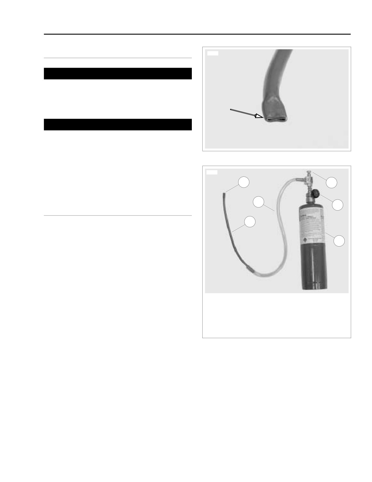
Figure 5-13. Nozzle
● To prevent false readings, keep airbox cover installed
when performing test.
9649
● Do not direct propane into air cleaner, false readings will
1
4
result.
3
5
LEAK TESTER
2
Parts List
6
● Standard 14 oz. propane cylinder.
● Snap-on YA7148 Propane Enrichment Kit.
●
12 in. (304 mm) long-1/4 in. (6 mm) diameter copper tub-
ing.
Tester Assembly
1.
Nozzle
1. Cut rubber hose from kit to 18 in. (457 mm) in length.
2.
Copper tube
3.
Hose
2.
See Figure 5-13. Flatten one end of copper tube to form
4.
Valve
a nozzle.
5.
Knob
3. Insert round side of copper tube into end of tubing.
6.
Propane bottle
Figure 5-14. Leak Tester
2004 Touring: Engine Management (EFI)
5-21
HOME
INTAKE LEAK TESTING
10054
1. Start engine.
2. Warm engine to operating temperature.
3. See Figure 5-14. Turn knob (5) counterclockwise to open
propane bottle (6).
1DANGER
Propane is an extremely flammable liquid and vapor.
Vapor may cause flash fire. Keep away from heat, sparks
and flame. Keep container closed. Use only with ade-
quate ventilation.
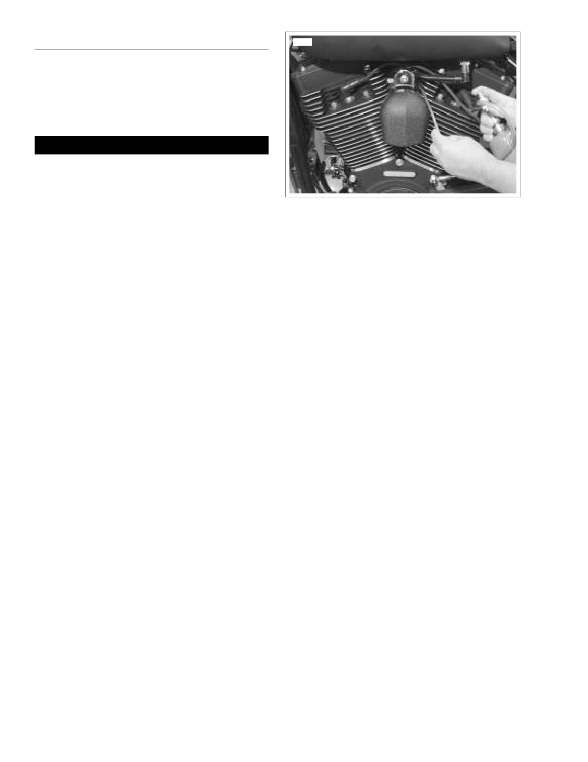
Figure 5-15. Checking for Leaks
NOTE
Do not direct propane stream toward front of engine. If pro-
pane enters air cleaner, a false reading will be obtained.
4. See Figure 5-15. Aim nozzle toward possible sources of
leak such as fuel injectors and intake tract.
5. See Figure 5-14. Push valve (4) to release propane.
Tone of engine will change when propane enters source
of leak.
5-22
2004 Touring: Engine Management (EFI)
HOME
ENGINE CRANKS, BUT WILL NOT START
5.10
GENERAL
d0273x8x
If the starter will not crank the engine, the problem is not EFI
related. Refer to SECTION 1-STARTING & CHARGING or
SECTION 3-TSM & TSSM.
DIAGNOSTICS
Diagnostic Notes
The reference numbers below correlate with the circled num-
bers on the Test 5.10 flow charts.
Figure 5-16. Spark Tester
1. Check for trouble codes. See RETRIEVING DIAGNOS-
TIC TROUBLE CODES under 5.4 CHECKING FOR
DIAGNOSTIC TROUBLE CODES: EFI.
7863
2.
Check the condition of the battery. Perform a voltage test
and recharge if below 12.60V. Check battery connections
and perform load test. Replace the battery if necessary.
See BATTERY in the Touring Service Manual.
3. Connect BREAKOUT BOX (Part No. HD-43876). See 5.7
BREAKOUT BOX: EFI.
4.
Remove spark plug cable from spark plug.
a. Visually check condition of plug.
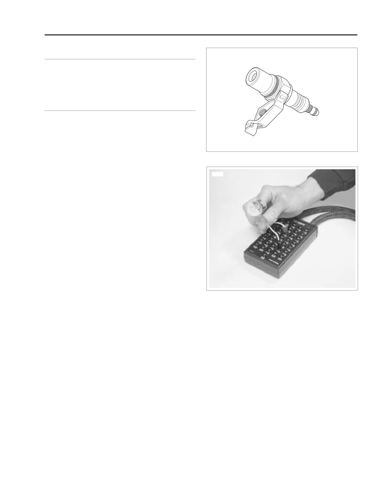
b. See Figure 5-16. Attach cable to SPARK TESTER
(Part No. HD-26792). Clip tester to cylinder head
bolt.
c. While cranking engine, look for spark. Repeat pro-
cedure on other spark plug cables.
Figure 5-17. Ignition Coil Circuit Test
NOTE
Engine will not spark with both spark plugs removed. When
checking for spark, use SPARK TESTER (Part No. HD-
26792) with both plugs installed.
Diagnostic Tips
5. Use HARNESS CONNECTOR TEST KIT (Part No. HD-
Check TP sensor value with DVOM. If TP sensor is equal to or
41404), gray pin probe and patch cord.
greater than 3.8 volts, system is in “clear flood” mode and
engine will not start. While spark is present, fuel is shut off.
6.
Typically, when IAC is not functioning, the engine will not
Problem can be mechanical, such as throttle cables stuck.
start unless throttle is opened and the engine will stall
when throttle is closed.
7. See Figure 5-17. Plug IGNITION COIL CIRCUIT TEST
ADAPTER (Part No. HD-44687) and FUEL INJECTOR
TEST LAMP (Part No. HD-34730-2C) into Breakout Box
Terminals 13 and 11. Start engine. If lamp flashes, no
problem is found. Repeat for Breakout Box Terminals 13
and 29.
8. Use HARNESS CONNECTOR TEST KIT (Part No. HD-
41404), brown socket probe and patch cord.
2004 Touring: Engine Management (EFI)
5-23