Harley Davidson 2006 Sportster XLH MODELS. Service Manual - page 32
HOME
x0522a3x
BK
LtGN/V
O
LtGN/V
O/W
BN/GY
GY
BK
Odometer
reset switch
BN/GY
1
2
3
4 5 6 7 8 9 10 11 12
[39B]
[30B]
1
2
3
4 5 6 7 8 9 10 11 12
1
2
3
4 5 6 7 8 9 10 11 12
1
2
3
4 5 6 7 8 9 10 11 12
[39A]
[30A]
Speedometer
TSM/TSSM
[108B]
1
2
3
4 5 6 7 8 9 10 11
12
1
2
3
4 5 6 7 8 9 10 11
12
[108A]
Tachometer
[20B]
(if equipped)
1
2
3
4
5 67 8 9
10
11 12
[20A]
1
2
3
4
5 67 8 9
10
11 12
BK
15A
ACC
Data link
connector
BN/GY
15A
1
1
BATT
BK
2
2
LtGN/V
3
3
15A
INST
4
4
GY
15A
[91A]
[91B]
IGN
Fuse
block
LtGN/V
[10B]
1
2
3
4
5
6
7
8
9
10
11
12
[10A]
Ignition Control Module (ICM)
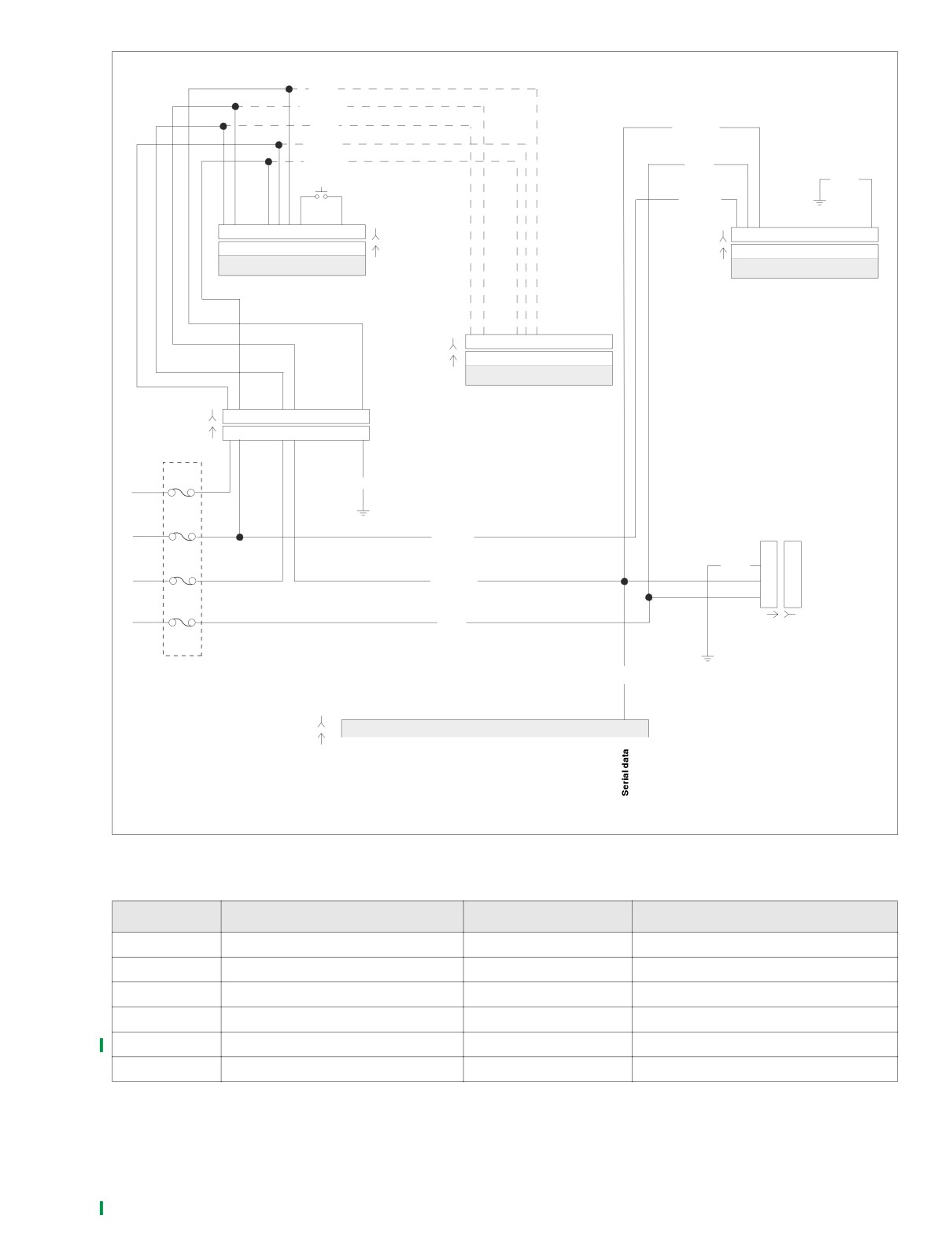
Figure 3-10. Serial Data Circuit
Table 3-11. Wire Harness Connectors in Figure 3-10.
NO.
DESCRIPTION
TYPE
LOCATION
[10]
Ignition control module
12-place Deutsch
under seat
[20]
Instruments
12-place Deutsch
under fuel tank
[30]
TSM/TSSM
12-place Deutsch
under battery
[39]
Speedometer
12-place Packard
back of speedometer
[91A]
Data link connector
4-place Deutsch
behind left side cover
[108]
Tachometer (if equipped)
12-place Packard
back of tachometer
2006 Sportster: TSM & TSSM
3-23
HOME
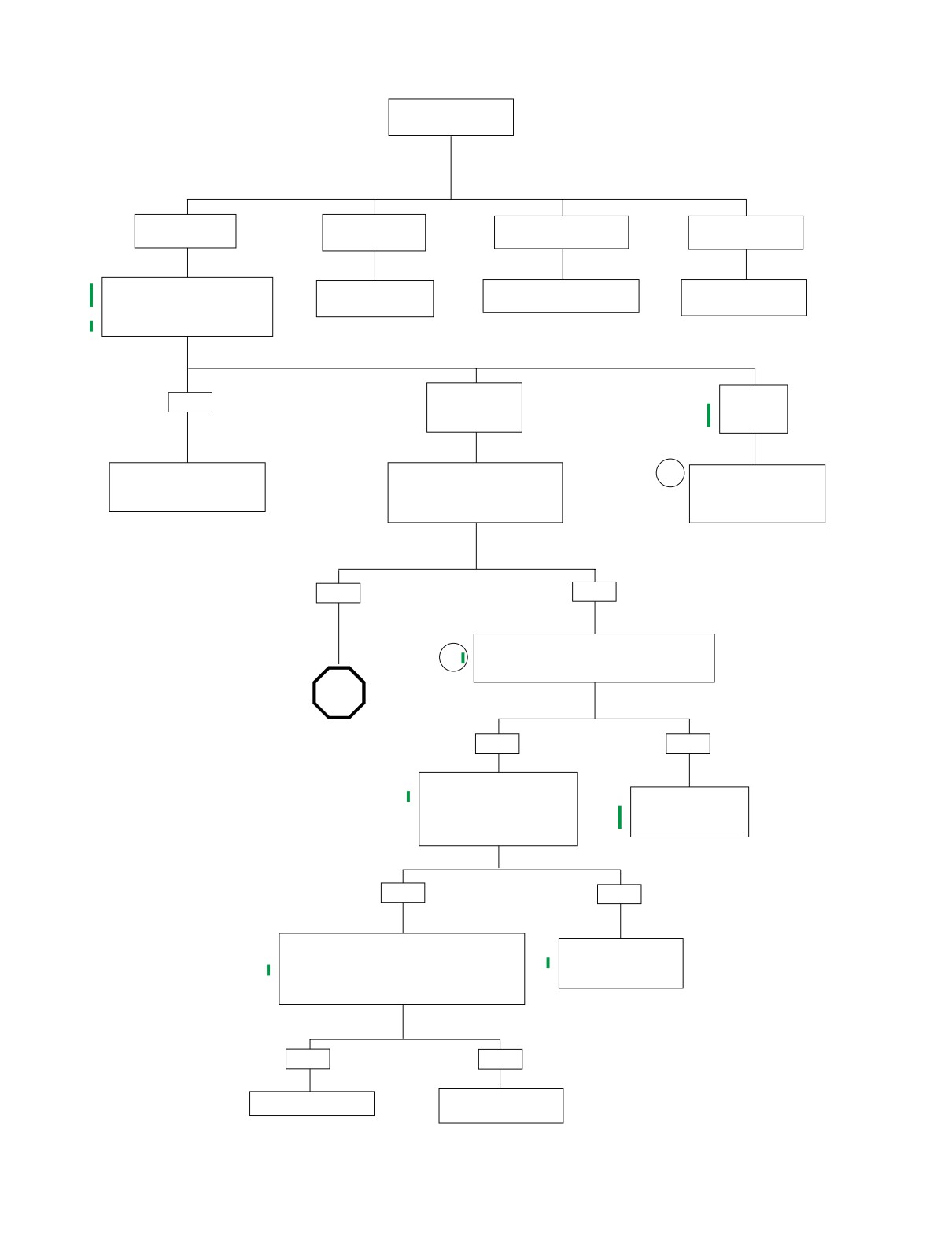
Initial Diagnostic Check (Part 1 of 3)
Does engine
start?
YES.
YES.
NO.
NO.
Starts and runs.
Starts, then stalls.
Cranks, but will not start.
Engine will not crank.
Check for diagnostic trouble codes
See 4.10 STARTS
See 4.9 ENGINE CRANKS
See 1.2 STARTING
(DTCs). See 3.10 SPEEDOME-
THEN STALLS.
BUT WILL NOT START.
SYSTEM DIAGNOSIS.
TER SELF DIAGNOSTICS
DTCs found?
NO
NO
YES
Unable to enter
No DTCs
diagnostic mode.
displayed.
Refer to applicable DTC priority
With ignition switch OFF, press and
2
For a list of symptoms that
chart. All DTCs are listed by
release odometer reset switch.
may not set diagnostic
priority in Table 3-9.
Does odometer display appear with
trouble codes, refer to
display backlighting?
Table 3-10.
YES
NO
Check for continuity to ground at breakout box
1
cavity 7 (black). Wiggle harness during continuity
check. Continuity present?
STOP
Go to Initial Diagnostic
Check (Part 2 of 3).
YES
NO
Check for battery voltage at
breakout box cavity 5
Locate and repair open
(black) of speedometer while
between cavity 7
wiggling harness. Battery volt-
and ground.
age continuously present?
YES
NO
With ignition switch OFF and speedometer
Locate and repair open
connector [39] disconnected, check continuity
between cavity 5 and
between Breakout Box cavities 8 and 11
battery fuse.
Is continuity present when speedometer reset
switch is depressed and infinity when released?
YES
NO
Replace Speedometer.
Replace speedometer
reset switch.
3-24
2006 Sportster: TSM & TSSM
HOME
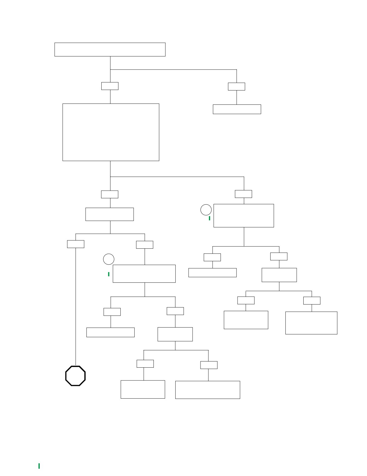
Initial Diagnostic Check (Part 2 of 3)
Continued from Initial Diagnostic Check (Part 1 of 3).
Turn ignition switch ON, is odometer backlight present?
YES
NO
Perform “wow” test.
Replace Speedometer.
See 3.10 SPEEDOMETER SELF DIAGNOSTICS.
The following features should be functional
1) backlight should illuminate
2) needle should sweep its full range of motion
3) LEDs should illuminate:
• check engine
• battery
• security (all models)
Are all features functional?
YES
NO
With ignition switch turned to
Turn key to ACC.
1
IGN, check for battery voltage
Is backlight present?
at cavity 1 of Breakout Box.
Battery voltage present?
YES
NO
YES
NO
1
Check for battery voltage at
Breakout Box cavity 6.
Replace Speedometer.
Is instrument
fuse blown?
Is battery voltage present?
YES
NO
YES
NO
Locate and repair
Locate and repair open
source of fault.
between terminal 1 of
Replace fuse.
connector [39] and
Replace Speedometer.
Is accessory
instrument fuse.
fuse blown?
YES
NO
STOP
Locate and repair
Locate and repair open on O/W
Go to Initial Diagnostic
source of fault.
wire between terminal 6 of con-
Check (Part 3 of 3).
Replace fuse.
nector [39] and accessory fuse.
2006 Sportster: TSM & TSSM
3-25
HOME
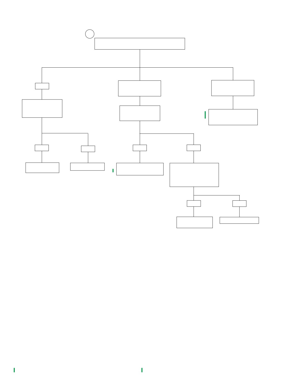
Initial Diagnostic Check (Part 3 of 3)
2
Continued from Initial Diagnostic Check (Part 2 of 3).
Is problem intermittent?
NO.
NO.
YES
Speedometer Inoperative
Tachometer Inoperative
(no vehicle speed).
(no engine speed).
Repeat Diagnostic
Check while wiggling
Remove and inspect
harnesses.
vehicle speed sensor.
See Test 2.4 (Part 1 of 2).
Was intermittent found?
Is debris present?
under 2.4 SPEEDOMETER/
TACHOMETER
YES
NO
YES
NO
Locate and repair
No trouble found.
Remove debris. Reinstall
Check for damaged wiring/
intermittent.
vehicle speed sensor.
loose connection between
vehicle speed sensor and ICM.
Is wiring damage/loose
connection present?
YES
NO
Locate and repair
Replace Speedometer.
source of fault.
3-26
2006 Sportster: TSM & TSSM
HOME
SPEEDOMETER SELF DIAGNOSTICS
3.10
GENERAL
10067
The speedometer is capable of displaying and clearing
speedometer, TSM/TSSM, and ICM diagnostic trouble codes
(DTCs) (diagnostic mode).
DIAGNOSTICS
Diagnostic Tips
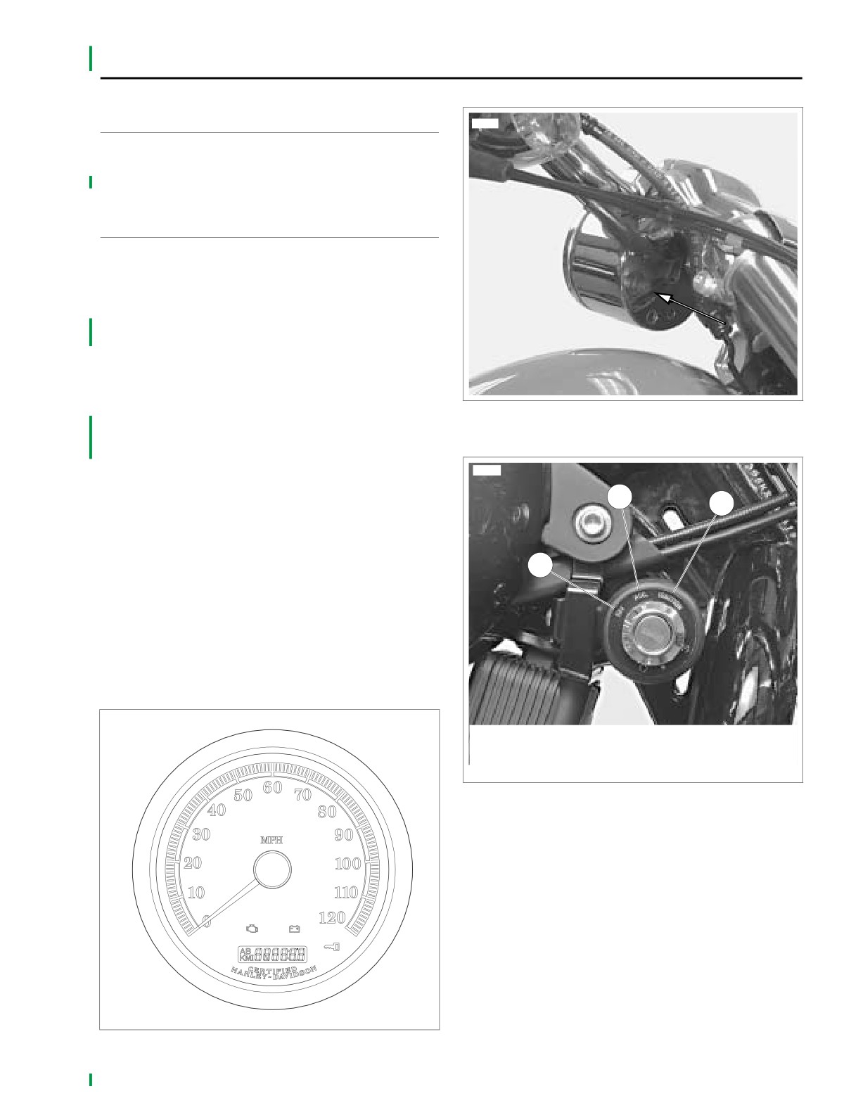
● For a quick check of speedometer function, a “wow” test
can be performed. See Figure 3-11. Figure 3-12. and
Figure 3-13. Press and hold odometer reset switch then
turn ignition switch to IGNITION. Release reset switch.
Background lighting should illuminate, gauge needles
should sweep their full range of motion, and indicator
lamps (battery, security and check engine) should illumi-
nate.
Figure 3-12. Odometer Reset Switch
● If speedometer fails “wow” test, check for battery, ground,
ignition, odometer reset switch and accessory wiring to
speedometer. If any feature in the speedometer is non-
functional, see
2.2 INITIAL DIAGNOSTIC CHECK:
11526
SPEEDOMETER.
2
3
Diagnostic Notes
Use of speedometer self diagnostics assumes that DIGITAL
TECHNICIAN (Part No. HD-44750) is not available.
1
The reference numbers below correlate with the circled num-
bers in Speedometer Self Diagnostics (chart).
1. To exit diagnostic mode, turn ignition switch OFF.
2. To clear DTCs for the selected module, press the odome-
ter reset switch for more than five seconds when DTC is
displayed. This procedure will clear all DTCs for the
selected module.
x0523x3x
1.
Ignition OFF
2.
ACC ON
3.
Ignition ON
Figure 3-13. Ignition Switch
Figure 3-11. Speedometer
2006 Sportster: TSM & TSSM
3-27
HOME
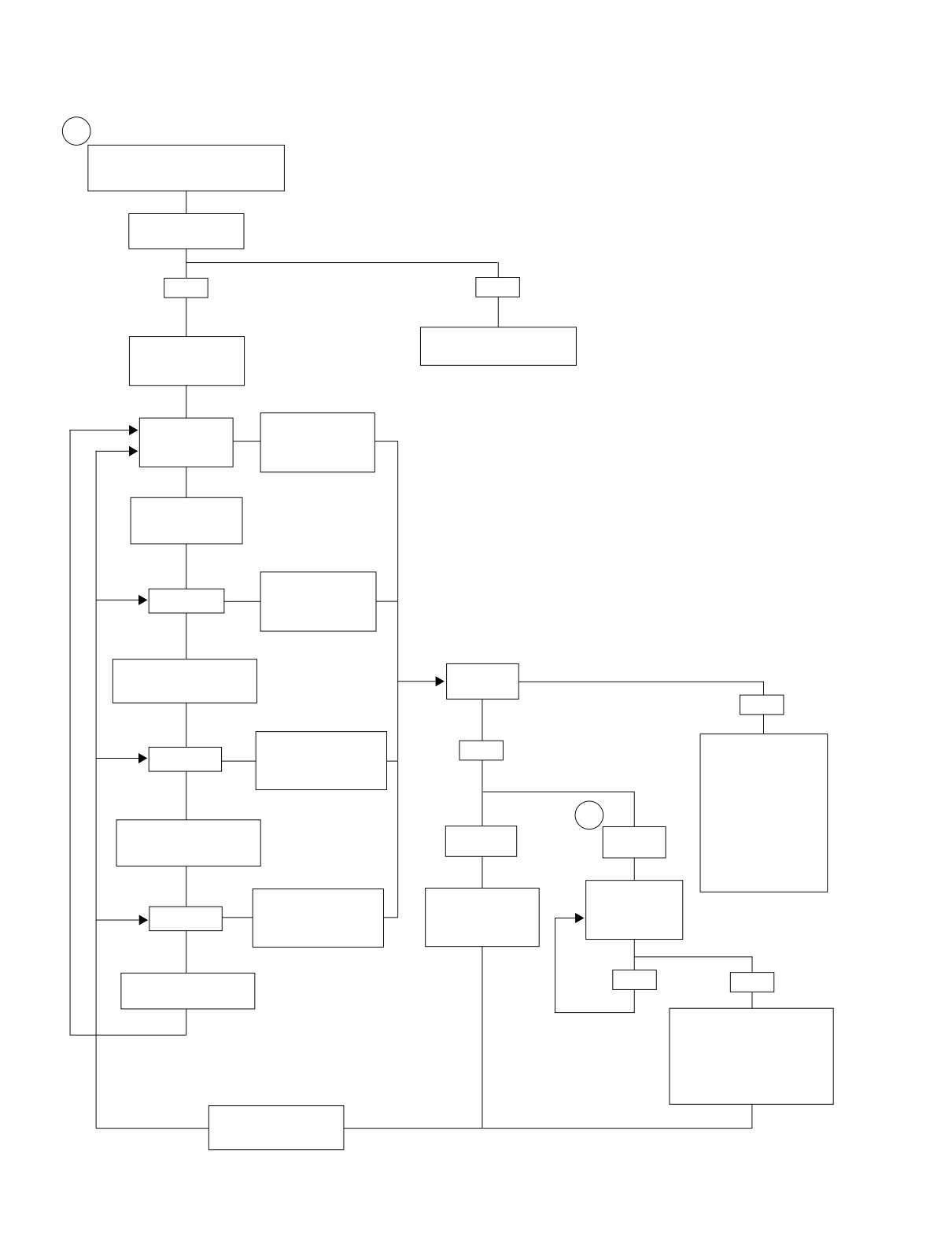
Speedometer Self Diagnostics (chart)
1
While holding odometer reset switch in,
turn ignition switch to IGN. Make sure
Run/Stop switch is in RUN position.
Release reset switch.
Does “diag” appear?
YES
NO
See 2.2 INITIAL DIAGNOSTIC
Press and release
CHECK: SPEEDOMETER
reset switch.
“PSSPT” appears.
To display DTCs for
the ICM, press and
”P” flashing.
hold reset switch for
more than 5 seconds.
To choose TSM/
TSSM, press and
release reset switch.
To display DTCs for
TSM/TSSM, press and
”S” flashing.
hold reset switch for
more than 5 seconds.
To
choose Speedometer,
Device
press and release reset
response?
switch.
NO
To display DTCs for
“no rsp” displayed.
speedometer, press and
YES
”SP” flashing.
See applicable code from
hold reset switch for more
other modules. Models
than 5 seconds.
not equipped with a
tachometer will display
“no rsp” normally.
2
To choose Tachometer,
If “no rsp” displayed on
“none”
DTC
press and release reset
odometer on tachometer
displayed.
displayed.
switch.
equipped vehicle,
see 2.4 SPEEDOMETER/
TACHOMETER.
Press and release
To display DTCs for
Press and release
reset switch.
tachometer, press and
reset switch. Part
”T” flashing.
Are more DTCs
hold reset switch for more
number of module will
displayed?
than 5 seconds.
be displayed.
To choose ICM, press and
YES
NO
release reset switch.
“end” displayed. To clear all
DTCs for selected module, hold
reset switch for more than 5
seconds. If DTCs are not to be
cleared, press and release reset
switch. Part number of module
will be displayed.
Press and release reset
switch again to continue to
next module.
3-28
2006 Sportster: TSM & TSSM
HOME
BREAKOUT BOX: TSM/TSSM
3.11
GENERAL
s0474x9x
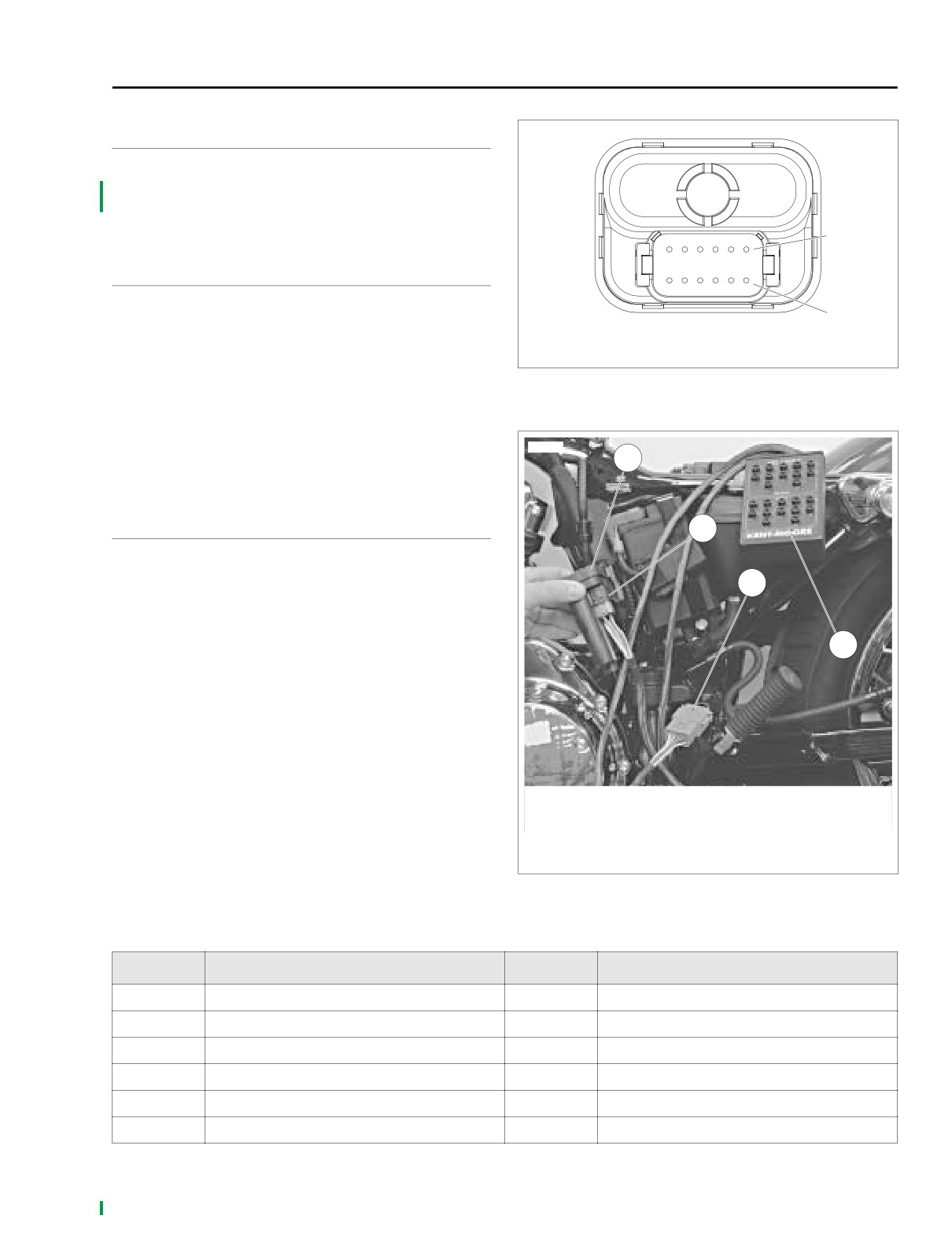
The BREAKOUT BOX (Part No. HD-42682) splices into the
main harness. Used in conjunction with a digital volt/ohmme-
ter (DVOM), it allows circuit diagnosis of wiring harness and
connections without having to probe with sharp objects.
2
INSTALLATION
1. Gain access to TSM/TSSM. See the Sportster Service
Manual.
1
1.
Terminal 1
2. See Figure 3-14. Depress latches on connector [30B].
2.
Terminal 12
3. See Figure 3-15. Attach Breakout Box to connector.
Figure 3-14. TSM/TSSM Connector Terminals
a. Mate gray socket housing on Breakout Box with
TSM/TSSM connector [30A].
b. Mate gray pin housing on Breakout Box with wire
11532
harness connector [30B].
1
4. Reinstall battery and reconnect battery cables.
REMOVAL
2
1. See Figure 3-14. Depress latches on connector [30B].
2. Detach gray Breakout Box connector from TSM/TSSM
3
connector [30A].
3. Detach gray Breakout Box connector from wire harness
connector [30B].
4
4. Disconnect battery cables and remove battery.
5. Reinstall TSM/TSSM. See the Sportster Service Manual.
6. Install parts removed for access.
NOTE
Vehicle will not start with TSM/TSSM disconnected or incor-
rectly mounted.
1.
TSM/TSSM
2.
TSM/TSSM connector [30A]
3.
Wire harness connector [30B]
4.
Breakout Box (Part no. HD-42682)
Figure 3-15. Breakout Box: TSM/TSSM
Table 3-12. TSM/TSSM Connector [30B]
TERMINAL
FUNCTION
TERMINAL
FUNCTION
1
Battery
7
Right turn switch input
2
Ignition
8
Left turn switch input
3
serial data
9
Start relay control
4
Security lamp
10
Ignition enable signal (not used)
5
Left turn feed
11
Alarm signal
6
Right turn feed
12
Ground
2006 Sportster: TSM & TSSM
3-29
HOME
NO SECURITY LAMP AT KEY ON
3.12
GENERAL
x0523x3x
No TSSM Power (Security Equipped
Vehicles Only)
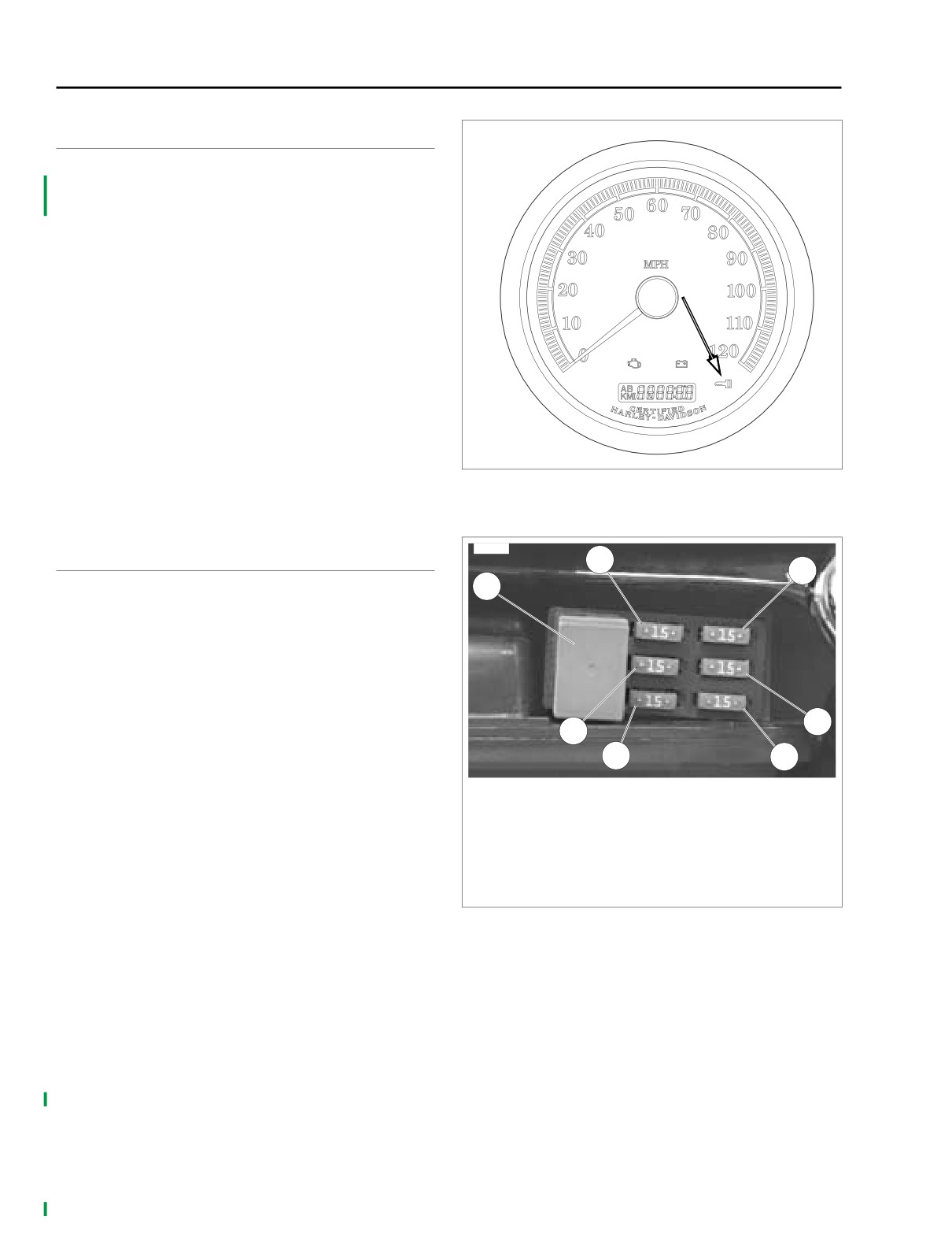
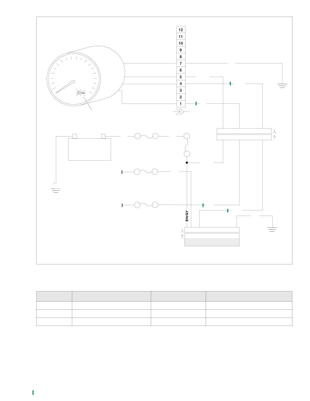
See Figure 3-16. When the Ignition/Light Key Switch is turned
to IGNITION, the security lamp should illuminate for 4 sec-
onds. Following the initial period of illumination, the lamp
should go off for 4 seconds. It may then come back on for an
8 second period, indicating a historic diagnostic trouble code
(DTC) or remain on, indicating a current DTC.
Power and ground are supplied to the Security lamp from the
speedometer circuitry. The TSSM activates an LED driver cir-
cuit in the speedometer to illuminate the security lamp. A lack
of power to the TSSM will cause the security lamp to be inop-
erative and will also create a no start situation.
Job/Time Code Values
Dealership technicians filing warranty claims should use the
Figure 3-16. Security Lamp
job/time code values printed in bold text underneath the
appropriate repair.
10071
DIAGNOSTICS
2
5
1
Diagnostic Tips
● Check for open in BN/V wire.
● Check for blown battery fuse. See Figure 3-17.
Diagnostic Notes
The reference numbers below correlate with the circled num-
6
bers on the Test 3.12 flow charts.
3
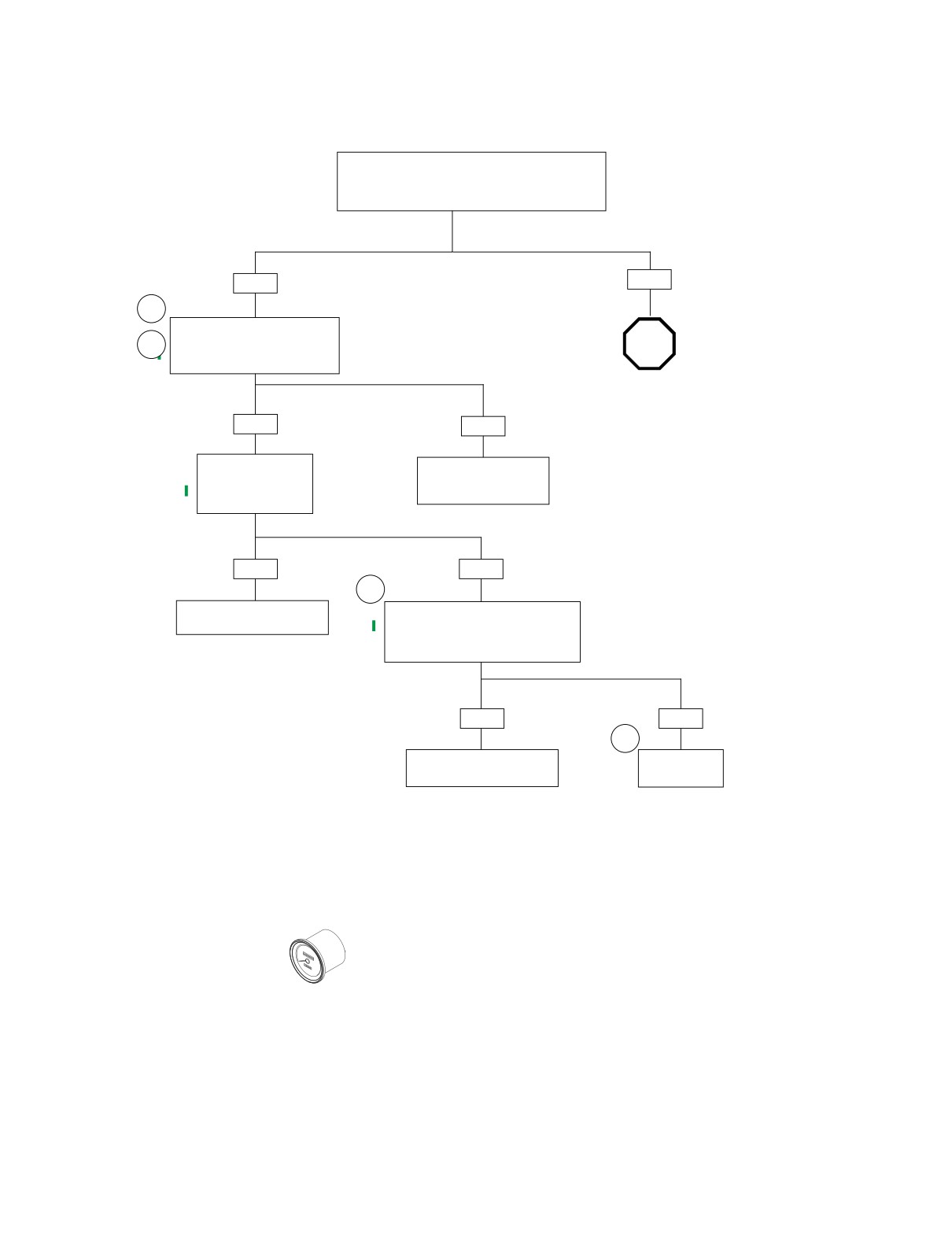
1.
Connect BREAKOUT BOX (Part No. HD-42682) (gray)
4
7
as follows:
1.
Starter relay
a. Mate gray socket housing on Breakout Box with
2.
Accessories fuse
TSM/TSSM connector [30A].
3.
Battery fuse
b. Mate gray pin housing on Breakout Box with wire
4.
Lights fuse
harness connector [30B].
5.
Ignition fuse
2. Connect BREAKOUT BOX (Part No. HD-42682) (black)
6.
Instruments fuse
7.
Spare fuse
as follows:
a. Mate black socket housing on Breakout Box with
Figure 3-17. Relay/Fuse Panel
speedometer connector [39A] (at the back of the
speedometer) using INSTRUMENT HARNESS
ADAPTERS (Part No.HD-46601).
b. Mate black pin housing on Breakout Box with wire
harness connector [39B] using INSTRUMENT HAR-
NESS ADAPTERS (Part No.HD-46601).
3. Use HARNESS CONNECTOR TEST KIT (Part No. HD-
41404), purple pin probe and patch cord between break-
out Breakout Box and ground. Align blade with slot in
cavity of Breakout Box.
4. Security lamp failure requires speedometer replacement.
See the Sportster Service Manual.
3-30
2006 Sportster: TSM & TSSM
HOME
x0539x3x
Ground
BK
Battery
BN/GY
Security LED
BN/V
Ignition
O
Security lamp
(inside speedometer)
[39A]
[39B]
[20B]
1
2
3
4 5 6
7
8
9 10
11
12
R
R
1
2
3
4 5 6
7
8
9 10
11
12
[20A]
15 Amp
-
+
30 Amp
Battery
Main Fuse
Fuse
Battery
BN/GY
+12V
GY
15 Amp
Ignition Fuse
BK
+12V
O
15 Amp
BN/V
BK
Instrument Fuse
[30B]
1
2
3
4 5 67
8
9
10 11 12
[30A]
1
2
3
4 5 67
8
9
10 11 12
TSM/TSSM
Figure 3-18. Security Lamp Circuit
Table 3-13. Wire Harness Connectors in Figure 3-18.
NO.
DESCRIPTION
TYPE
LOCATION
[20]
Instruments
12-Place Deutsch
under fuel tank
[30]
TSM/TSSM
12-place Deutsch
under battery
[39]
Speedometer
12-place Packard
back of speedometer
2006 Sportster: TSM & TSSM
3-31
HOME
Test 3.12 (Part 1 of 3)
NO SECURITY LAMP AT KEY ON
Security equipped vehicles only.
Turn Ignition/Light Key Switch to IGNITION.
Set engine stop switch to RUN. Press starter
button. Turn ignition switch to OFF.
Did engine crank when starter button was pressed?
NO
YES
1
Check for continuity between
Breakout Box cavity 4 (black) and
2
STOP
cavity 4 (gray).
Is continuity present?
Go to Test 3.12
(Part 2 of 3).
YES
NO
Check for continuity to
Repair open on BN/V wire
ground on Breakout
between connectors [30B]
Box cavity 4 (black).
and [39B].
Is continuity present?
6735
YES
NO
3
Locate and repair short to
Reconnect connector [39]. Place
ground on BN/V wire.
jumper between Breakout Box cavity 4
(gray) and battery positive terminal.
6736
Does security lamp illuminate?
YES
NO
4
Replace TSM/TSSM. Learn
Replace
password and perform setup.
speedometer.
6737
6738
Clear DTCs using speedometer self diagnostics. See
3.10 SPEEDOMETER SELF DIAGNOSTICS. Confirm
proper operation with no security lamp.
3-32
2006 Sportster: TSM & TSSM
HOME
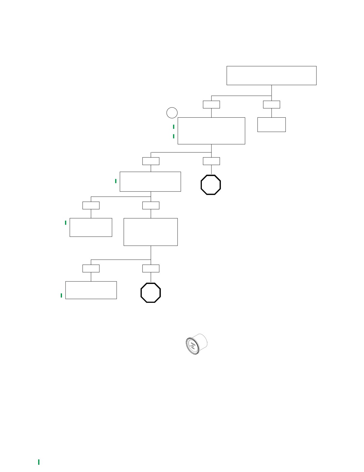
Test 3.12 (Part 2 of 3)
NO SECURITY LAMP AT KEY ON
Continued from Test 3.12 (Part 1 of 3).
Is connector [30] fully mated?
YES
NO
1
Place red meter lead at Breakout
Mate
Box cavity 1 (gray) and black meter
connector.
lead at Breakout Box
6739
cavity 12 (gray).
Is battery voltage present?
YES
NO
Move red meter lead to
Breakout Box cavity 2 (gray).
Is battery voltage present?
STOP
Go to Test 3.12
YES
NO
(Part 3 of 3).
Replace TSSM.
Remove left side cover.
Learn password and
Check for voltage at ignition
perform setup.
fuse. See Figure 3-17.
Is battery voltage present
6740
on both terminals?
YES
NO
Locate and repair open on
gray wire between ignition
STOP
fuse and TSSM.
6741
Go to 4.11 NO
SPARK/NO ICM
POWER.
Clear DTCs using speedometer self diagnostics. See
3.10 SPEEDOMETER SELF DIAGNOSTICS. Confirm
proper operation with no security lamp.
2006 Sportster: TSM & TSSM
3-33
HOME
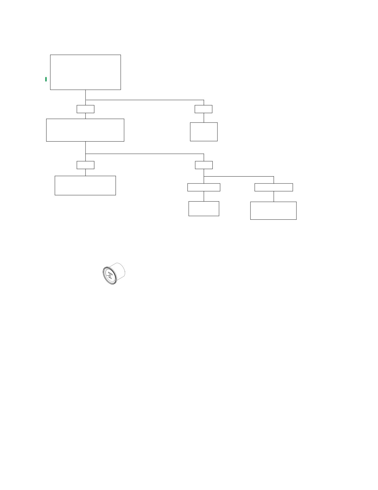
Test 3.12 (Part 3 of 3)
NO SECURITY LAMP AT KEY ON
Continued from
Test 3.12 (Part 2 of 3).
Check resistance to ground at
Breakout Box cavity12 (gray).
Is resistance less than 1 ohm?
YES
NO
Check for 12 volts at both terminals of
15 amp battery fuse. See Figure 3-17.
Locate and
Is proper voltage present at
repair poor
both terminals?
ground.
6742
YES
NO
Locate and repair open in
BN/GY wire between battery
One Terminal.
Neither terminal.
fuse and TSM/TSSM.
6743
Replace
Locate and repair
battery fuse.
open between main
fuse and fuse block.
6744
6745
Clear DTCs using speedometer self diagnostics. See
3.10 SPEEDOMETER SELF DIAGNOSTICS. Confirm
proper operation with no security lamp.
3-34
2006 Sportster: TSM & TSSM
HOME
SECURITY LAMP ON CONTINUOUSLY
3.13
GENERAL
x0523x3x
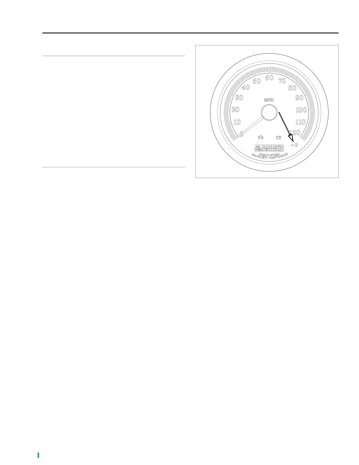
See Figure 3-19. When the Ignition/Light Key Switch is turned
to IGNITION, the security lamp should illuminate for 4 sec-
onds. Following the initial period of illumination, the lamp
should go off for 4 seconds. It may then come back on for an
8 second period, indicating a historic diagnostic trouble code
(DTC) or remain on, indicating a current DTC.
Job/Time Code Values
Dealership technicians filing warranty claims should use the
job/time code values printed in bold text underneath the
appropriate repair.
DIAGNOSTICS
Diagnostic Notes
Figure 3-19. Security Lamp
The reference number below correlates with the circled num-
ber on the Test 3.13 flow chart.
1. Connector [39B] is on the back of the speedometer. Use
HARNESS CONNECTOR TEST KIT (Part No. HD-
41404), black pin probe and patch cord.
2006 Sportster: TSM & TSSM
3-35
HOME
x0539x3x
Ground
BK
Battery
BN/GY
Security LED
Ignition
Security lamp
(inside speedometer)
[39A]
[39B]
[20B]
1
2
3
4 5 6 7 8 9 10 11 12
R
R
1
2
3
4 5 6 7 8 9 10 11 12
[20A]
15 Amp
-
+
30 Amp
Battery
Main Fuse
Fuse
Battery
BN/GY
+12V
GY
15 Amp
Ignition Fuse
BK
+12V
BN/V
15 Amp
BK
Instrument Fuse
[30B]
1
2
3
4 5 6 7 8 9 10 11 12
[30A]
1
2
3
4 5 6 7 8 9 10 11 12
TSM/TSSM
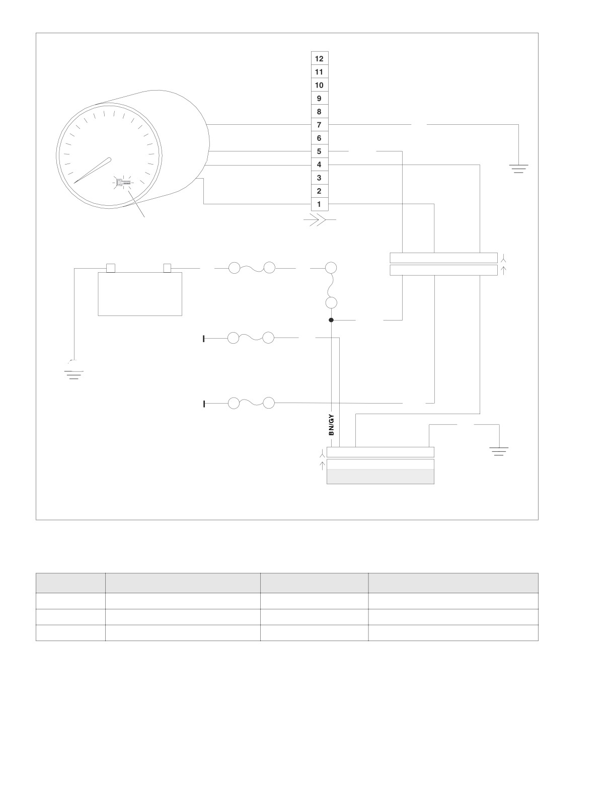
Figure 3-20. Security Lamp Circuit
Table 3-14. Wire Harness Connectors in Figure 3-20.
NO.
DESCRIPTION
TYPE
LOCATION
[20]
Instruments
12-Place Deutsch
under fuel tank
[30]
TSM/TSSM
12-place Deutsch
under battery
[39]
Speedometer
12-place Packard
back of speedometer
3-36
2006 Sportster: TSM & TSSM
HOME
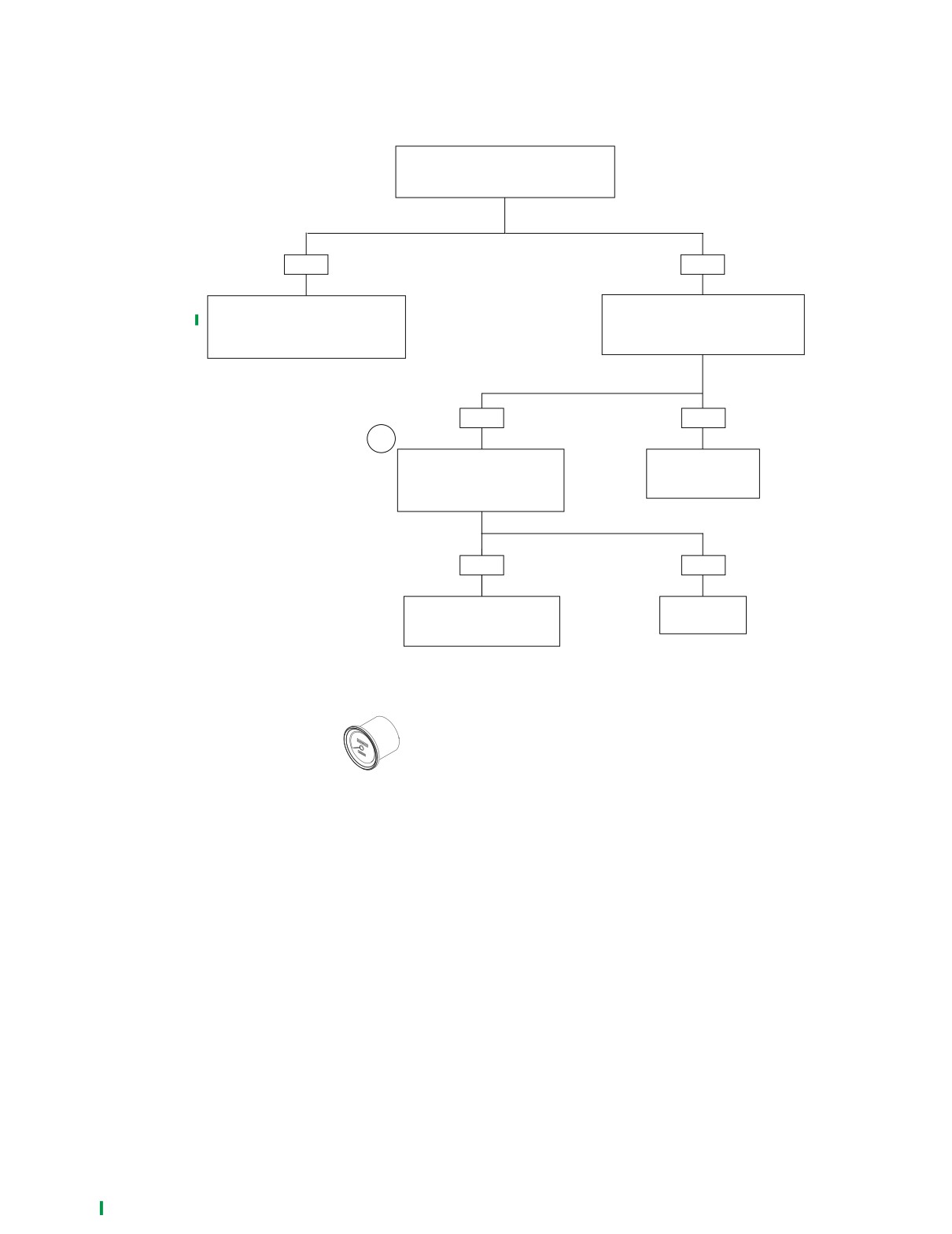
Test 3.13
SECURITY LAMP ON CONTINUOUSLY
Turn Ignition/Light Key Switch to IGNITION.
Does security lamp turn ON for 4 seconds
and then turn OFF for 4 seconds?
YES
NO
Security lamp function OK. Check for
Turn Ignition/Light Key Switch to OFF.
diagnostic trouble codes. See Section
Disconnect TSM/TSSM connector [30].
3.8 CHECKING FOR DIAGNOSTIC
Turn switch to IGNITION.
TROUBLE CODES.
Does security lamp illuminate?
YES
NO
1
Disconnect connector [39].
Replace TSM/TSSM.
Check for voltage on terminal 4
Learn password and
(BN/V wire) of connector [30].
perform setup.
Is voltage present?
6750
YES
NO
Repair short to battery
Replace
on BN/V wire between
speedometer.
connectors [30A] and [39B].
6752
6751
Clear DTCs using speedometer self diagnostics. See
3.10 SPEEDOMETER SELF DIAGNOSTICS. Confirm
proper operation with no security lamp.
2006 Sportster: TSM & TSSM
3-37
HOME
NOTES
3-38
2006 Sportster: TSM & TSSM
HOME
KEY FOB SIGNAL TO TSSM WEAK OR FAILS
3.14
GENERAL
o0235xox
Security Equipped Vehicles Only
This section applies only to those vehicles equipped with the
optional security system.
NOTE
Disarming function may require practice. The key fob button
must be pressed twice within 1.5 seconds to send the disarm
command. The action is very similar to double-clicking a com-
puter mouse. Light quick taps work best; very hard or very
slow taps are less likely to work.
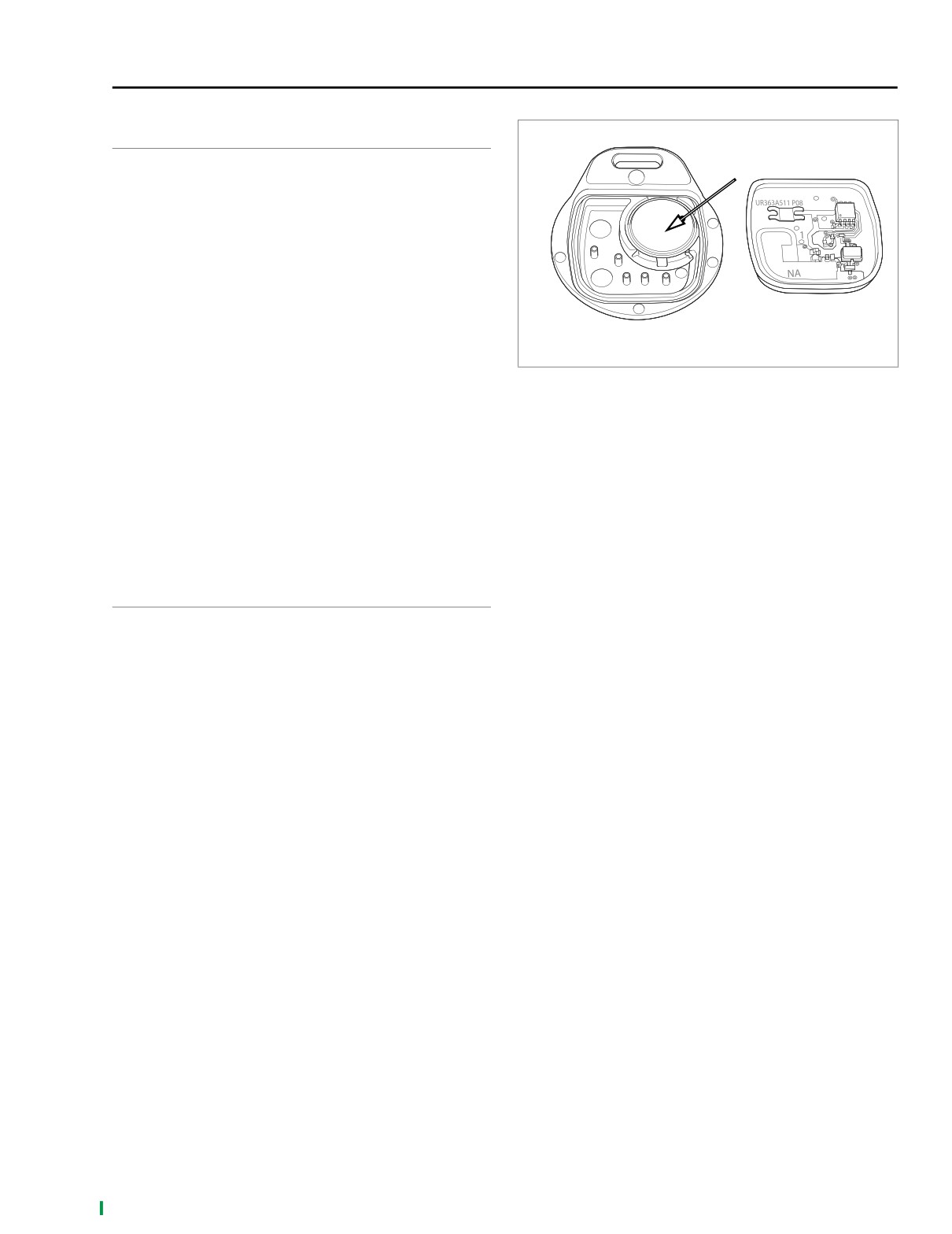
See Figure 3-21. The key fob sends a RF signal to activate all
remote TSSM functions. The left front turn signal switch wire
Figure 3-21. Key Fob Battery
serves as the vehicle’s antenna. If the TSSM does not
respond (no confirmation at arming/disarming system) or
Diagnostic Notes
responds weakly (limited range, won’t consistently arm/dis-
The reference number below correlates with the circled num-
arm or synchronize), follow the Test 3.14 flow chart.
ber on the Test 3.14 flow chart.
Job/Time Code Values
1. After a battery disconnect, the TSSM will not enter the
configuration mode on the first attempt. All attempts to
Dealership technicians filing warranty claims should use the
assign a fob or enter the configuration mode will require
job/time code values printed in bold text underneath the
at least two attempts.
appropriate repair.
DIAGNOSTICS
Diagnostic Tips
● Verify key fob battery voltage is at least 2.9 volts. See
3.24 TSSM MAINTENANCE.
● Interference from physical surroundings may affect RF
transmission. Place fob next to left handgrip and disarm
with two clicks or move motorcycle to a new location and
retest.
● Check for damage to antenna wire. Does left turn signal
work?
NOTE
See
3.7 ARMING/DISARMING SECURITY SYSTEM
(TSSM). Use only the proper key fob for your market and
TSSM package.
2006 Sportster: TSM & TSSM
3-39
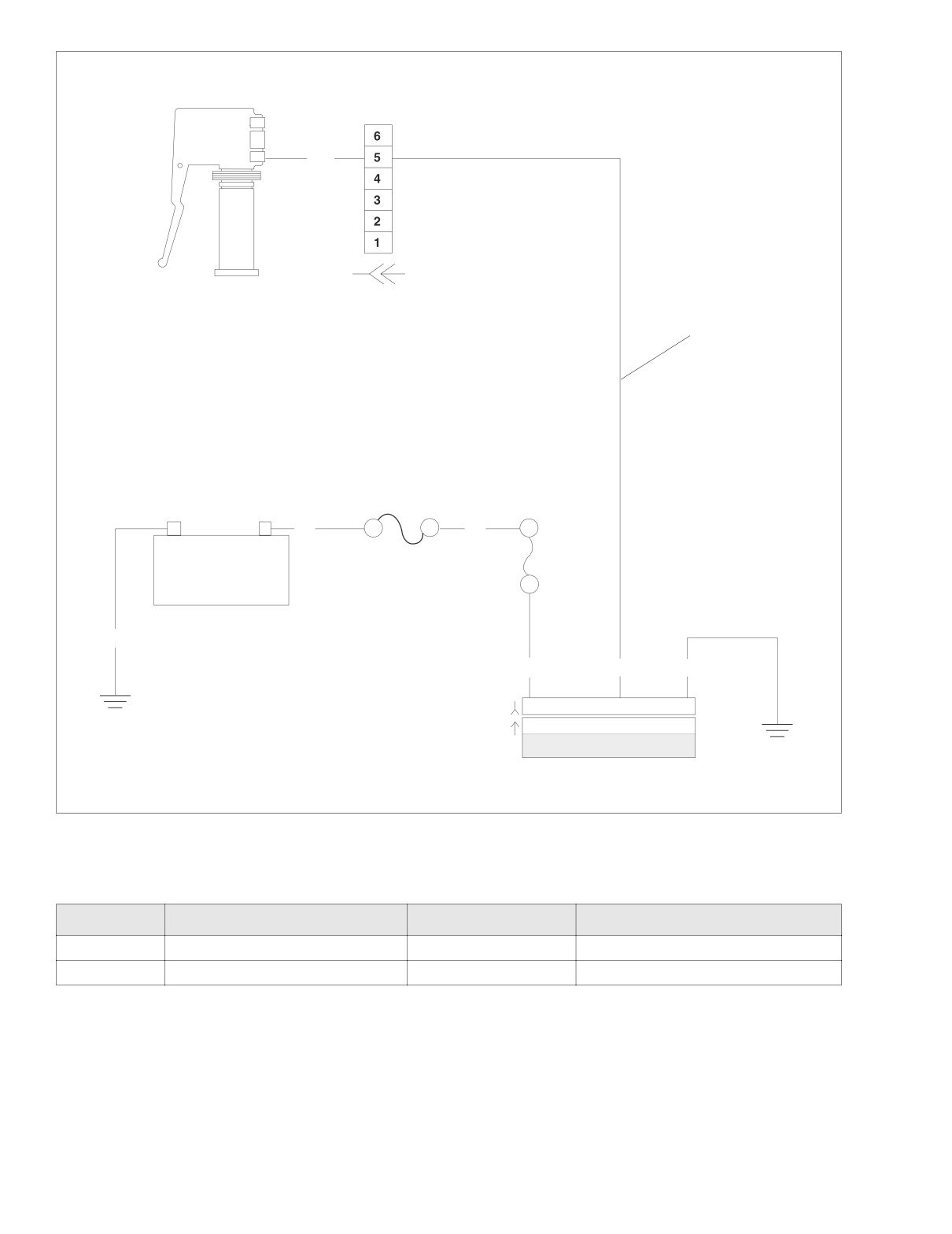
HOME
x0534a3x
W/V
Left turn signal
[24B]
[24A]
switch
Key Fob
Antenna
30 Amp
main fuse
R
R
–
+
15 Amp
security
fuse
Battery
BK
BN/GY
W/V
BK
[30B]
1
2
3
4 5 6 7 8 9 10 11 12
1
2
3
4 5 6 7 8 9 10 11 12
[30A]
TSSM
Figure 3-22. Antenna Circuit
Table 3-15. Wire Harness Connectors in Figure 3-22.
NO.
DESCRIPTION
TYPE
LOCATION
[24]
Left handlebar switch
6-place Deutsch
under fuel tank
[30]
TSSM
12-place Deutsch
under battery
3-40
2006 Sportster: TSM & TSSM
HOME
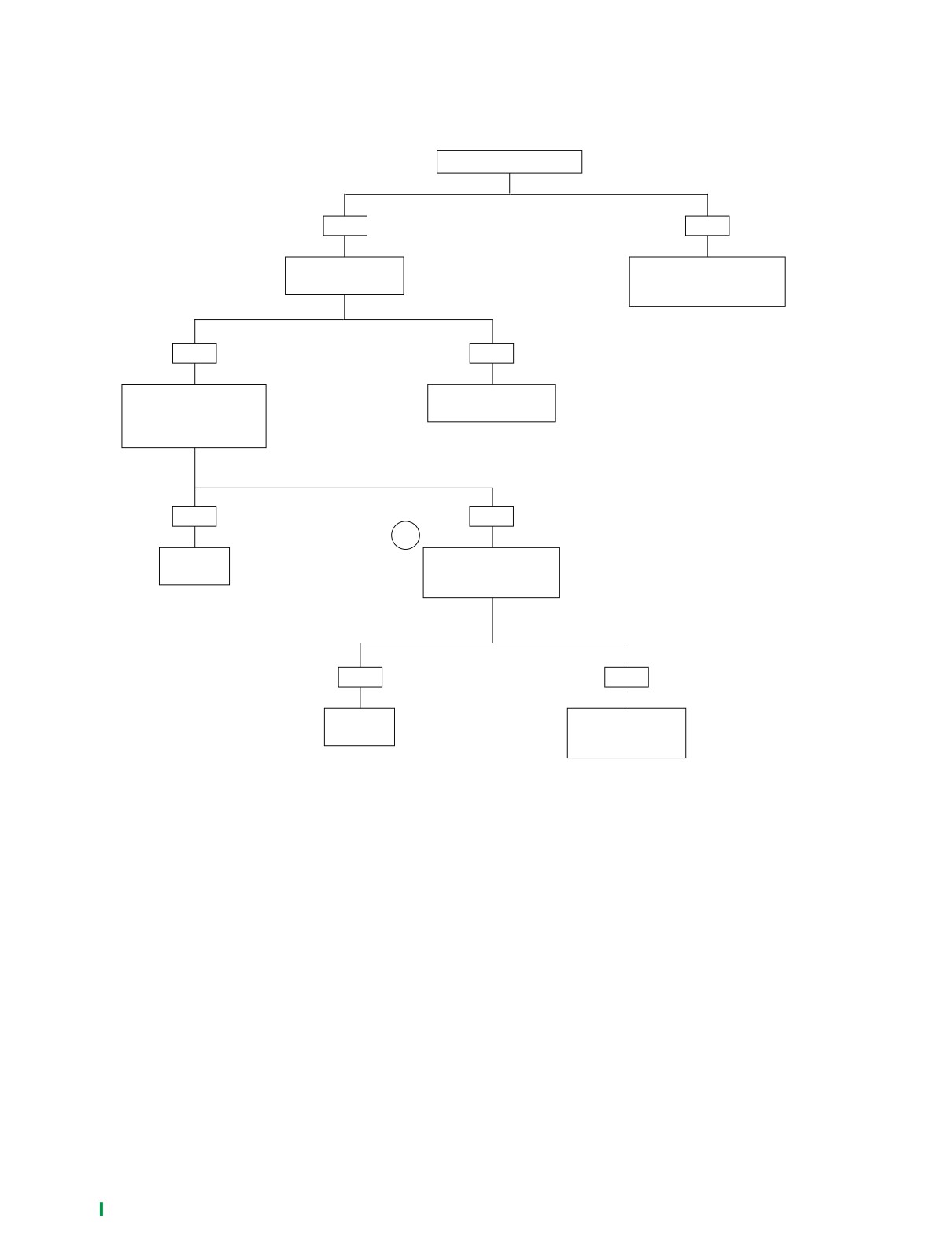
Test 3.14
KEY FOB SIGNAL TO TSSM WEAK OR FAILS
Correct key fob for vehicle?
YES
NO
Does left turn
Obtain correct fob or replace
signal function?
fob. Verify fob is synchronized
to vehicle’s TSSM.
YES
NO
Replace fob battery and
See 3.15 TURN SIGNAL
retest. See 3.24 TSSM
ERRORS: DTC B1121,
MAINTENANCE.
Does fob work?
YES
NO
1
System
Attempt to assign new fob
OK.
to TSSM and retest.
Does fob work?
6755
YES
NO
System
Replace TSSM.
OK.
Perform password
learn and setup.
6756
6757
2006 Sportster: TSM & TSSM
3-41
HOME
TURN SIGNAL ERRORS: DTC B1121, B1122, B1141
3.15
GENERAL
7844
The turn signals will automatically cancel either based on the
speed/acceleration of the vehicle or based upon turn comple-
tion. See 3.4 TSM/TSSM TURN SIGNAL FUNCTIONS.
For turn signal diagnostics, refer to Table 3-16.
Job/Time Code Values
Dealership technicians filing warranty claims should use the
job/time code values printed in bold text underneath the
appropriate repair.
DIAGNOSTICS
Diagnostic Tips
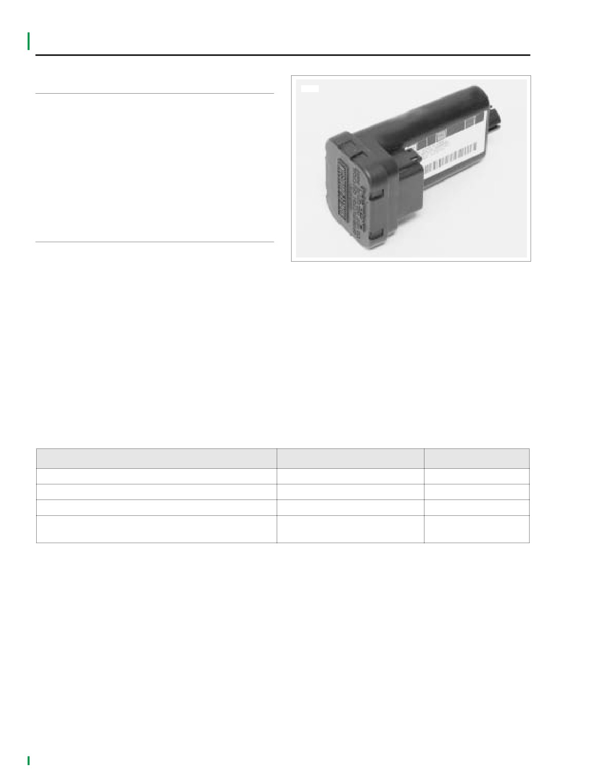
Figure 3-23. TSM/TSSM
● Diagnostic trouble code (DTC) B1121 and B1122 will illu-
minate the security lamp.
● DTC B1141 will not illuminate the security lamp.
● When the TSM/TSSM is in four-way flasher mode, a fault
on either the left or right turn lamp output will not cause
either DTC B1121 and DTC B1122 to be set. If fault
occurs on both left and right outputs, then both DTC
B1121 and DTC B1122 will be set.
● When the TSM/TSSM detects an over current (or short to
ground) condition, it will turn off the turn lamp outputs.
The outputs will be automatically reactivated once the
fault is removed.
Table 3-16. Turn Signal Errors
SYMPTOM
START WITH FLOW CHART
DTC(S)
Turn signals will not cancel upon turn completion
Turn Signal Error 1A (Part 1 of 2)
N/A
Turn signals cancel erratically
Turn Signal Error 1A (Part 2 of 2)
N/A
Turn signals will not flash, 4-way flashers inoperable
Turn Signal Error 2A
B1121, B1122, B1141
Left or right turn signals flash at double the normal rate
Turn Signal Error 3A
N/A
while all bulbs are working
3-42
2006 Sportster: TSM & TSSM