Harley Davidson 2006 Sportster XLH MODELS. Service Manual - page 19
HOME
REMOVAL
11351
1.
Remove seat. See REMOVAL under 2.32 SEAT.
2.
Remove left side cover. No tools are required. See 1.6
LEFT SIDE COVER.
1
1WARNING
Prevent accidental vehicle start-up, which could cause
death or serious injury. First disconnect negative (-) bat-
tery cable at engine and then positive (+) cable from bat-
tery. (00280a)
2
3.
Disconnect battery cables, negative cable first. See
BATTERY DISCONNECTION AND REMOVAL under 1.7
BATTERY MAINTENANCE.
4.
Drain oil tank as follows
(the oil filter need not be
3
removed unless it is due to be replaced):
a. Remove filler cap/dipstick assembly from oil tank.
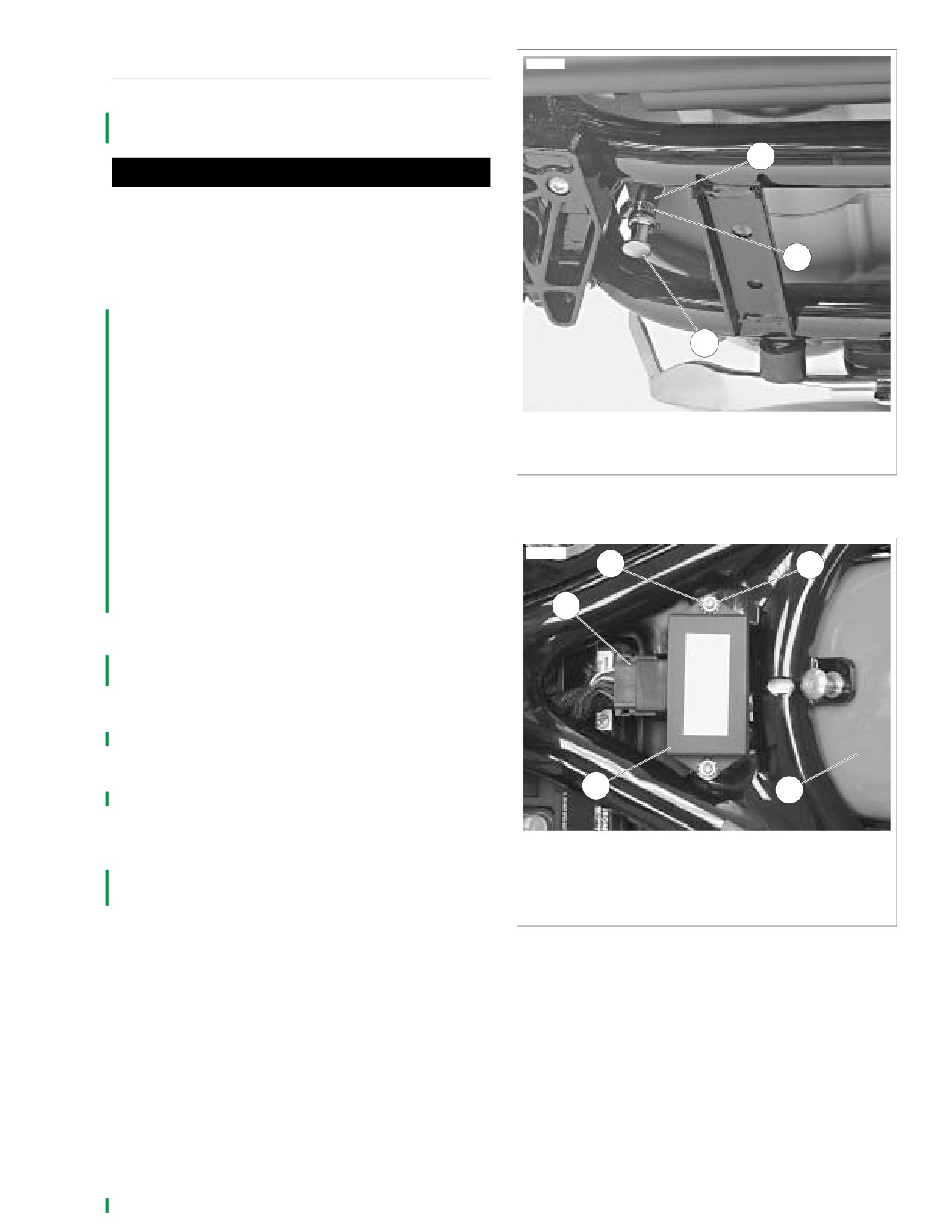
b. See Figure 3-128. Place a suitable container directly
under the drain hose (1) at the bottom rear of the
1.
Oil tank drain hose
engine crankcase. The container must be able to
2.
Worm drive clamp
hold approximately four quarts (U.S.) (3.8 liters).
3.
Drain plug
c. Loosen worm drive clamp (2) and pull drain plug (3)
from end of drain hose. Completely drain engine oil
Figure 3-128. Oil Tank Drain Hose
from oil tank.
d. Replace drain plug into end of drain hose and
tighten worm drive clamp securely.
10057
5.
Remove right side cover by gently prying bottom lip off
5
2
tab on oil tank.
6.
See Figure 3-129. Disconnect ICM connector [10] (1).
1
Remove two locknuts (2) and remove ICM (3) from
mounting studs (5).
7.
Remove rear belt guard. See 2.30 BELT GUARD AND
DEBRIS DEFLECTOR.
NOTE
For ease of assembly, mark oil tank hoses for identification;
oil feed, drain, vent and return, as they are removed from oil
tank.
8.
See Figure 3-130. Remove clamp (22) and disconnect
3
4
drain hose (9) from oil tank (1).
9.
Remove clamp (20) and disconnect feed oil hose (8)
from oil tank.
1.
ICM connector [10]
10. Remove clamp (16) and disconnect return oil hose (6)
2.
Locknut (2)
from oil tank.
3.
ICM
11. Remove rear fender. See 2.29 REAR FENDER.
4.
Rear fender
5.
Mounting stud (2)
12. See Figure 3-130. Remove clamp (18) and disconnect
vent oil hose (7) from oil tank (1).
Figure 3-129. Ignition Control Module (ICM) Removal
13. Remove two mounting studs (5) and screw (4).
14. Remove oil tank from right side of motorcycle. As oil tank
is being removed, unlatch fuse block (23).
2006 Sportster: Engine
3-103
HOME
x0465c3x
5
23
3
4
2
16
6
1
18
7
22
17
20
12
13
9
19
8
14
24
21
15
11
10
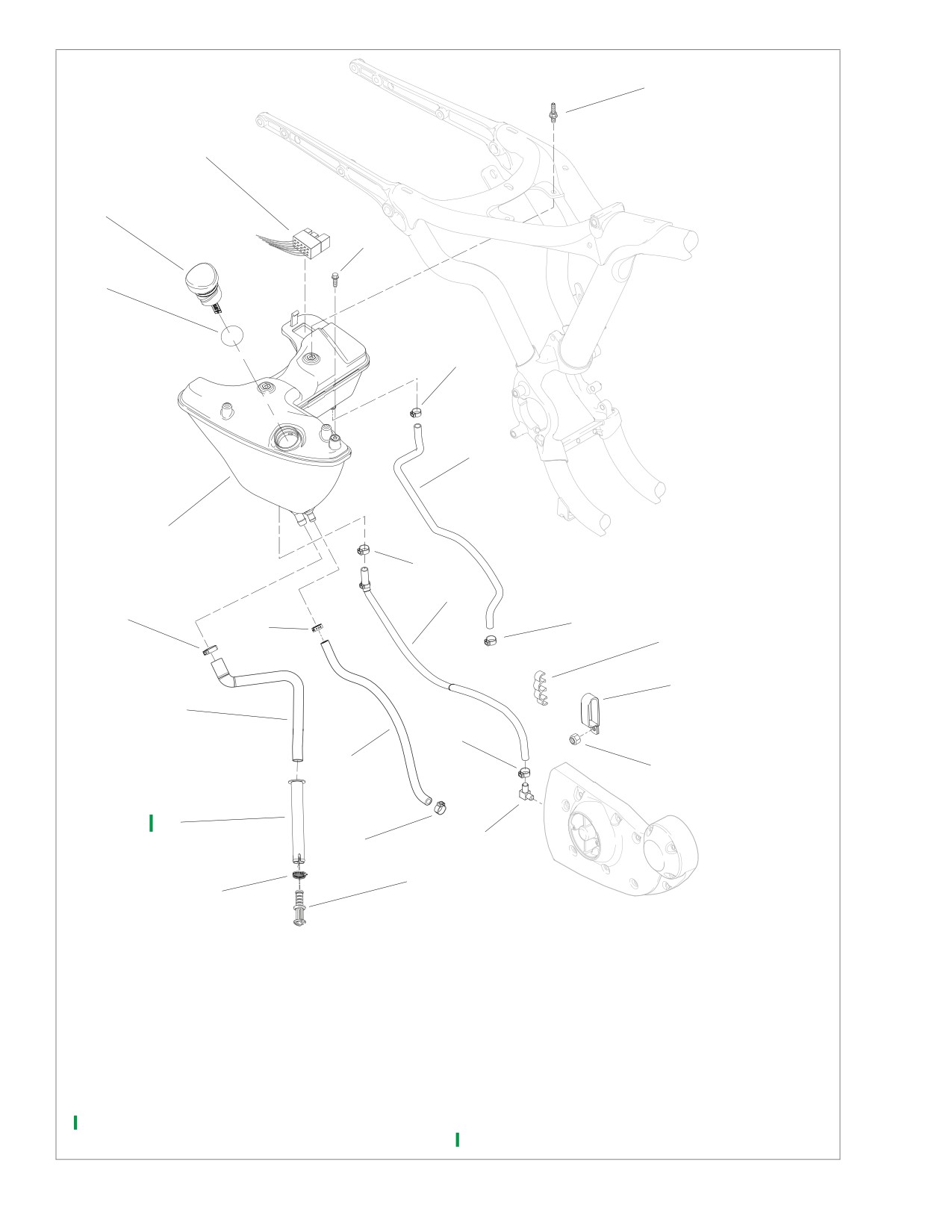
1.
Oil tank
13.
Clamp
2.
O-ring
14.
Locknut
3.
Filler cap/dipstick
15.
Elbow fitting
4.
Screw
16.
Clamp
5.
Mounting stud (2)
17.
Clamp
6.
Return oil hose
18.
Clamp
7.
Vent oil hose
19.
Clamp
8.
Feed oil hose
20.
Clamp
9.
Drain oil hose
21.
Clamp
10.
Worm drive clamp
22.
Clamp
11.
Drain plug
23.
Fuse block
12.
Hose clip
24.
Oil drain hose sleeve
Figure 3-130. Engine Oil Tank Assembly
3-104
2006 Sportster: Engine
HOME
7. Install right side cover. No tools are required for this
INSTALLATION
operation.
1.
See Figure 3-130. Slide oil tank (1) into frame from right
8. See Figure 3-130. Fill oil tank (1) and install filler cap/dip-
side of vehicle. As you slide oil tank into place, latch fuse
stick (3). See CHECKING AND ADDING OIL under 1.5
block (23) into slot in upper left rear corner of oil tank.
ENGINE OIL AND FILTER.
2.
Install screw (4) and two mounting studs (5) to secure oil
9. Install battery cables, positive (+) cable first. See BAT-
tank to frame. Tighten all three fasteners to 36-60 in-lbs
TERY INSTALLATION AND CONNECTION under 1.7
(4.1-6.8 Nm).
BATTERY MAINTENANCE.
3.
Install marked oil vent hose (7), feed hose (8), drain hose
10. Install left side cover. No tools are required for this opera-
(9) and return hose (6) in their proper locations on oil
tion.
tank fittings. Secure with new clamps (20, 22, 18, 16).
4.
Install rear fender. See 2.29 REAR FENDER.
1WARNING
5.
Install rear belt guard. See
2.30 BELT GUARD AND
After installing seat, pull upward on front of seat to be
DEBRIS DEFLECTOR.
sure it is in locked position. While riding, a loose seat can
6.
See Figure 3-129. Install ICM (3). Tighten lock nuts (2) to
shift causing loss of control, which could result in death
12-20 in-lbs (1.4-2.3 Nm). Plug ICM connector [10] (1)
or serious injury. (00070a)
into ICM.
11. Install seat. See INSTALLATION under 2.32 SEAT.
2006 Sportster: Engine
3-105
HOME
NOTES
3-106
2006 Sportster: Engine

HOME
SPECIFICATIONS
4.1
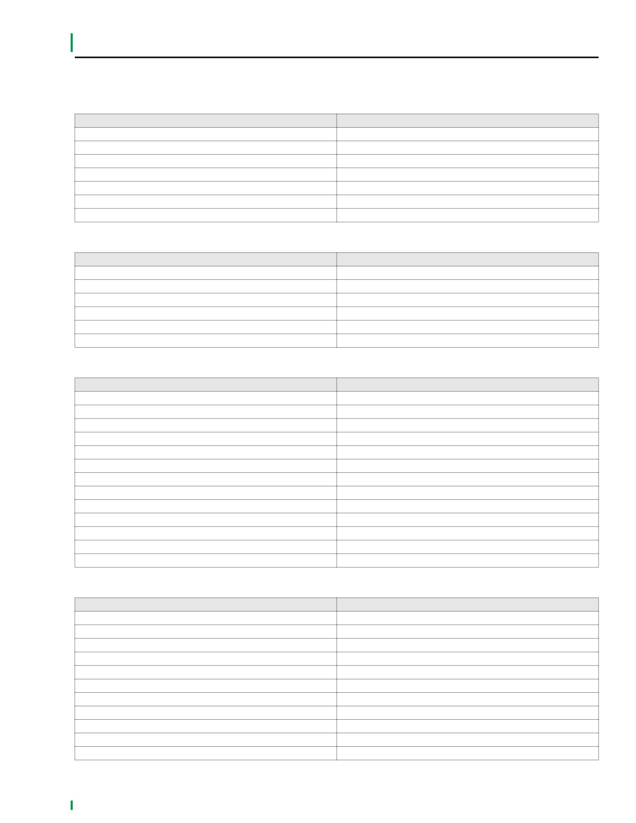
Table 4-1. Carburetor Jet Sizes
XL 883
XL 1200
Jet
49 State
Calif.
HDI, Swiss
49 State
Calif.
HDI, Swiss
Main jet
175
180
170
180
185
160
Slow jet
42
42
42
42
42
42
Table 4-2. Carburetor Adjustments
ENGINE SPEED
RPM
Slow idle
950-1050
Table 4-3. Fuel Tank Capacity
XL 883/XL 883L/XL 883R/XL 1200R
XL 883C/XL 1200C
Gallons (U.S.)
Liters
Gallons (U.S.)
Liters
Total
3.30
12.5
4.5
17.0
Reserve
0.80
3.0
1.0
3.7
2006 Sportster: Fuel System
4-1

HOME
TORQUE VALUES
4.2
ITEM
TORQUE
NOTES
Air cleaner breather screw
84-120 in-lbs
9.5-13.6 Nm
page 4-14
Air cleaner cover screw
36-60 in-lbs
4.1-6.8 Nm
page 4-14
Air filter/backplate screw
40-60 in-lbs
4.5-6.8 Nm
page 4-14
EVAP canister clip mounting
36-60 in-lbs
4.1-6.8 Nm
page 4-26
screw
EVAP canister guard screw
35-45 in-lbs
4.0-5.1 Nm
page 4-26
EVAP canister mounting
17-22 ft-lbs
23.1-29.9 Nm
page 4-26
bracket screw
Fuel tank mounting screw
15-20 ft-lbs
20.4-27.1 Nm
page 4-20
Intake manifold screws
96-144 in-lbs
10.9-16.3 Nm
Page 4-12
4-2
2006 Sportster: Fuel System
HOME
TROUBLESHOOTING
4.3
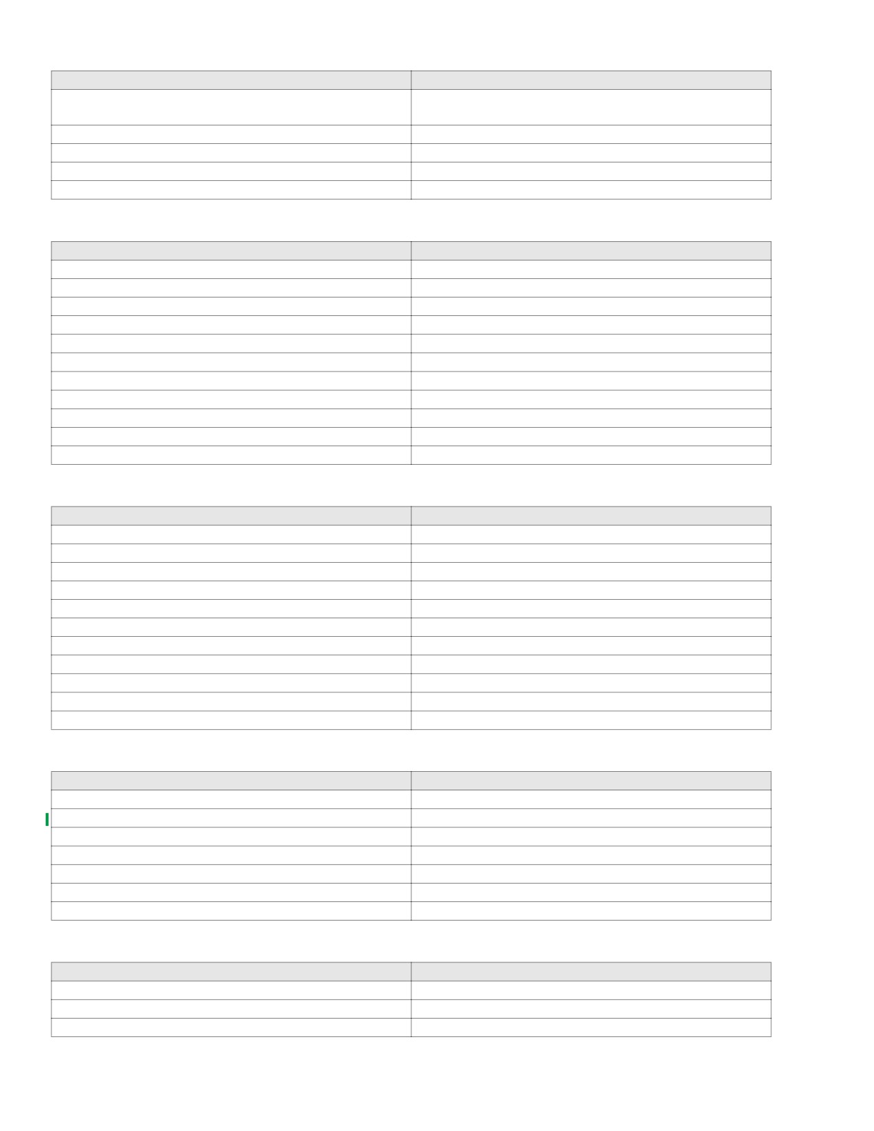
Table 4-4. Overflow
Check for
Remedy
Restricted fuel tank vent system.
Correct restricted hose. Replace vapor valve.
Loose float bowl screws.
Tighten screws.
Damaged float bowl O-ring.
Replace O-ring.
Damaged or leaking float assembly.
Replace float assembly.
Particle contamination in fuel inlet fitting cavity.
Clean and clear cavity and fuel supply tract.
Worn or dirty inlet valve or seat.
Clean or replace valve and clean seat.
Improper fuel level in float bowl.
Adjust float tab for correct fuel level.
Table 4-5. Poor Idling
Check for
Remedy
Idle speed improperly adjusted.
Adjust operating idle speed.
Inlet system air leak (faster idling).
Correct as required.
Loose low speed jet.
Tighten jet.
Contaminated or plugged low speed system.
Clean contaminants and clear passages.
Enrichener valve not seated or leaking.
Adjust, clean or replace.
Leaking accelerator pump.
Repair.
Table 4-6. Poor Fuel Economy
Check for
Remedy
Excessive use of enrichener system.
Limit system use.
Enrichener valve not seated or leaking.
Adjust, clean or replace.
Dirty air cleaner element.
Clean or replace as required.
Restricted fuel tank vent system.
Correct restricted hose. Replace vapor valve.
High speed riding style.
Modify riding habits.
Idle speed improperly adjusted.
Adjust operating idle speed.
Loose jets.
Tighten jets.
Fuel level too high.
Adjust float level.
Plugged or restricted bowl vent.
Clean and clear passages.
Worn or damaged needle or needle jet.
Replace needle or needle jet.
Vacuum piston assembly malfunction.
See Vacuum Piston Troubleshooting at end of this table.
Plugged air jets or passages.
Clean and clear passages.
Excessive accelerator pump output.
Check and clean accelerator pump bypass orifice.
Table 4-7. Poor Acceleration
Check for
Remedy
Throttle cables misaligned.
Adjust throttle cables.
Inlet system air leak.
Correct as required.
Restricted fuel tank vent system.
Correct restricted hose. Replace vapor valve.
Restricted fuel supply passages.
Correct and clear restriction.
Plugged bowl vent or overflow.
Clean and clear passages.
Enrichener valve not seated or leaking.
Adjust, clean or replace.
Worn or damaged needle or needle jet.
Replace assembly.
Vacuum piston malfunction.
See Vacuum Piston Troubleshooting at end of this table.
Plugged jets or passages.
Clean and clear as required.
Fuel level (float chamber) too low.
Adjust float level.
Accelerator pump leaking or no output.
Repair as necessary.
2006 Sportster: Fuel System
4-3
HOME
Table 4-8. Hard Starting
Check for
Remedy
Enrichener system plugged, not properly functioning or
Clean, adjust, or replace; or read Owner's Manual.
improperly operated.
Inlet system air leak.
Correct as required.
Restricted fuel supply
Correct fuel supply or passages.
Fuel overflow.
See Overflow Troubleshooting at beginning of this table.
Plugged slow jet or passages.
Clean and clear jet or passages.
Table 4-9. Poor Performance on Road
Check for
Remedy
Idle speed improperly adjusted.
Adjust operating idle speed.
Inlet system air leak
Correct as required.
Restricted fuel tank vent system
Correct restricted hose. Replace vapor valve.
Dirty or damaged air cleaner element.
Clean or replace.
Enrichener valve not seated or leaking.
Adjust, clean or replace.
Restricted fuel supply tract.
Correct and clear restriction.
Plugged bowl vent or overflow.
Clean and clear passages.
Loose or plugged fuel and air jets or passages.
Clean, clear and correct as required.
Worn or damaged needle or needle jet.
Replace assembly.
Vacuum piston assembly malfunction.
See Vacuum Piston Troubleshooting below.
Accelerator pump inoperative.
Repair as required.
Table 4-10. Poor High-Speed Performance
Check for
Remedy
Inlet system air leak.
Clean or replace.
Enrichener valve not seated or leaking.
Adjust, clean or replace.
Restricted fuel tank vent system.
Correct restricted hose. Replace vapor valve.
Restricted fuel supply tract.
Correct and clean restriction.
Dirty or damaged air cleaner element.
Clean or replace.
Plugged bowl, vent or overflow.
Clean and clear passages.
Worn or damaged needle or needle jet.
Replace assembly.
Vacuum piston assembly malfunction.
See Vacuum Piston Troubleshooting below.
Loose or plugged main jets or passages.
Tighten, clean, clear as required.
Improper fuel level.
Adjust float level.
Accelerator pump inoperative.
Repair as required.
Table 4-11. Piston Does Not Rise Properly
Check for
Remedy
Piston atmosphere vent blocked
Clear vent.
Diaphragm cap loose, damaged or leaking.
Tighten or replace cap.
Spring binding.
Correct or replace spring.
Diaphragm pinched at lip groove
Reposition diaphragm lip.
Torn diaphragm.
Replace piston diaphragm assembly.
Piston binding.
Clean piston slides and body or replace piston.
Piston vacuum passage plugged.
Clean and clear passage.
Table 4-12. Piston Does Not Close Properly
Check for
Remedy
Spring damaged.
Replace spring.
Piston binding.
Clean piston slides and body or replace piston.
Piston diaphragm ring dirty or damaged.
Clean or replace piston.
4-4
2006 Sportster: Fuel System
HOME
ENRICHENER
4.4
GENERAL
d0611x4x
1
2
CAUTION
3
Pay close attention to the vehicle's warm-up time. Either
excessive or insufficient use of the enrichener may
cause poor performance, erratic idle, poor fuel economy,
spark plug fouling and equipment damage. (00164a)
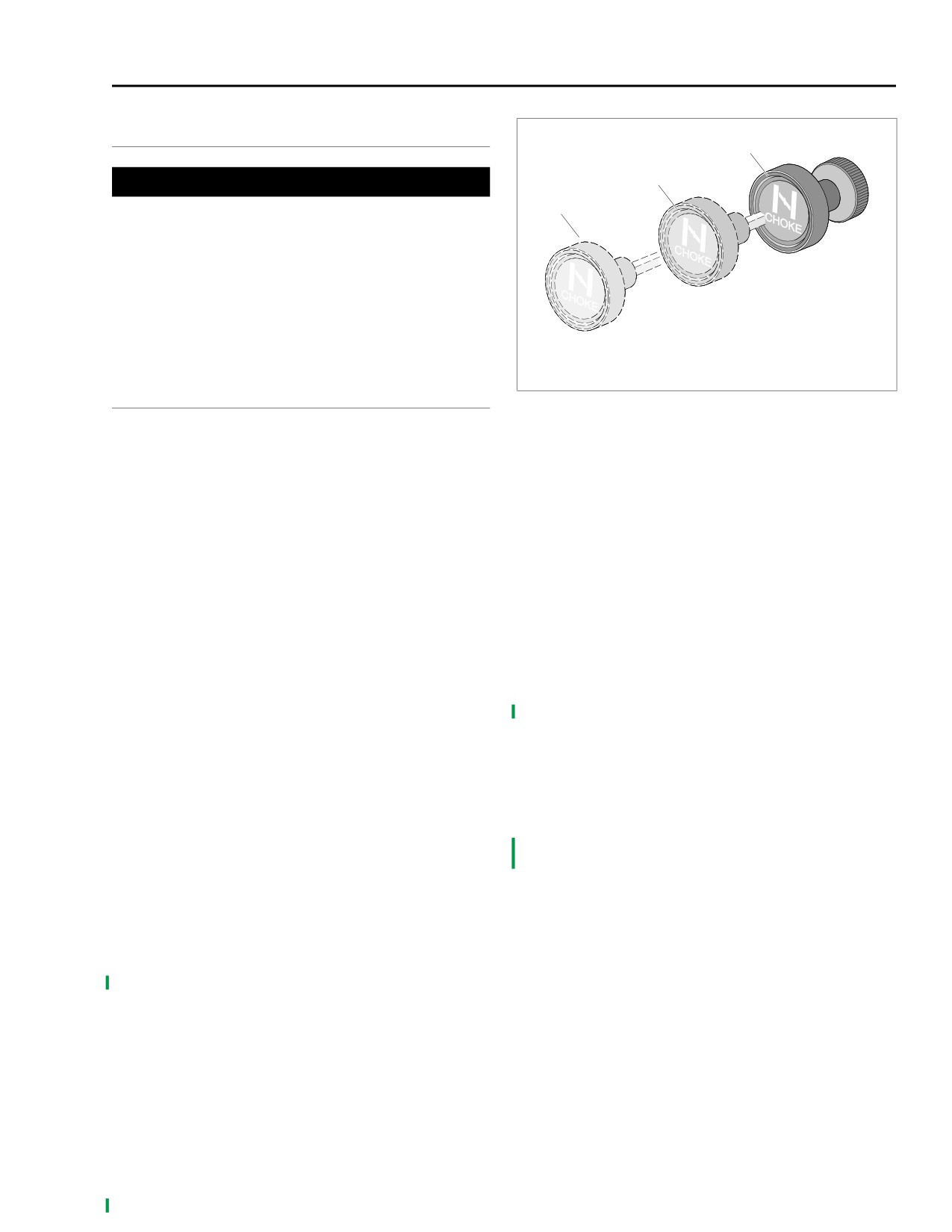
The enrichener knob, labeled CHOKE, and located under the
left side of the fuel tank, controls the opening and closing of
the enrichener circuit in the carburetor. The enrichener knob
can be adjusted to any position, from full-in to full-out.
1.
Normal running position
2.
1/2 way out position
3.
Full-out position
OPERATION
Figure 4-1. Enrichener Operation
NOTES
Outside Temperature Greater Than 60˚ F (16˚ C)
● The following starting and operating instructions for all
BE SURE THROTTLE IS CLOSED. See Figure 4-1. Pull
Harley-Davidson motorcycles are recommendations.
enrichener knob fully out (3). Turn the ignition switch on and
They may be modified for individual vehicles.
press starter switch to operate the electric starter.
● The vehicle should be allowed to warm up for only 15-30
1. After initial 15-30 second warm-up, ride for 1 minute or
seconds before being driven. Initial warm-up periods
0.5 mile (0.8 km) with the enrichener knob in full-out
longer than 30 seconds are not recommended.
position (3).
Cool Engine
2. After 1 minute or 0.5 mile (0.8 km), push the enrichener
knob in to the 1/2 way position (2). Ride 1 minute or
Outside Temperature Less Than 60˚ F (16˚ C)
0.5 mile (0.8 km).
BE SURE THROTTLE IS CLOSED. See Figure 4-1. Pull
3. After 1 minute or 0.5 mile (0.8 km), push the enrichener
enrichener knob fully-out (3). Turn the ignition switch on and
knob fully in to the normal running position (1).
press starter switch to operate the electric starter.
NOTE
NOTE
If engine will not idle at specified RPM, pull out enrichener
For temperatures below 20° F (-6.7° C), you may need to
knob enough to allow correct idle speed. Ride another two
pump the throttle once or twice immediately before attempt-
minutes or 2 miles (3 km); then push enrichener knob fully in.
ing engine start-up. This will add extra fuel from the carbure-
tor accelerator pump to assist the start-up.
Warm or Hot Engine
1.
After initial 15-30 second warm-up, ride for 3 minutes or
Open throttle 1/8-1/4 of full travel. Turn on ignition switch and
2 miles (3.2 km) with the enrichener knob in full-out posi-
operate electric starter. DO NOT USE ENRICHENER unless
tion (3).
engine will not idle at specified RPM. If engine will not idle at
2.
After 3 minutes or 2 miles (3.2 km), push the enrichener
specified RPM, pull out enrichener knob enough to allow cor-
knob in to the 1/2 way position (2). Ride 2 minutes or 2
rect idle speed. Ride 2 minutes or 2 miles (3 km); then push
miles (3.2 km).
enrichener knob fully in.
3.
After 2 minutes or 2 miles (3.2 km), push the enrichener
NOTE
knob fully in to the normal running position (1).
If the engine does not start after a few turns or if one cylinder
NOTE
fires weakly but engine does not start, it is usually because of
If engine will not idle at specified RPM, pull out enrichener
an over-rich (flooded) condition. This is especially true of a
knob enough to allow correct idle speed. Ride another two
hot engine. If the engine is flooded, push enrichener knob in
minutes or 2 miles (3 km); then push enrichener knob fully in.
all the way, turn ignition on and operate starter with throttle
wide open. DO NOT “pump” the throttle while turning the
engine over.
2006 Sportster: Fuel System
4-5
HOME
CARBURETOR
4.5
GENERAL
x0506a1x
6
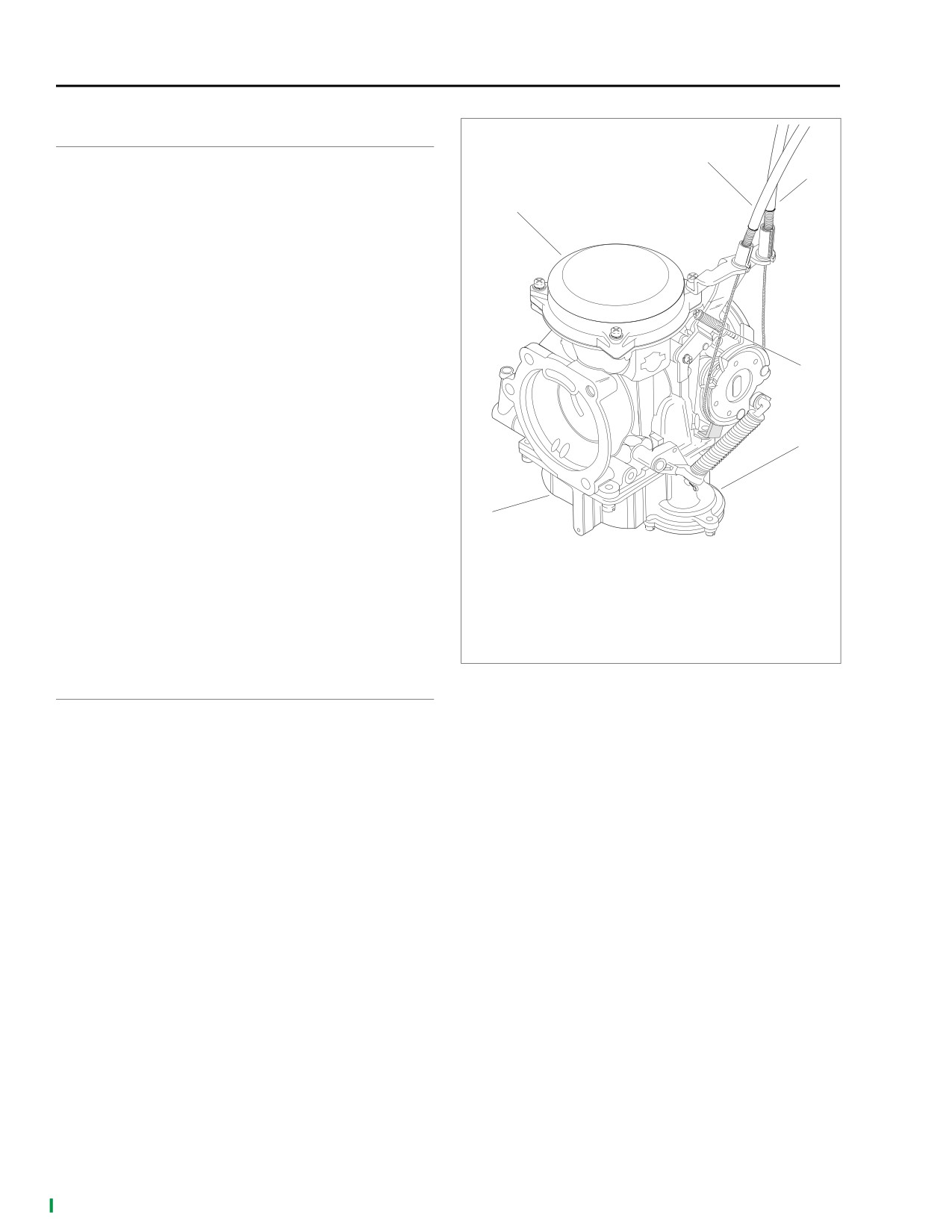
See Figure 4-2. The carburetor is a constant-velocity, gravity-
5
fed type with a float-operated inlet valve, a variable venturi, a
throttle stop screw (for idle speed adjustment) and a fuel
1
enrichment system (for starting).
Idle and transfer ports provide a balanced fuel mixture during
the transition period from stop to mid-range. A vacuum piston
controls venturi opening.
The carburetor is specifically designed to control exhaust
emissions. All jets are fixed. The idle mixture has been pre-
set at the factory. The idle mixture screw is recessed in the
carburetor casting. The opening is sealed with a plug
because it is intended that the idle mixture be non-adjustable.
4
NOTE
Adjusting mixture setting by procedures other than specified
in this section may be in violation of local regulations.
3
This system partially compensates for changes in the mixture
that are normally caused by changes in altitude. Because
atmospheric pressures drop as altitude increases, the pres-
sure difference in the upper and lower chambers is reduced;
2
this results in less fuel being delivered to the engine, thereby
maintaining the correct air/fuel ratio for better engine perfor-
mance and reduced exhaust emissions.
1.
Vacuum piston chamber
2.
Float chamber
The carburetor is equipped with an accelerator pump. The
3.
Accelerator pump
accelerator pump system uses sudden throttle openings
4.
Idle speed adjusting screw
(rapid accelerations) to quickly inject raw fuel into the carbu-
5.
Idle control cable
retor venturi; this provides extra fuel for smooth acceleration.
6.
Throttle control cable
Figure 4-2. Carburetor
ADJUSTMENT
Float Level
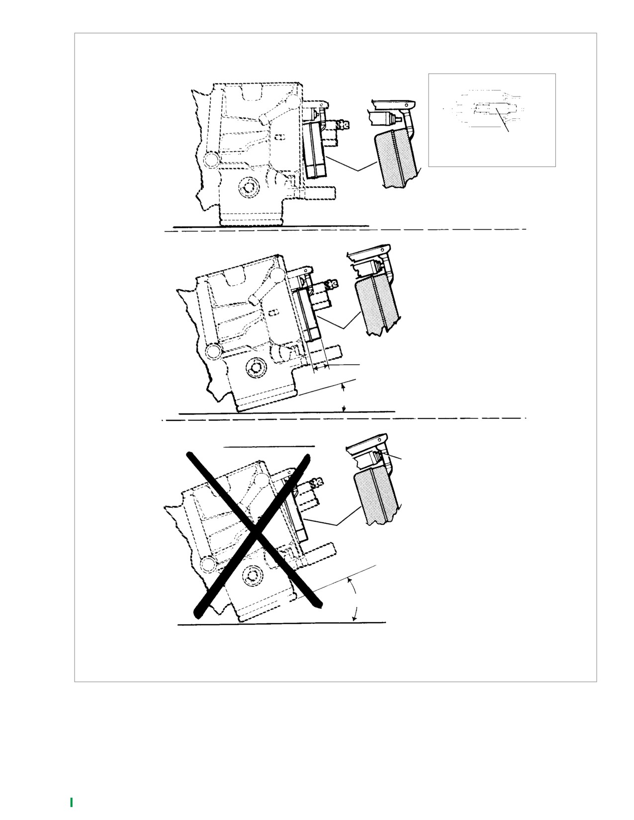
1.
See Figure 4-3. Place carburetor on a flat, clean surface
on engine manifold side. This is the “base.” Tilt carburetor
counterclockwise 15 to 20 degrees from base until float
comes to rest.
NOTE
If carburetor is tilted less than 15 degrees or more than 20
degrees, your measurements will be inaccurate.
2.
Use a vernier or dial caliper depth gauge to measure
from the carburetor flange face to the perimeter of the
float. Be careful not to push on float while measuring.
The measurement must be
0.413-0.453 in.
(10.49-11.51 mm). If measurement is not within given
dimension, remove float and carefully bend tab in order
to reposition float at proper level.
3.
Install float, and recheck setting.
4.
Install float bowl. Install carburetor as described in
INSTALLATION later in this section.
4-6
2006 Sportster: Fuel System
HOME
x0239x4x
Start float position
Pin
Fuel inlet valve
Float
“Base”
Correct float position
Float
0.413-0.453 in.
(10.49-11.51 mm)
15 to 20˚
Incorrect float position
Pin return
spring collapsed
Float
Greater than 20˚
Figure 4-3. Carburetor Float Adjustment
2006 Sportster: Fuel System
4-7
HOME
OPERATION CHECK: VACUUM
REMOVAL
PISTON
1WARNING
Opening Malfunction
Stop the engine when refueling or servicing the fuel sys-
tem. Do not smoke or allow open flame or sparks near
gasoline. Gasoline is extremely flammable and highly
1WARNING
explosive, which could result in death or serious injury.
While observing piston slide movement, be sure to main-
(00002a)
tain a safe distance from the carburetor and to wear suit-
1. Turn the fuel supply valve to OFF.
able eye protection. An unexpected engine backfire
2. Remove the air cleaner and backplate. See REMOVAL
could cause death or serious injury.
under 4.6 AIR CLEANER.
1.
See Figure 4-4. With air cleaner cover off and engine
running, twist throttle control partially open and closed
1WARNING
several times while observing whether or not vacuum
piston (6) has upward movement. If piston does not rise,
A small amount of gasoline may drain from the fuel hose
refer to Table 4-11. under 4.3 TROUBLESHOOTING.
when disconnected from the carburetor. Thoroughly wipe
2.
With engine not running, lift vacuum piston (6) with fin-
up any spilled fuel immediately and dispose of rags in a
ger. Feel whether piston lifts fully and smoothly or
suitable manner. Gasoline can be extremely flammable
whether there is a binding condition.
and highly explosive. Inadequate safety precautions may
result in death or serious injury.
Closing Malfunction
3. See Figure 4-4. Cut clamp (33) and disconnect fuel hose
1.
With engine not running, lift vacuum piston (6) to full
(34) from fuel inlet fitting (32).
open position, then release. Observe whether piston
4. Detach enrichener knob assembly from bracket between
slides downward smoothly and fully to stop.
cylinder heads. See
1.24 THROTTLE CABLES AND
2.
Observe position of piston slide at its lowest downward
ENRICHENER.
point. Lower edge of slide should rest at horizontal
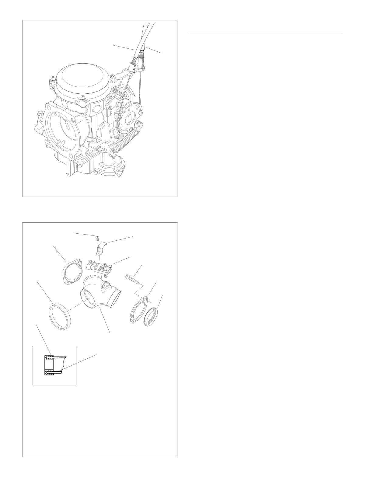
5. See Figure 4-5. Disconnect throttle cables (1, 2) from
groove at lower end of slide track. If problems are noted,
carburetor.
refer to Table 4-12. under 4.3 TROUBLESHOOTING.
6. See Figure 4-4. Disconnect fuel overflow/drain hose (19)
from fuel overflow fitting.
7. Remove enrichener cable assembly
(38,
39,
40),
enrichener valve (36) and spring (37).
8. On California models only, disconnect canister purge
hose from fitting on carburetor body. See 4.9 EVAPORA-
TIVE EMISSIONS CONTROL-CA MODELS.
9. Remove fuel tank. See REMOVAL under 4.8 FUEL
TANK.
10. See Figure 4-6. Pull carburetor free of intake manifold
(3). If removing intake manifold, remove four manifold
mounting screws (4). Remove intake manifold, seal ring
(1), mounting flanges (2,
5) and two intake manifold
seals (6).
11. If removing MAP sensor (7), remove screw (9), MAP
sensor clip (8) and MAP sensor.
4-8
2006 Sportster: Fuel System
HOME
x0240b4x
1.
Screw (3)
27.
Screw (4)
8
2.
Top cover
28.
Main jet
1
3
2
3.
Spring
29.
Needle jet holder
4.
Spring seat
30.
Needle jet
5.
Needle jet
31.
Carburetor body
6.
Vacuum piston
32.
Fuel inlet fitting
7.
Vacuum hose
33.
Clamp (2)
8.
Collar
34.
Hose
9.
Idle speed adj. screw
35.
Insulator
4
10.
Spring
36.
Enrichener valve
11.
Screw
37.
Spring
12.
Throttle cable bracket
38.
Starter cap
13.
Screw and lock washer
39.
Cable guide
14.
Pump rod
40.
Cable sealing cap
5
15.
Washer
41.
Collar
16.
Spring
42.
E-clip
17.
Collar
43.
Washer
18.
O-ring
44.
Cotter pin (2)
6
19.
Fuel overflow/drain hose
45.
Accelerator pump rod
20.
Clip
46.
Boot
21.
Diaphragm
47.
Drain screw
40
7
22.
Diaphragm spring
48.
O-ring
39
23.
Pump housing
49.
Fuel inlet valve w/clip
24.
Screw w/washer (3)
50.
Float
38
25.
O-ring
51.
Accelerator pump
26.
Float chamber
nozzle
52.
Overflow pipe
53.
Pin
12
54.
Washer
11
37
35
55.
Slow jet
33
9
10
56.
Washer
34
36
57.
Lever
33
13
avid
41
y
D
rle
a
H
32
14
56
44
31
57
55
15
43
53
45
54
50
16
30
46
51
52
44
42
17
49
29
47
18
28
48
21
19
27
20
22
26
23
25
24
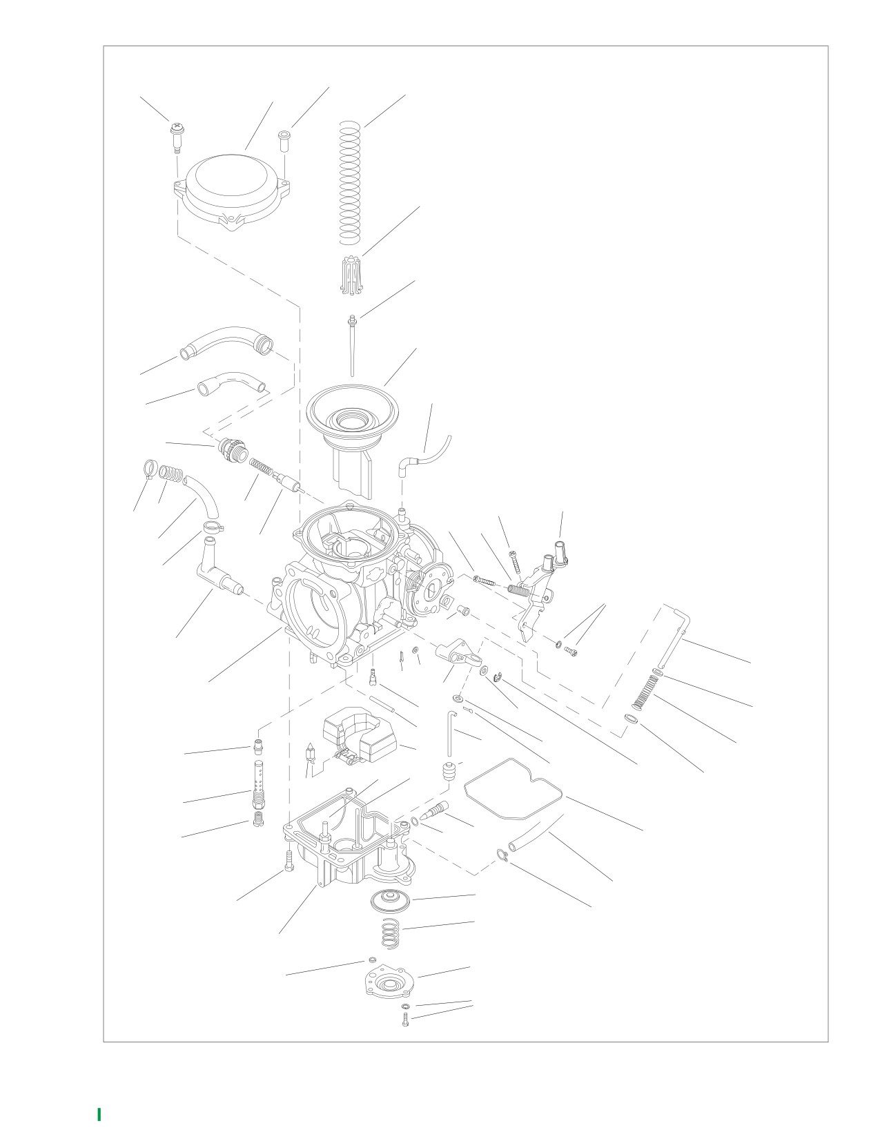
Figure 4-4. Constant-Velocity (CV) Carburetor
2006 Sportster: Fuel System
4-9
HOME
x0506a1x
DISASSEMBLY
1
Vacuum Piston Chamber
2
1. See Figure 4-4. Remove screws (11, 13) and throttle
cable bracket (12).
2. Remove three screws (1). Remove top cover (2) and
spring (3).
3. Lift out vacuum piston (6) with needle jet (5) and spring
seat (4). Remove loose parts from vacuum piston.
Carburetor Body
1. See Figure 4-4. Remove four screws (27). Remove float
chamber assembly (26).
2. Remove pin (53), float (50) and fuel inlet valve assembly
(49).
3. Unscrew main jet (28) and needle jet holder (29). Needle
jet (30) is free to be removed from bottom end of pas-
sage.
4. Insert thin-bladed screwdriver into slow jet passage to
remove slow jet (55).
1.
Throttle control cable
2.
Idle control cable
Accelerator Pump
Figure 4-5. Throttle Cables
1. See Figure 4-4. Remove three screws with lock washers
(24), accelerator pump housing (23), spring (22) and dia-
phragm (21).
x0241a4x
2. Remove O-ring (25) from housing.
9
8
2
7
4
1
5
6
1
3
3
x0246a4x
1.
Seal ring
2.
Rear mounting flange
3.
Intake manifold
4.
Screw (4)
5.
Front mounting flange
6.
Intake manifold seal (2)
7.
MAP sensor
8.
MAP sensor clip
9.
Screw
Figure 4-6. Intake Manifold
4-10
2006 Sportster: Fuel System
HOME
CLEANING, INSPECTION AND
ASSEMBLY
REPAIR
Vacuum Piston Chamber
Vacuum Piston Components
1. See Figure 4-4. Place needle jet (5) through center hole
in vacuum piston (6). Place spring seat (4) over top of
1.
See Figure 4-4. Hold vacuum piston (6) up to strong
needle jet.
light. Examine diaphragm at top of vacuum piston for evi-
2. Insert vacuum piston into carburetor body
(31). The
dence of pinching, holes or tears. Replace if damaged.
slides on the piston are off-center and the piston will fit
2.
Examine vacuum passage through bottom of piston.
into the slide track grooves one way only. If piston does
Clean passage if restricted.
not fit, rotate 180 degrees.
3.
Examine spring (3) for stretching, crimping, distortion or
3. Check to be sure vacuum piston diaphragm is seated
damage. Replace if necessary.
evenly into groove at top of carburetor body. Place spring
4.
Examine slide on sides of piston to be sure surface is
(3) over spring seat, and carefully lower top cover (2).
smooth and clean. Clean or buff out any rough surfaces.
Keep spring straight while lowering top cover.
5.
Examine needle jet (5) for evidence of bending or dam-
4. After top cover is seated, hold top cover while lifting vac-
age. Needle should be straight; surface of taper should
uum piston upward. Piston should rise to top smoothly. If
be smooth and even.
piston movement is restricted, spring is cocked; lift up top
cover, then lower carefully, keeping spring coils straight.
Carburetor Body Components
5. Once top cover is installed correctly, install three screws
1.
See Figure 4-4. Check float chamber O-ring (18) for any
(1). Place throttle cable bracket (12) in position with idle
distortion or damage. Replace if seating surfaces are
screw (9) resting on top of throttle cam stop. Install body
damaged.
screw and washer (13) first, then top screw (11) to pre-
vent bending bracket or throttle cam.
2.
Examine fuel inlet valve (49) and inlet valve seat. Clean
with carburetor cleaner. Replace valve and/or carburetor
Carburetor Body
body (31) if seating surfaces are damaged.
3.
Clean slow jet (55) with carburetor cleaner. Check to be
sure all orifices are open.
CAUTION
4.
Check enrichener valve (36). Be sure needle guide is
Slow jets from fixed-venturi carburetors look the same as
clean, straight and undamaged. Check composition seat-
the slow jet of the CV carburetor. However, the air bleed
ing surface for wear or damage. Replace if damaged.
hole sizes are different on fixed-venturi carburetors, and
5.
Check enrichener valve chamber in carburetor body.
they must not be installed on CV carburetors.
Clean with carburetor cleaner. Check that all passages
1. See Figure 4-4. Thread slow jet (55) into slow jet pas-
are open and free of obstruction.
sage in carburetor body (31) with narrow-bladed screw-
6.
Clean needle jet (30). Replace if damaged.
driver.
7.
Clean all internal fuel/air passages and jets. Check that
2. Turn carburetor upside down. Place needle jet (30) in
all passages and jets are open and free of obstruction.
main jet passage with needle passing through center
8.
Check needle jet holder (29). Clean bleed tube orifices.
hole. Be sure end of jet with larger opening and cham-
Replace holder if damaged.
fered surface enters passage first.
9.
Check float (50) for cracks or other leaks. Replace if
3. Insert needle jet holder (29) into main jet passage with
damaged.
needle inserted into center of holder. Thread holder into
passage and tighten. Thread and tighten main jet (28) in
10. Clean main jet (28) with carburetor cleaner and inspect
tapped hole in holder.
for damage. Replace if damaged.
4. Place float assembly (50) into position with fuel inlet
Accelerator Pump
valve (49) inserted into valve seat in carburetor body and
pivot arm aligned with holes in mounting posts (at bottom
1.
See Figure 4-4. Inspect the accelerator pump diaphragm
of carburetor body). Insert pin (53) through float pivot
(21) for holes, cracks or deformation. Replace as neces-
arm and float mounting posts.
sary.
5. Check float level setting and adjust if necessary. See
2.
Replace the pump rod (45) if it is bent; replace the boot
Float Level under 4.5 CARBURETOR ADJUSTMENT.
(46) if it is cracked.
6. Place float chamber assembly (26) over float and onto
carburetor body flange. Chamber will only fit in one posi-
tion. Install and tighten screws (27).
Accelerator Pump
See Figure 4-4. Install diaphragm (21), spring (22), O-ring
(25) and pump housing (23). Secure with three screws and
lock washers (24).
2006 Sportster: Fuel System
4-11
HOME
INSTALLATION
Carburetor Fuel Overflow/Drain Hose
Routing
See Figure 4-4. On non-California models, route fuel over-
Carburetor
flow/drain hose (19) from the carburetor fuel overflow fitting
1.
See Figure 4-6. If MAP sensor (7) was removed from
downward and rearward through the space between the
intake manifold (3), install MAP sensor and MAP sensor
engine rear cylinder and the rear cylinder push rod covers
clip (8). Secure with screw (9).
(intake and exhaust), and then downward through the space
between the engine crankcase and the gear cover.
2.
Place flanges (2, 5) onto intake manifold.
3.
Place intake manifold seals (6) onto each spigot of mani-
On all California models, route the fuel overflow/drain (vent)
fold with chamfered edge against flanges.
hose from the carburetor fuel overflow fitting, under the car-
buretor float chamber, to a plastic fitting on the inboard side of
4.
Place channel of seal ring (1) over inlet end of manifold.
the air cleaner backplate. Connect canister purge hose onto
5.
Position manifold against intake ports of cylinder head,
fitting on carburetor body. See
4.9 EVAPORATIVE EMIS-
with slotted and round holes in flanges aligned with holes
SIONS CONTROL-CA MODELS and INSTALLATION under
in cylinder head. Insert screws through manifold flanges
4.6 AIR CLEANER.
and loosely thread into tapped holes in cylinder head.
NOTE
The fit between the carburetor and the seal ring is tight. For
ease of installation, lubricate the mating surfaces, carburetor
body and seal ring with liquid dish soap or tire mounting lube
prior to assembly.
6.
Lubricate only the inside surface of seal ring that will be
in contact with the carburetor. Also apply a light coat of
lubricant to the spigot of the carburetor body. Push car-
buretor body into seal ring.
7.
Install air cleaner backplate and air cleaner assembly.
See INSTALLATION under 4.6 AIR CLEANER.
8.
See Figure 4-6. Final tighten intake manifold screws to
96-144 in-lbs (10.9-16.3 Nm).
9.
Install fuel tank. See INSTALLATION under 4.8 FUEL
TANK.
10. On California models only, connect canister purge hose
onto fitting on carburetor body. See 4.9 EVAPORATIVE
EMISSIONS CONTROL-CA MODELS.
11. See Figure 4-4. Connect fuel overflow/drain hose (19) to
fuel overflow fitting. Secure with clip (20).
12. Connect vacuum hose (7) to fitting on carburetor body.
13. Install enrichener valve
(36) and spring
(37). Install
enrichener cable assembly (38, 39, 40).
14. See Figure 4-5. Install throttle cables.
15. See Figure 4-4. Install fuel hose (34) onto fuel inlet fitting
(32). Secure with new clamp (33).
4-12
2006 Sportster: Fuel System
HOME
AIR CLEANER
4.6
REMOVAL
CAUTION
1.
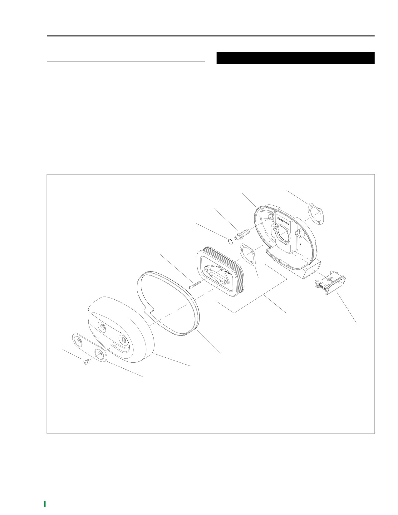
See Figure 4-7. Remove two screws (1) and trim insert
Install air filter before running engine. Failure to do so
(2) from air cleaner cover (3).
can draw debris into the engine and could result in
2.
Remove air cleaner cover from air cleaner backplate
engine damage. (00207a)
(10). Remove air cleaner seal (4) from air cleaner cover.
4. Remove two breather screws (9) from air cleaner back-
3.
Remove three screws (5). Remove air filter element (6)
plate.
and gasket (7) from air cleaner backplate. Discard gas-
5. Remove air cleaner backplate and gasket (11). See Fig-
ket. If filter element is being removed for cleaning only,
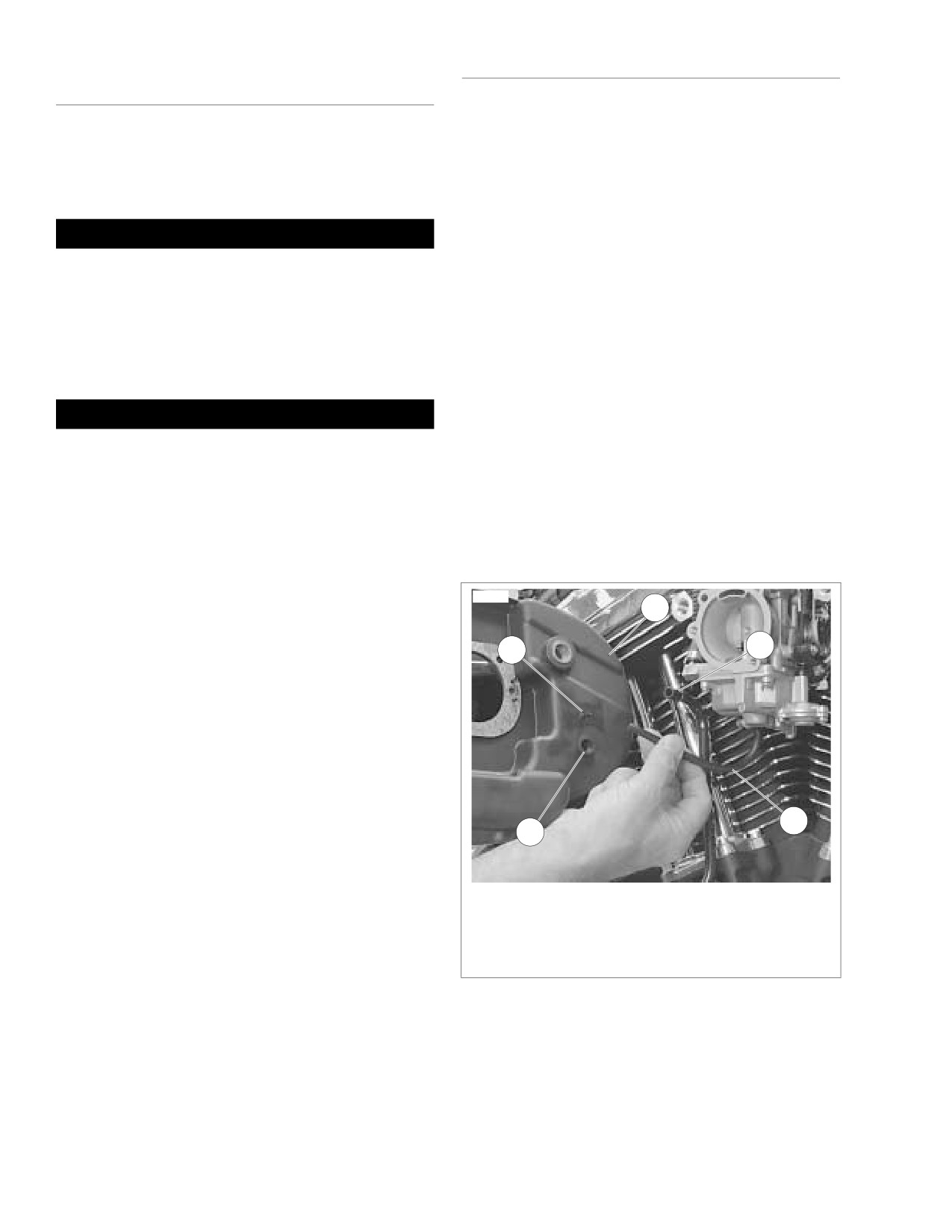
ure 4-8. On California models, disconnect clean air inlet
proceed to CLEANING, INSPECTION AND REPAIR
hose (2) and carburetor overflow (vent) hose (1) from air
under 4.6 AIR CLEANER.
cleaner backplate assembly (3).
6. See Figure
4-7. If snorkel insert
(12) needs to be
repaired or replaced, remove it from air cleaner back-
plate.
x0242a4x
10
11
9
8
5
7
6
12
1
4
3
2
1.
Screw (2)
7. Gasket
2.
Trim insert
8. O-ring (2)
3.
Air cleaner cover
9. Breather screw (2)
4.
Air cleaner seal
10. Air cleaner backplate
5.
Screw (3)
11. Carburetor intake gasket
6.
Air filter element (includes item 7)
12. Snorkel insert
Figure 4-7. Air Cleaner Assembly
2006 Sportster: Fuel System
4-13
HOME
CLEANING, INSPECTION AND
INSTALLATION
REPAIR
1.
See Figure 4-8. On California models, connect carbure-
tor overflow (vent) hose (1), and clean air inlet hose (2) to
1.
See Figure 4-7. Thoroughly clean air cleaner backplate
air cleaner backplate assembly (3).
(10) and inside of air cleaner cover (3).
2.
See Figure 4-7. If snorkel insert (12) was removed from
2.
If air filter element (6) is damaged or if filter media cannot
air cleaner backplate, slide insert into air cleaner back-
be adequately cleaned, replace element and proceed to
plate and snap into place.
step 6.
3.
Position new gasket (11) and air cleaner backplate (10)
at carburetor air inlet. Secure air cleaner backplate to
1WARNING
engine heads with two breather screws (9). Tighten to
84-120 in-lbs (9.5-13.6 Nm).
Do not use gasoline or solvents to clean filter element.
Flammable cleaning agents can cause an intake system
4.
Apply a thin coat of engine oil or light grease to O-rings
fire, which could result in death or serious injury.
(8). This will help prevent them from being damaged
(00101a)
when air filter element is installed.
5.
Position new gasket (7) on air cleaner backplate. Make
3.
Wash air filter element thoroughly in warm, soapy water.
sure gasket holes are lined up with backplate holes.
To remove soot and carbon, soak air filter element for 30
minutes in warm water with mild detergent.
6.
Install air filter element (6) onto backplate. Secure with
three screws (5). Tighten to 40-60 in-lbs (4.5-6.8 Nm).
1WARNING
7.
Install air cleaner seal (4) on air cleaner cover (3). To
ensure proper sealing, make sure air cleaner seal covers
Compressed air can pierce the skin and flying debris
the entire edge of the air cleaner cover.
from compressed air could cause serious eye injury.
8.
Install air cleaner cover onto backplate. Make sure air
Wear safety glasses when working with compressed air.
cleaner seal fits inside backplate and is not pinched or
Never use your hand to check for air leaks or to deter-
distorted.
mine air flow rates. (00061a)
9.
Install trim insert
(2) and secure with two screws (1).
4.
Dry air filter element using low-pressure (32 psi/221 kPa
Tighten to 36-60 in-lbs (4.1-6.8 Nm).
maximum) compressed air. Rotate air filter element while
moving air nozzle up and down filter element interior. Do
not tap air filter element on hard surface.
10503
5.
Hold air filter element up to strong light source. Element
3
can be considered sufficiently clean if light is uniformly
visible through filter material.
2
4
6.
Examine O-rings (8). If damaged, replace with new O-
ring(s).
7.
Examine air cleaner seal (4). If cracked, torn or other-
wise damaged, replace with new seal.
8.
Repair or replace snorkel insert (12) as necessary.
NOTE
On California models, a gravity operated trap door in the air
cleaner’s snorkel is closed when the engine is not running, to
seal the inlet port of the air cleaner backplate. This prevents
1
5
hydrocarbon vapors emanating from the carburetor throat
and from the float bowl overflow (vent) hose from escaping
into the atmosphere. When the vehicle is running, engine
vacuum holds the trap door open.
1.
Carburetor overflow (vent) hose
2.
Clean air inlet hose (from charcoal canister)
9.
On California models, open the trap door in the snorkel
3.
Air cleaner backplate assembly
with a finger, then release. Observe the trap door to
4.
Overflow (vent) hose port
make sure it closes smoothly and completely, without
5.
Clean air inlet hose port
binding.
Figure 4-8. Air Cleaner Backplate Hose
Connections (CA Models)
4-14
2006 Sportster: Fuel System
HOME
FUEL SUPPLY VALVE
4.7
GENERAL
x0509a1x
1
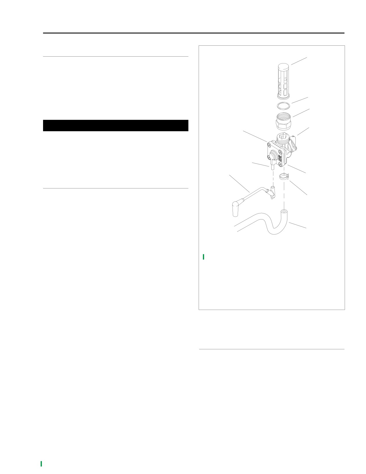
See Figure 4-9. The fuel supply valve (8) is located under the
left side of the fuel tank. The fuel supply to the carburetor is
turned off when the handle (9) is in the horizontal position.
Turning the handle up to the vertical position turns on the
main supply. Turning the handle down to the vertical position
turns on the reserve supply. The valve is vacuum-operated
2
and will open and close when the engine is turned ON or
3
OFF.
CAUTION
9
8
The fuel supply valve should be turned off when the
engine is not running. If the fuel supply valve is not
turned off when the engine is not running, it is possible
for fuel to drain into the engine, dilute the engine oil and
4
cause engine damage.
10
5
OPERATION
The fuel supply to the carburetor is controlled by the valve
6
handle positions and an internal vacuum operated valve. No
fuel will flow through the valve until the following conditions
are met:
1.
Handle must be in ON or RES position.
7
2.
A vacuum of approximately 0.5-1.0 in. (12.7-25.4 mm) of
Mercury (Hg) must be applied to the vacuum nipple.
1.
Fuel valve filter
NOTE
2.
Gasket
In service, the vacuum nipple is connected to the carburetor.
3.
Hex fitting
When the engine is running, a vacuum is present at the nip-
4.
Vacuum nipple
ple.
5.
Fuel outlet nipple (underneath)
6.
Clamp
7.
Fuel supply hose
8.
Fuel supply valve assembly
9.
Fuel valve handle
10.
Vacuum hose
Figure 4-9. Fuel Supply Valve Assembly
REMOVAL, INSPECTION AND
INSTALLATION
See 1.26 FUEL SUPPLY VALVE FILTER for procedures relat-
ing to removal, inspection and installation of the fuel supply
valve.
2006 Sportster: Fuel System
4-15
HOME
TROUBLESHOOTING
Refer to Table 4-13. For vacuum testing information, see
below.
Table 4-13. Troubleshooting Fuel Supply Valve
PROBLEM
CAUSE
SOLUTION
Vacuum hose not connected to vacuum
Connect hose to vacuum nipple.
nipple. See Figure 4-9.
Vacuum valve not opening.
Leaking diaphragm.
Replace entire valve assembly.
Vacuum hose assembly pinched or
Replace vacuum hose assembly.
cracked.
Damaged sealing surface on valve side
Replace entire valve assembly.
Vacuum valve does not close.
of diaphragm.
Broken or missing internal spring.
Replace entire valve assembly.
Leaking diaphragm.
Replace entire valve assembly.
Valve leaks gasoline at bottom nipple.
Loose diaphragm housing screws.
Tighten screws.
Vacuum Test
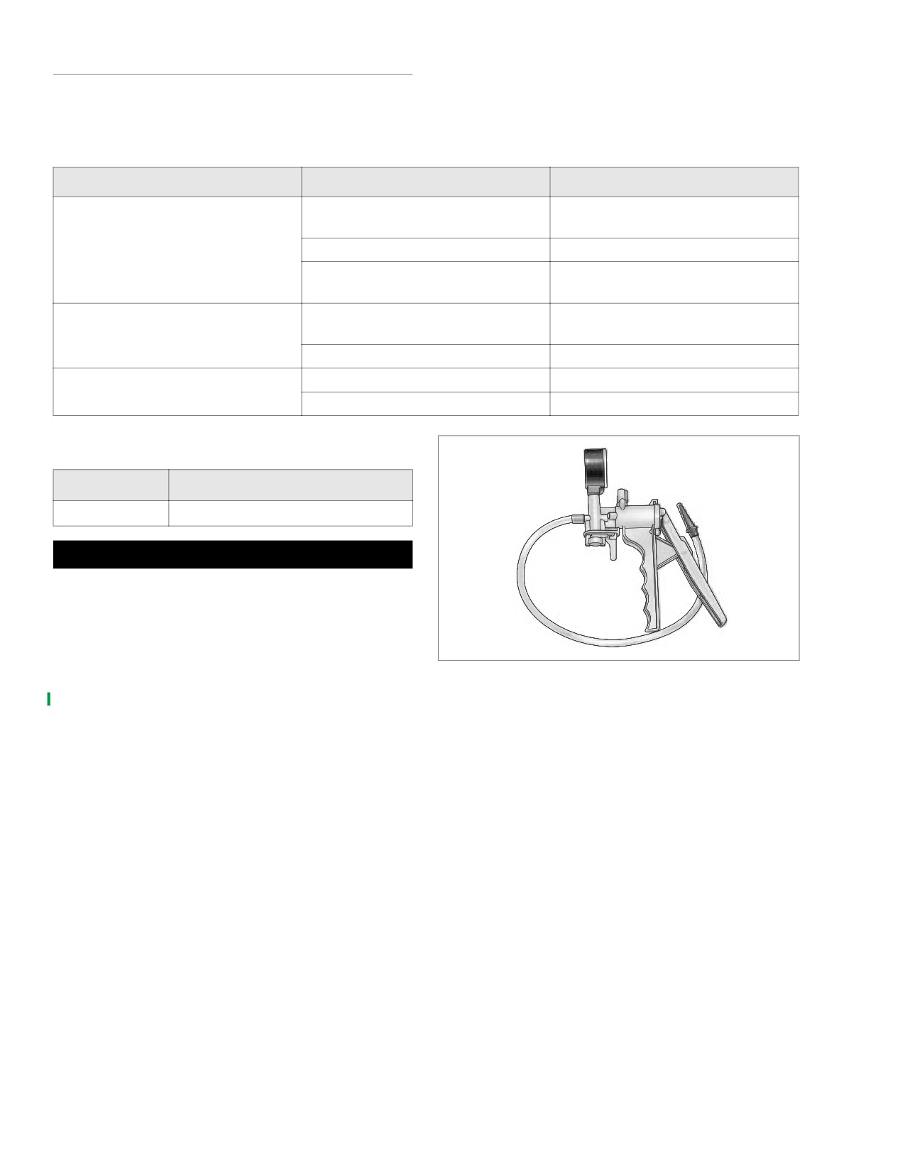
d0108a1x
PART NO.
SPECIALTY TOOL
HD-23738-A
Plastic Mity-vac® Hand Pump
1WARNING
Stop the engine when refueling or servicing the fuel sys-
tem. Do not smoke or allow open flame or sparks near
gasoline. Gasoline is extremely flammable and highly
explosive, which could result in death or serious injury.
(00002a)
Vacuum test the valve using the procedure below:
Figure 4-10. Mity-Vac Hand Pump
1.
Connect PLASTIC MITY-VAC® HAND PUMP, vacuum
line and suitable vacuum fitting to the vacuum port of the
fuel supply valve.
2.
Run a section of clear fuel line from the fitting on the fuel
supply valve to a gas can.
3.
Pull 25 in. Hg vacuum and release. Check for fuel flow
while applying vacuum and check that fuel stops flowing
shortly after vacuum is released.
4. Repeat step 3 five times, each time checking for fuel
flow at vacuum and no fuel flow shortly after vacuum is
released. On fifth application of vacuum, pause with vac-
uum applied, and check for slow leaks. Release vacuum.
5.
If no leaks were present, go to next step. If leaks were
present, repeat replacement procedure.
6.
Disconnect hand held vacuum pump and fuel line.
7.
Position new hose clamp on fuel hose and install fuel
hose to outlet fitting on valve body.
8.
Install vacuum hose to valve nipple.
4-16
2006 Sportster: Fuel System