Harley Davidson 2006 Sportster XLH MODELS. Service Manual - page 13
HOME
6.
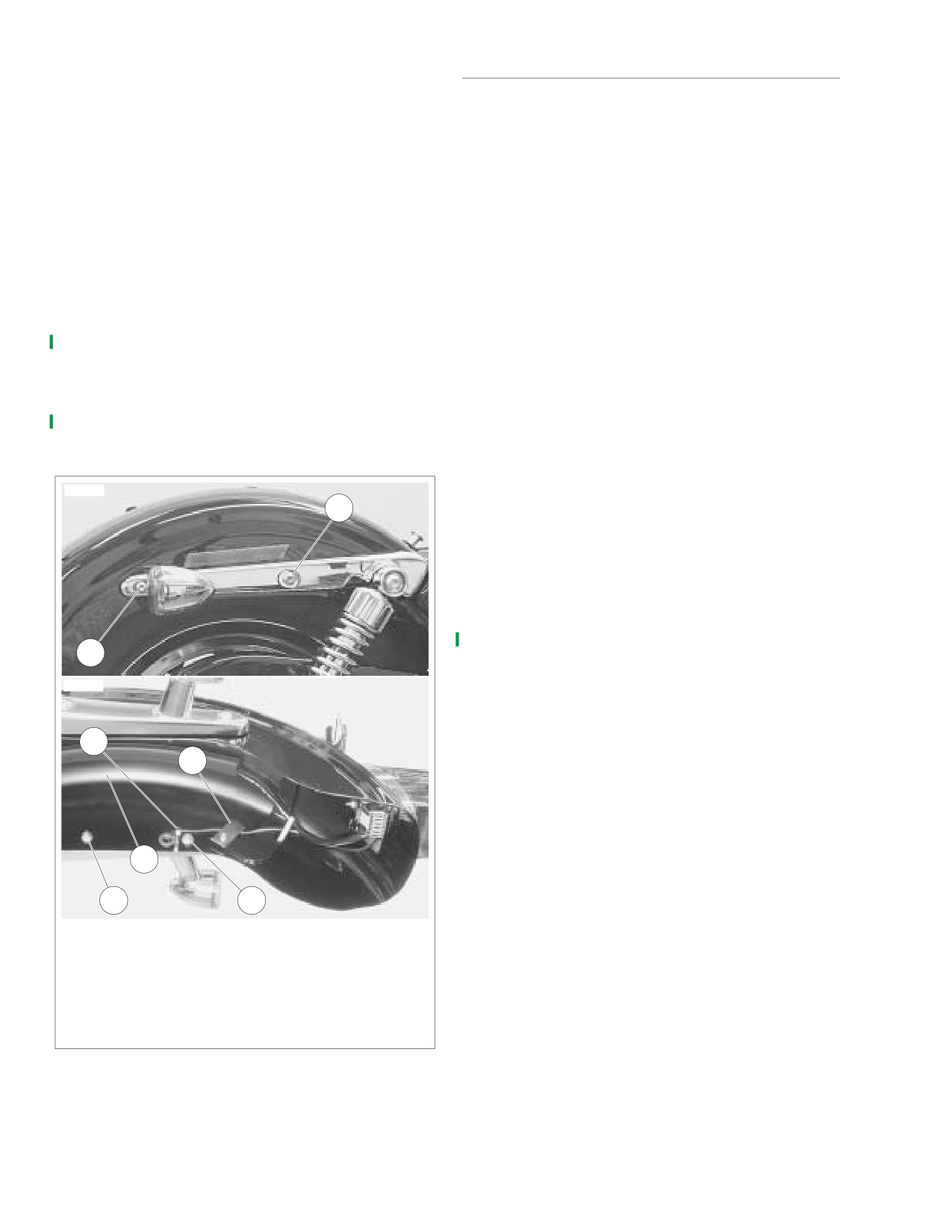
See Figure 2-159. Remove rear turn signal stalk nuts (1)
INSTALLATION
from inside rear fender on both sides.
7.
Remove forward fender support screw with washer (2)
NOTE
and nut (4), and aft fender support screw with washer (3)
If a new fender is being installed, complete steps 1-7. Other-
and nut plate (5) on both sides.
wise proceed directly to step 8.
8.
Pull turn signal wiring harnesses through holes in tail
1.
See Figure 2-156. Remove three screws (3), three nuts
lamp base and rear fender. Disengage turn signal wiring
(4) and one washer (5) securing license plate bracket
harnesses from wire retention brackets (6).
assembly (2) and rear fender brace (25) to old fender (1).
9.
See Figure 2-156. Remove rear fender strut covers (21)
Position assembly on new fender and secure with
with attached turn signal assemblies
(16) from rear
screws, nuts and washer. Align remaining holes in rear
fender struts.
fender brace with aft fender support screw holes in
10. Remove screw (13), seat post (14) and flat washer (15)
fender. Tighten license plate bracket mounting screws to
to detach top of rear fender (1) from frame cross member
20-25 in-lbs (2.3-2.8 Nm).
tab.
2.
Carefully drill out pop rivets securing rear fender exten-
11. Carefully remove rear fender with attached tail/brake
sion (26) to old fender with a 1/4-in. (6.35 mm) diameter
lamp assembly from motorcycle.
drill bit. Rivet rear fender extension to new fender.
12. See Figure 2-157. Depress latch on rear lighting power
3.
Carefully drill out pop rivets securing wire retention
connector [94] (3) and unplug connector from rear light-
brackets (28) to old fender with a 1/4-in (6.35 mm) diam-
ing circuit board.
eter drill bit. Rivet brackets to new fender.
13. Remove screw with washer (5) and lift tail/brake lamp
4.
Remove fender seat nut kit (24) from old fender and
base from fender.
install on new fender.
5.
Place fender upside down on clean, soft towel or mat to
protect the finish. Clean inside area of fender where wir-
10506
ing harness/conduit will be placed, with a mixture of alco-
2
hol and water. Allow to air-dry thoroughly.
6.
Position new wire harness and conduit inside fender at
the same approximate position where harness/conduit
assembly is located in old fender. Insert end of wiring
harness with ‘D’ plug through ‘D’ hole in front of fender.
Insert plug into hole.
7.
Slide conduit toward ‘D’ plug as far as it will go. Insert
other end of wiring harness through tail lamp housing
3
hole in rear of fender. Remove adhesive tape backing
from conduit and press conduit in place along right side
10507
curve of fender.
8.
Carefully install rear fender onto motorcycle. Align holes
in fender with those in struts. Temporarily install screws
6
(18, 20) through fender struts and fender to hold fender
5
in place. Route rear lighting harness connector
[7B]
between frame cross member and top of oil tank. Plug
connector into socket [7A].
7
4
1
1.
Rear turn signal stalk nut (2)
2.
Forward fender support screw with washer (2)
3.
Aft fender support screw with washer (2)
4.
Forward fender support nut (2)
5.
Aft fender support nut plate (2)
6.
Wire retention bracket
7.
Rear lighting wiring harness and conduit
Figure 2-159. Rear Fender, Strut Cover and
Turn Signal Lamp Assembly
2-110
2006 Sportster: Chassis
HOME
9.
See Figure 2-158. Secure ICM (2) to studs on frame with
17. Insert tail lamp connector [93] (4) in tail lamp base socket
lock nuts (1). Tighten to 12-20 in-lbs (1.4-2.3 Nm).
as shown. See Figure 2-156. Screw tail lamp socket (9)
into lens (7). Attach tail lamp lens (7) to base (11) with
10.
See Figure 2-156. Secure front of fender with screw (13),
two screws (6).
washer (15) and seat post (14). Finger-tighten screw
only, at this time.
18. Open left side cover and install Maxi-Fuse. Close left
side cover. See 7.25 MAXI-FUSE.
11.
Remove screws from right side of fender that were tem-
porarily installed in step 8. Install right side rear fender
strut cover (21) with attached turn signal assembly to
1WARNING
fender strut. Push turn signal wiring harness through
appropriate hole in strut and fender. Install nut (22) onto
Check for proper tail lamp operation before riding motor-
cycle. Visibility is a major concern for motorcyclists.
turn signal stalk (17) from inside fender. Finger-tighten
Improper tail lamp operation may lead to an accident
only at this time.
which could result in death or serious injury.
12.
Secure fender to strut with screw (20), washer (19) and
nut (22) in forward mounting hole. Install screw (18),
19. Turn ignitions switch ON and check rear lighting.
washer (19) and nut plate (23) in aft mounting hole. Fin-
a. Make sure tail lamp is lit.
ger-tighten screws only at this time.
b. Depress turn signal switches and make sure both
13.
Repeat steps 11. and 12. on left side of fender.
turn signals are operating properly.
14.
Now tighten all fender mounting hardware in the follow-
c. Operate front or rear brake and make sure brake
ing sequence:
lamp illuminates.
a. Tighten screw (13) and seat post (14) to 96-156 in-
lbs (10.9-17.6 Nm).
1WARNING
b. Tighten turn signal stalk nuts to
132-216 in-lbs
After installing seat, pull upward on front of seat to be
(14.9-24.4 Nm).
sure it is in locked position. While riding, a loose seat can
c. Tighten screws (18, 20) to 132-216 in-lbs (14.9-
shift causing loss of control, which could result in death
24.4 Nm).
or serious injury. (00070a)
15.
Install tail lamp base (11) to fender with screw (10) and
20. Install seat. See INSTALLATION under 2.32 SEAT.
clip nut (12). Tighten screw to 45-48 in-lbs (5.1-5.4 Nm).
16.
See Figure 2-157. Push 6-pin Amp connector [94] (3)
and left [18] (1) and right [19] (2) turn signal connectors
through access holes in tail lamp base and connect as
shown.
2006 Sportster: Chassis
2-111
HOME
BELT GUARD AND DEBRIS DEFLECTOR
2.30
REMOVAL
x0578b2x
Belt Guard
4
1
1.
See Figure
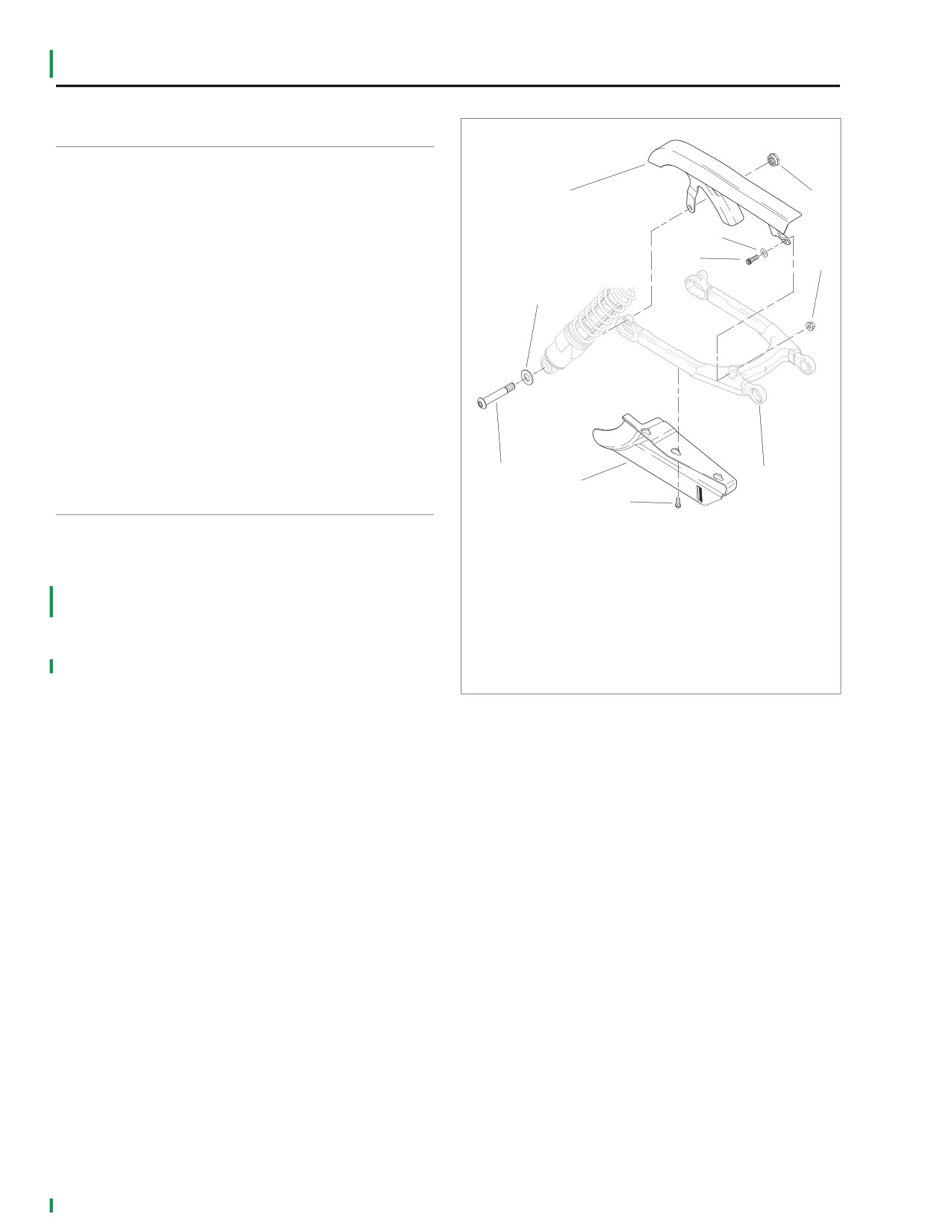
2-160. Unthread right side lower shock
absorber mount nut (1). Pull shock absorber mounting
6
bolt (2) out slightly until it clears mounting hole in belt
guard (4).
5
7
2.
Remove screw (5), washer (6) and nut (7) securing front
3
of belt guard to rear fork (10).
3.
Remove belt guard from vehicle.
Debris Deflector
1.
See Figure 2-160. Loosen, but do not remove, three
screws with captive washers (9) securing debris deflec-
tor (8) to underside of rear fork (10).
2.
Slide debris deflector forward until keyway slots in deflec-
tor clear screw heads. Remove debris deflector.
2
10
8
INSTALLATION
9
1.
Nut
2.
Screw
Belt Guard
3.
Washer
1.
See Figure 2-160. Slide belt guard (4) into place on vehi-
4.
Belt guard
cle. Tab on front of belt guard mounts outboard of mount-
5.
Screw
ing bracket on rear fork.
6.
Washer
7.
Nut
2.
Secure front of belt guard to rear fork (10) with screw (5),
8.
Debris deflector
washer (6) and nut (7). Tighten to 120-180 in-lbs (13.6-
9.
Screw with captive washer (3)
20.4 Nm).
10. Rear fork
3.
Push lower shock absorber mounting screw (2) through
rear belt guard mounting hole. Thread nut (1) on screw.
Figure 2-160. Belt Guard/Debris Deflector
Tighten to 45-50 ft-lbs (61.1-67.9 Nm).
Debris Deflector
1.
See Figure 2-160. Position debris deflector (8) in place
on underside of rear fork (10).
2.
Fit large end of keyway slots in deflector over screw
heads and captive washers (9). Slide deflector rearward
to lock screws in slots. Tighten screws to 36-60 in-lbs
(4.1-6.8 Nm).
2-112
2006 Sportster: Chassis
HOME
JIFFY STAND
2.31
GENERAL
WARNING
1
The vehicle is equipped with a jiffy stand (or side stand) that
Always park motorcycle on a level, firm surface. An
locks when placed in the full forward position (down) with the
unbalanced motorcycle can fall over, which could result
full weight of the vehicle resting on it.
in death or serious injury. (00039a)
1WARNING
1WARNING
The jiffy stand locks when placed in the full forward
Be sure jiffy stand is fully retracted before riding. If jiffy
(down) position with vehicle weight on it. If the jiffy stand
stand is not fully retracted, it can contact the road sur-
is not in the full forward (down) position with vehicle
face causing a loss of vehicle control, which could result
weight on it, the vehicle can fall over which could result
in death or serious injury. (00007a)
in death or serious injury. (00006a)
10129
1
2
5
4
3
3
6
7
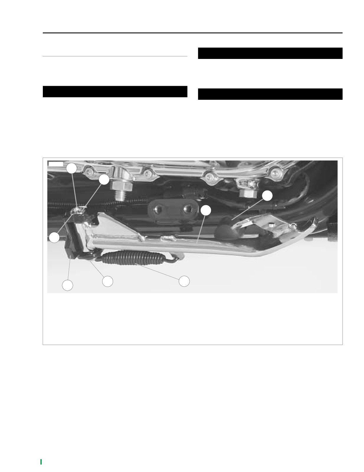
1.
Clevis pin
2.
Cotter pin
3.
Bushing (2)
4.
Jiffy stand leg
5.
Rubber bumper
6.
Spring
7.
Jiffy stand yoke
Figure 2-161. Jiffy Stand (Retracted Position)
2006 Sportster: Chassis
2-113
HOME
REMOVAL
INSTALLATION
1WARNING
1WARNING
Wear gloves and protective eyeglasses (or face shield)
Wear gloves and protective eyeglasses (or face shield)
when performing the following procedure. The jiffy stand
when performing the following procedure. The jiffy stand
spring tension could cause the spring, attached compo-
spring tension could cause the spring, attached compo-
nents and/or hand tools to fly outward at great speed and
nents and/or hand tools to fly outward at great speed and
could cause death or serious injury.
possibly cause death or serious injury.
1.
Block motorcycle under frame so that motorcycle is
1.
Clean and lubricate jiffy stand components according to
securely upright and jiffy stand may be moved through its
procedure listed in CLEANING AND LUBRICATION
full range of travel.
above.
2.
See Figure 2-161. Remove rubber bumper (5) from
2.
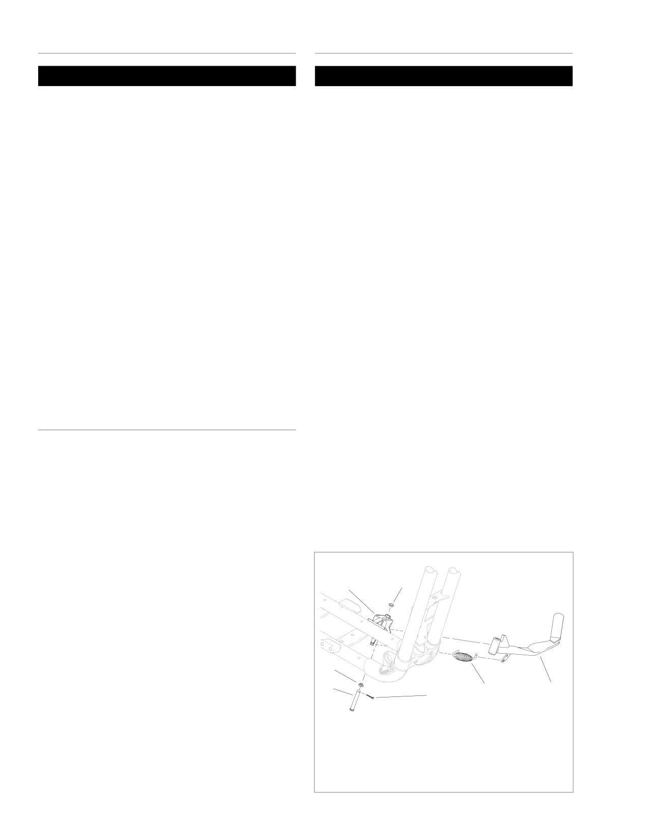
See Figure 2-162. Hook either end of spring (6) into
frame to permit further retraction of jiffy stand leg (4).
spring mounting hole on jiffy stand leg (5). Install other
Additional spring tension relief allows for easier spring
end of spring over frame mounted anchor pin.
removal.
3.
While holding end of spring in groove of anchor pin and
3.
Place jiffy stand leg in retracted position. Remove and
holding jiffy stand leg in its retracted position, position
discard cotter pin (2).
pivot end of jiffy stand leg within yoke (4) on motorcycle
frame. Insert clevis pin (1) through lower pivot hole of
4.
See Figure 2-162. While firmly holding jiffy stand leg (5)
yoke and halfway into pivot hole of jiffy stand leg.
in fully retracted position, withdraw clevis pin (1) until it
disengages with the upper pivot hole of jiffy stand yoke
4.
See Figure 2-161. Lift jiffy stand leg (4) upward, aligning
(4).
pivot hole of jiffy stand leg with slotted upper hole of yoke
(7). With shoulder down, position bottom bushing (3),
5.
Detach spring (6) from anchor pin using pliers. Unhook
over clevis pin (1). Insert clevis pin through holes in jiffy
other end of spring from jiffy stand leg.
stand leg and yoke.
6.
Remove clevis pin from lower pivot hole of jiffy stand
5.
Install upper bushing
(3) over end of clevis pin and
yoke. Remove jiffy stand leg. Remove upper and lower
against upper surface of yoke. Insert new cotter pin (2)
bushings (2).
through hole in end of clevis pin. Bend ends of cotter pin
apart to secure.
CLEANING AND LUBRICATION
6.
Press rubber bumper (5) onto mounting stud on motorcy-
cle frame.
Clean and lubricate jiffy stand assembly every 5000 miles
7.
Extend and retract jiffy stand leg several times to check
(8000 km). Proceed as follows:
for proper operation. In retracted position (up), jiffy stand
1.
See Figure 2-162. See REMOVAL above to remove jiffy
leg should be securely seated against frame-mounted
stand from motorcycle frame.
rubber bumper.
2.
Thoroughly clean all jiffy stand components, including
8.
Place jiffy stand in its full forward position (down). Care-
frame-mounted anchor pin and jiffy stand yoke (4).
fully remove support blocking from beneath motorcycle
3.
Apply a small amount of wheel bearing grease to pivot
frame. Rest motorcycle on jiffy stand.
holes of jiffy stand leg (5) and yoke, groove of anchor pin
and O.D. of clevis pin (1).
x0148b2x
4.
See INSTALLATION which follows to install jiffy stand to
motorcycle frame.
2
4
2
1
6
5
3
1.
Clevis pin
2.
Bushing (2)
3.
Cotter pin
4.
Jiffy stand yoke
5.
Jiffy stand leg
6.
Spring
Figure 2-162. Jiffy Stand
2-114
2006 Sportster: Chassis
HOME
SEAT
2.32
GENERAL
10499
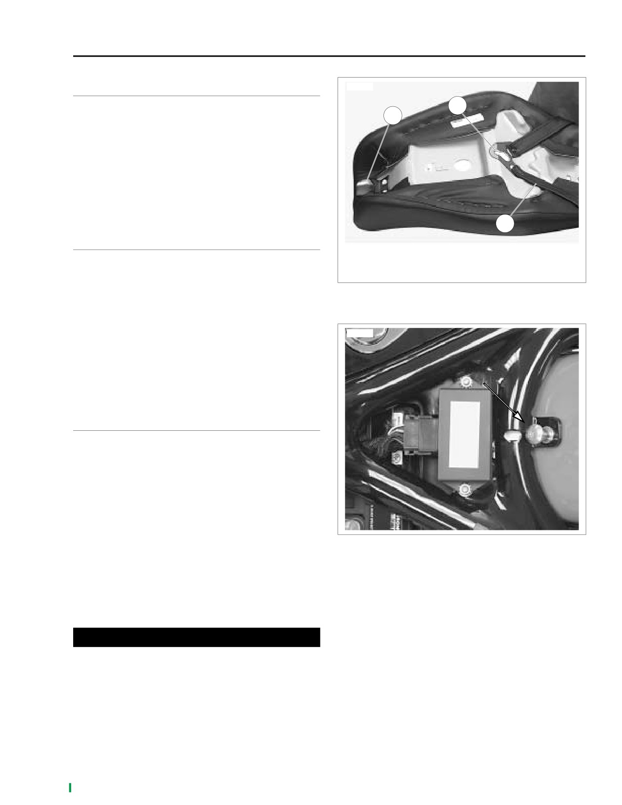
The seat is attached to the vehicle at three points.
2
1
1.
See Figure 2-163. The tongue (1) fits under the rear fuel
tank bracket.
2.
The keyhole (2) locks into the seat post (see Figure 2-
164.).
3.
See Figure 2-165. The mounting bracket (2) bolts to the
seat with two screws (5) and lock washers (6), and
attaches to a seat nut (4) in the rear fender with a screw
(1).
3
REMOVAL
1.
Tongue
1.
See Figure 2-165. Remove screw (1) to detach seat from
2.
Keyhole bracket
rear fender.
3.
Passenger strap
2.
Slide seat forward and lift up slightly to detach keyhole
Figure 2-163. Seat
bracket from seat post. Then slide seat rearward to
detach seat tongue from rear fuel tank bracket.
3.
If dual seat (7, 8, 10), inspect passenger strap (12) for
10057
damage or excessive wear.
NOTE
The passenger strap is not sold separately. If it is damaged,
excessively worn or otherwise unusable, the entire seat
assembly must be replaced.
INSTALLATION
1.
See Figure 2-163. Verify that tongue (1) and keyhole
bracket (2) are tightly secured to seat bottom and that no
rivets are loose or missing. Position seat on frame with
mounting bracket (item 2, Figure 2-165.) at rear.
2.
See Figure 2-163. Slide seat forward until the tongue fits
snugly under rear fuel tank bracket.
3.
Push seat forward, engage keyhole onto seat post (see
Figure 2-164.), then pull seat back slightly.
Figure 2-164. Seat Post
4.
See Figure 2-165. Install seat mounting screw with cap-
tive washer (1) to fasten seat mounting bracket (2) to top
of rear fender. Mounting bracket of solo seat uses for-
ward hole in rear fender; dual seat uses rearward hole.
5.
Pull up on seat to verify that it is locked in place.
6.
Tighten seat mounting screw.
1WARNING
After installing seat, pull upward on front of seat to be
sure it is in locked position. While riding, a loose seat can
shift causing loss of control, which could result in death
or serious injury. (00070a)
7.
Pull up on seat again to verify that it is properly secured
at all three points.
2006 Sportster: Chassis
2-115
HOME
x0076d2x
13
11
7
13
13
12
8
13
10
9
1
2
3
6
4
5
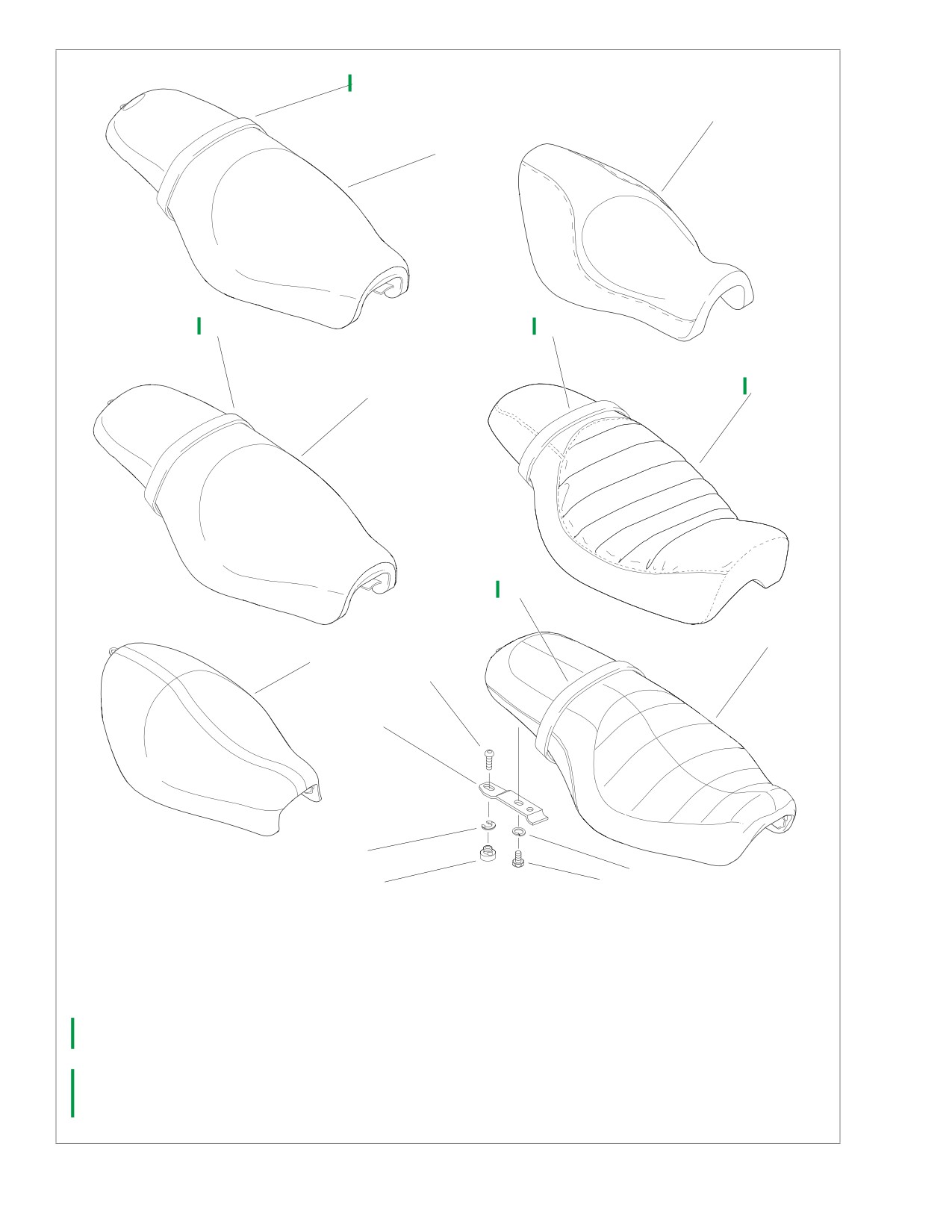
1.
Seat mounting screw with captive washer
NOTE
2.
Mounting bracket
Seat nut (4) is inserted from under side of fender
3.
Retaining clip
and retaining clip (3) is located on top side.
4.
Seat nut
5.
Screw (2)
6.
Lockwasher
7.
Seat assembly, XL 1200C
8.
Seat assembly, XL 883C
9.
Seat assembly, XL 883
10. Seat assembly, XL 1200R
11. Seat assembly, XL 883L
12. Seat assembly, XL 883R
13. Passenger strap (not sold separately)
Figure 2-165. Seat Assembly
2-116
2006 Sportster: Chassis
HOME
RIDER FOOT CONTROLS: XL 883, XL 883L, XL 883R,
XL 1200R
2.33
RIGHT FOOTREST AND REAR
LEFT FOOTREST AND
BRAKE PEDAL ASSEMBLY
SHIFT LEVER ASSEMBLY
Removal
Removal
1.
See Figure 2-166. Remove retaining ring (3), clevis pin
1. See Figure 2-166. Remove retaining ring (15), clevis pin
(5), footrest (1) and spring washer (2). Discard retaining
(17), footrest (18) and spring washer (16). Discard retain-
ring.
ing ring.
2.
Unscrew brake rod (7) from brake pedal (8) and master
2. Remove two screws (14) and left rider footrest support
cylinder bell crank (19).
bracket (13) from frame (12).
3.
Remove retaining ring (26), screw (11) and clevis (4).
3. Remove pinch screw (22) and washer (23). Remove shift
Slide brake pedal (8) off clevis. Discard retaining ring.
lever assembly (24) and rubber washer (21).
4.
Remove two screws (9) and right rider footrest/brake
Installation
pedal support bracket (10) from frame (12).
1. See Figure 2-166. Install rubber washer (21) and shift
Installation
lever (24) on transmission shift lever shaft. Secure with
washer (23) and pinch screw (22). Tighten to 16-20 ft-lbs
1.
See Figure 2-166. Mount right rider footrest/brake pedal
(21.7-27.1 Nm).
support bracket (10) to frame (12) with two screws (9).
Tighten to 45-50 ft-lbs (61.1-67.9 Nm).
2. Attach footrest support bracket (13) to frame (12) with
two screws (14). Tighten to 45-50 ft-lbs (61.1-67.9 Nm).
2.
Slide brake pedal (8) onto clevis (4). Mount clevis on
right rider footrest/brake pedal support bracket. Line up
3. Install footrest
(18) on footrest support bracket with
hole in clevis with hole in support bracket. Secure with
spring washer (16). Make sure spring washer is posi-
screw (11). Tighten to 96-156 in-lbs (10.9-17.6 Nm).
tioned inside support bracket mounting boss with the
Install new retaining ring (26) on end of clevis.
square edge toward the inside. Align holes and push cle-
vis pin
(17) from top down through hole in support
3.
Install footrest (1) on clevis with spring washer (2). Make
bracket. Secure with new retaining ring (15).
sure spring washer is positioned inside clevis with the
square edge toward the inside. Align holes and push cle-
vis pin (5) from top down through hole in clevis. Secure
with new retaining ring (3).
4.
Apply two drops of LOCTITE THREADLOCKER 243
(blue) to threads of both brake rod ball stud screws.
5.
Thread one end of brake rod (7) into master cylinder bell
crank (19). Tighten to 120-180 in-lbs (13.6-20.4 Nm).
6.
Thread other end of brake rod into brake pedal. Tighten
to 96-144 in-lbs (10.9-16.3 Nm).
2006 Sportster: Chassis
2-117
HOME
x0584x2x
24
22
16
23
25
21
18
15
20
14
17
19
13
7
4
3
26
11
1
12
9
10
8
6
2
5
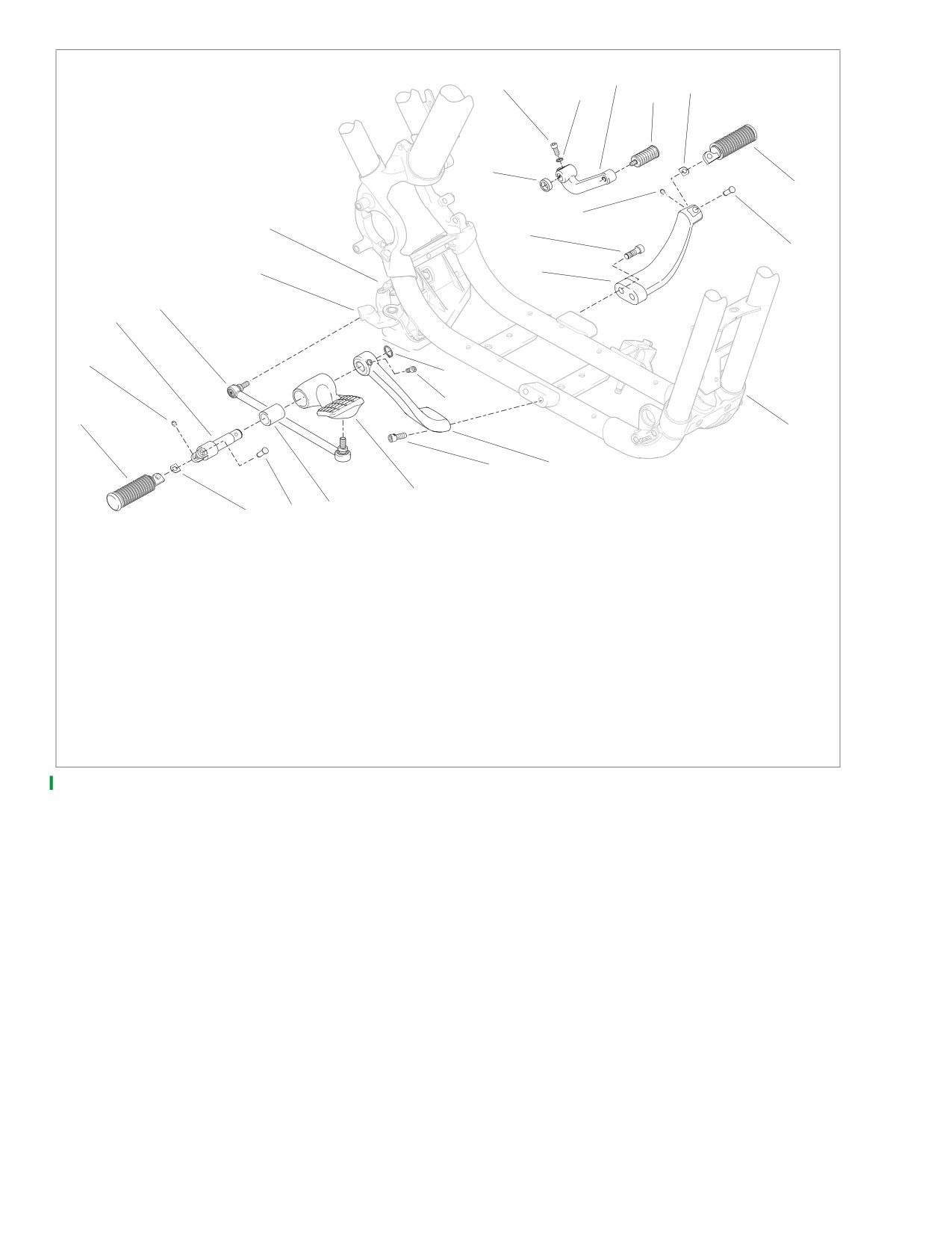
1.
Footrest
14.
Screw (2)
2.
Spring washer
15.
Retaining ring
3.
Retaining ring
16.
Spring washer
4.
Rider footrest clevis
17.
Clevis pin
5.
Clevis pin
18.
Footrest
6.
Bushing
19.
Bell crank
7.
Rear brake rod assembly
20.
Rear brake master cylinder and bracket assembly
8.
Rear brake pedal
21.
Rubber washer
9.
Screw (2)
22.
Pinch screw
10.
Right rider footrest/brake pedal support bracket
23.
Washer
11.
Screw
24.
Shift lever
12.
Frame
25.
Shifter peg
13.
Left rider footrest support bracket
26.
Retaining ring
Figure 2-166. XL 883/XL 883L/XL 883R/XL 1200R Rider Footrests/Foot Controls
2-118
2006 Sportster: Chassis
HOME
RIDER FOOT CONTROLS: XL 883C, XL 1200C
2.34
RIGHT FOOTREST AND REAR
Installation
BRAKE PEDAL ASSEMBLY
1. See Figure 2-167. Position j-clip (12) against frame as
shown. Mount footrest/brake pedal support bracket (10)
and j-clip to frame (13) with screws (9). Tighten to 45-50
Removal
ft-lbs (61.1-67.9 Nm).
NOTE
2. Slide brake pedal (7) onto clevis (4). Mount clevis on
Right side access is improved by exhaust system removal.
footrest/brake pedal support bracket. Line up hole in cle-
See 2.27 EXHAUST SYSTEM.
vis with hole in support bracket. Secure with screw (11).
1.
See Figure 2-167. Remove retaining ring (2), clevis pin
Tighten to 96-156 in-lbs (10.9-17.6 Nm). Install new
(5), footrest (1) and spring washer (3). Discard retaining
retaining ring (16) on end of clevis.
ring.
3. Install footrest (1) on clevis with spring washer (3). Make
2.
Unscrew brake rod (8) from brake pedal (7) and master
sure spring washer is positioned inside clevis with the
cylinder bell crank (14).
square edge toward the inside. Align holes and push cle-
3.
Remove retaining ring (16), screw (11) and clevis (4).
vis pin (5) from top down through hole in clevis. Secure
Slide brake pedal off clevis. Discard retaining ring.
with new retaining ring (2).
4.
Remove two screws (9), footrest/brake pedal support
4. Apply two drops of LOCTITE THREADLOCKER 243
bracket (10) and j-clip (12) from frame (13).
(blue) to threads of both brake rod ball stud screws.
5. Thread one end of brake rod (8) into master cylinder bell
crank (14). Tighten to 120-180 in-lbs (13.6-20.4 Nm).
6. Thread other end of brake rod into brake pedal. Tighten
to 96-144 in-lbs (10.9-16.3 Nm).
2006 Sportster: Chassis
2-119
HOME
x0184a2x
13
15
14
8
7
16
11
6
4
2
1
12
10
9
5
3
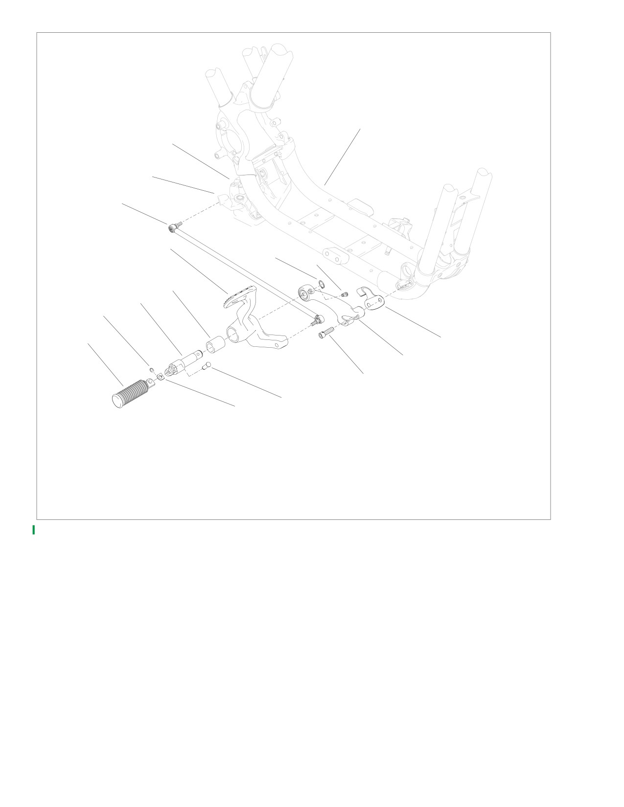
1.
Footrest
9.
Screw (2)
2.
Retaining ring
10. Footrest/brake pedal support bracket
3.
Spring washer
11. Screw
4.
Clevis
12. J-clip
5.
Clevis pin
13. Frame
6.
Bushing
14. Bell crank
7.
Brake pedal
15. Rear brake master cylinder and bracket assembly
8.
Brake rod assembly
16. Retaining ring
Figure 2-167. XL 883C/XL 1200C Forward Controls-Brake Side
2-120
2006 Sportster: Chassis
HOME
LEFT FOOTREST AND
Installation
SHIFT LEVER ASSEMBLY
1.
See Figure 2-168. Install rubber washer (19) and shift
lever (3) onto transmission shifter shaft, with shift lever
arm pointing straight down. Secure with pinch screw (1)
Removal
and washer (2). Tighten pinch screw to
16-20 ft-lbs
(21.7-27.1 Nm).
1.
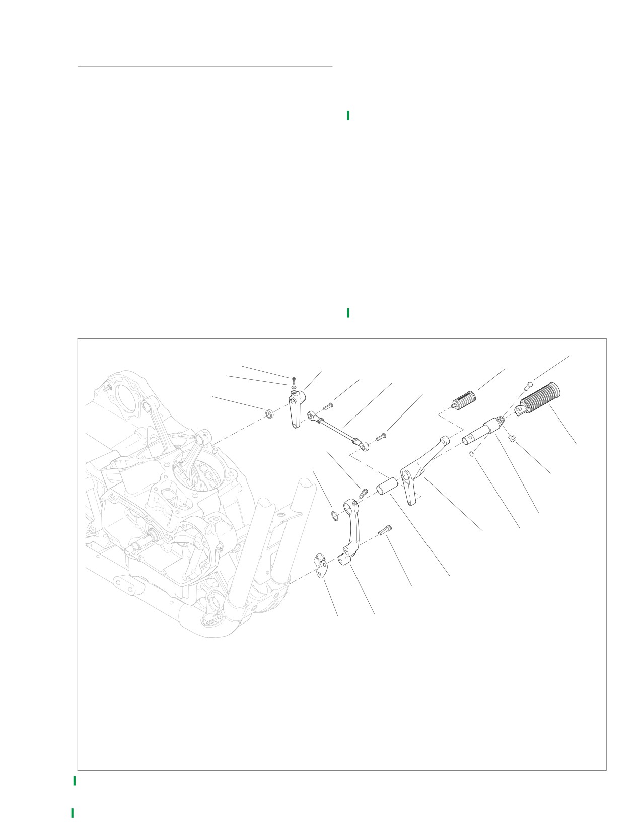
See Figure 2-168. Remove retaining ring (13), clevis pin
2.
Mount j-clip (7) and footrest/shift lever support bracket
(17), footrest (16) and spring washer (15). Discard retain-
(8) to frame with two screws (9). Tighten to 45-50 ft-lbs
ing ring.
(61.1-67.9 Nm).
2.
Unscrew shifter rod assembly
(4) from shifter lever
3.
Slide shifter lever assembly (12) onto clevis (14). Mount
assembly (12) and shift lever (3).
clevis on footrest/shifter lever support bracket. Line up
3.
Remove retaining ring (20), screw (10) and clevis (14).
hole in clevis with hole in support bracket. Secure with
Slide shifter lever assembly off clevis. Discard retaining
screw (10). Tighten to 18-22 ft-lbs (24.4-29.9 Nm). Install
ring.
retaining ring (20) on end of clevis.
4.
Remove two screws (9), footrest/shifter lever support
4.
Mount footrest (16) on clevis with spring washer (15).
bracket (8) and j-clip (7) from frame.
Make sure spring washer is positioned inside clevis with
5.
Remove pinch screw (1), washer (2), shift lever (3) and
the square edge toward the inside. Align holes and push
rubber washer (19) from transmission shift shaft.
clevis pin
(17) from top down through hole in clevis.
Secure with new retaining ring (13).
5.
Thread screw (5) in one end of shifter rod assembly (4)
into shift lever (3). Tighten to 120-180 in-lbs (13.6-20.4
Nm).
6.
Thread screw (6) in other end of shifter rod into shift lever
assembly. Tighten to 120-180 in-lbs (13.6-20.4 Nm).
x0185c2x
17
1
3
18
2
5
4
6
19
10
16
20
15
14
12
13
11
9
7
8
1.
Pinch screw
11. Bushing
2.
Washer
12. Shifter lever assembly
3.
Shift lever
13. Retaining ring
4.
Shifter rod assembly
14. Clevis
5.
Screw
15. Spring washer
6.
Screw
16. Footrest
7.
J-clip
17. Clevis pin
8.
Footrest/shifter lever support bracket
18. Shifter pedal peg
9.
Screw (2)
19. Rubber washer
10. Screw
20. Retaining ring
Figure 2-168. XL 883C/XL 1200C Forward Controls-Shifter Side
2006 Sportster: Chassis
2-121
HOME
ADJUSTING SHIFT PEDAL
10505
5
The foot shift linkage is set at the factory and normally should
need no adjustment. However, if gears do not engage fully or
toe shifter travel is incorrect, adjust linkage rod as follows.
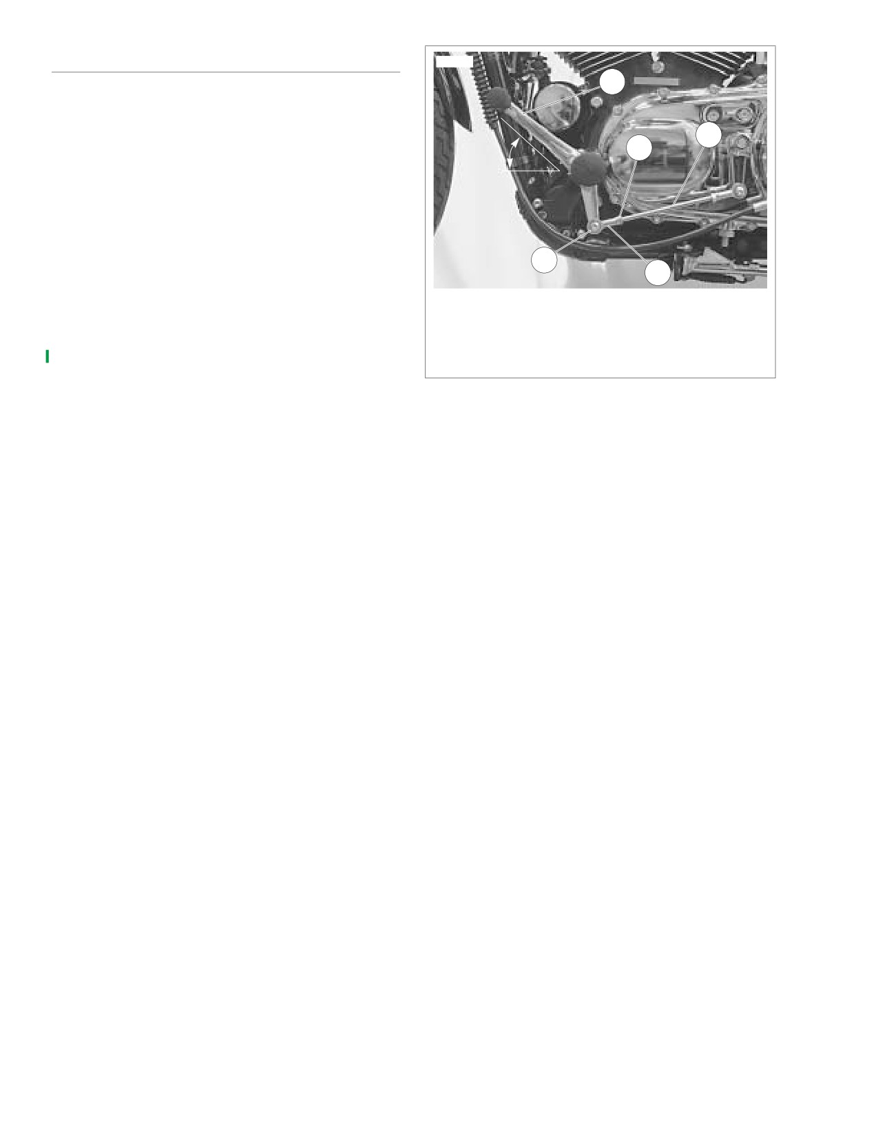
4
3
See Figure 2-169. Adjust shifter rod assembly (4) length until
45°
shifter lever assembly (5) is at 45° as shown in the figure.
1.
Loosen locknuts (3) on both ends of shifter rod.
2.
Remove screw (1) securing ball joint (2) to shifter lever
assembly.
1
2
3.
Turn ball joint or shifter rod to adjust rod length. Tempo-
rarily attach ball joint to shifter lever assembly and check
1.
Screw (2)
angle. Make sure an equal number of threads are visible
2.
Ball joint (2)
on both ends of shifter rod.
3.
Locknut (2)
4.
Shifter rod assembly
4.
When angle of shift lever assembly is at 45°, Install
5.
Shifter lever assembly
screw (1). Tighten to 120-180 in-lbs (13.6-20.4 Nm).
Figure 2-169. XL 883C/XL 1200C: Adjusting Shift Pedal
5.
Holding shifter rod so that it does not turn, tighten lock-
nuts on both ends.
2-122
2006 Sportster: Chassis
HOME
PASSENGER FOOTRESTS
2.35
GENERAL
x0585x2x
3
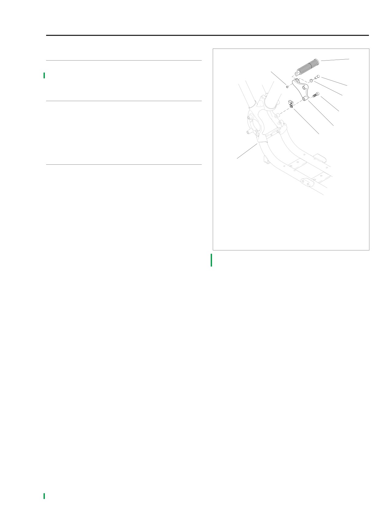
Passenger footrest assemblies are standard equipment on
1
XL 883C, XL 1200C, XL 883R and XL 1200R models only.
2
REMOVAL
4
1.
See Figure 2-170. Remove retaining ring (1), clevis pin
(2), footrest (3) and spring washer (4). Discard retaining
5
ring.
2.
Remove two screws (5) and footrest support bracket (6)
6
from frame (7).
8
INSTALLATION
7
NOTE
See Figure 2-170. On left side of vehicle, a B-clip (8) is posi-
tioned between footrest support bracket (6) and lower support
1.
Retaining ring
bracket hole on frame (7). Make sure this clip is positioned
2.
Clevis pin
between footrest support bracket and frame when attaching
3.
Footrest
support bracket in the next step.
4.
Spring washer
1.
See Figure 2-170. Attach footrest support bracket (6) to
5.
Screw (2)
frame (7) with two screws (5). Tighten to 45-50 ft-lbs
6.
Footrest support bracket
(61.1-67.9 Nm).
7.
Frame
8.
B-clip (left side only)
2.
Install footrest (3) on footrest support bracket with spring
washer (4). Make sure spring washer is positioned inside
Figure 2-170. Passenger Footrest Assembly
support bracket mounting boss with the square edge
(Not Standard Equipment on XL 883 and XL 883L)
toward the inside. Align holes and push clevis pin (2)
from top down through hole in support bracket. Secure
with new retaining ring (1).
2006 Sportster: Chassis
2-123
HOME
FORK LOCK
2.36
REMOVAL
10573
1WARNING
To prevent accidental vehicle start-up, which could
cause death or serious injury, remove maxi-fuse before
proceeding. (00251a)
1.
Open left side cover and remove Maxi-Fuse. Close left
side cover. See 7.25 MAXI-FUSE.
2.
Prepare vehicle for fork lock replacement.
● All models: remove fuel tank. See 4.8 FUEL TANK.
Turn front forks fully to the left.
● XL 883C and XL 1200C models: remove handlebar
upper clamp/speedometer housing. See 2.25 HAN-
DLEBARS. Secure handlebar assembly out of the
way.
3.
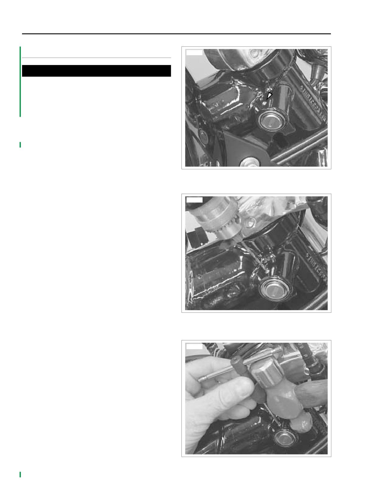
See Figure 2-171. See Figure 2-172. Using a 5/64 inch
Figure 2-171. Fork Lock Pin
(2 mm) drill bit, carefully drill a hole in the center of the
lock pin.
NOTE
10574
Take time to carefully orient drill bit to center of lock pin. If drill
bit “walks” off-center, removal of lock pin will be difficult.
4.
See Figure 2-173. To remove lock pin, insert a screw
extractor into the 5/64 in. (2 mm) hole. Hold body of
screw extractor with a pliers or tap handle and using a
small hammer gently “tap” on the pliers or tap handle to
remove lock pin.
5.
Remove lock assembly.
Figure 2-172. Drilling Lock Pin
10575
Figure 2-173. Removing Lock Pin
2-124
2006 Sportster: Chassis
HOME
5. Verify proper operation of fork lock.
INSTALLATION
a. Turn front forks fully to the left.
1.
Insert new lock assembly in frame lock housing.
b. Insert key into fork lock. Turn key 90 degrees clock-
wise.
2.
Align lock pin hole in new lock assembly with hole in the
frame lock housing.
c. Verify that front forks are locked and cannot be
turned.
3.
Drive new lock pin in position (flush with frame lock
housing).
d. Turn key 90 degrees counterclockwise and remove
from fork lock.
4.
Reassemble motorcycle.
e. Verify that front forks are now free to fully turn right
● XL 883C and XL 1200C models: Install handlebar
and left.
assembly and upper clamp/speedometer housing.
6. Open left side cover and install Maxi-Fuse. Close left
See 2.25 HANDLEBARS.
side cover. See 7.25 MAXI-FUSE.
● All models: install fuel tank. See 4.8 FUEL TANK.
2006 Sportster: Chassis
2-125
HOME
NOTES
2-126
2006 Sportster: Chassis
HOME
SPECIFICATIONS
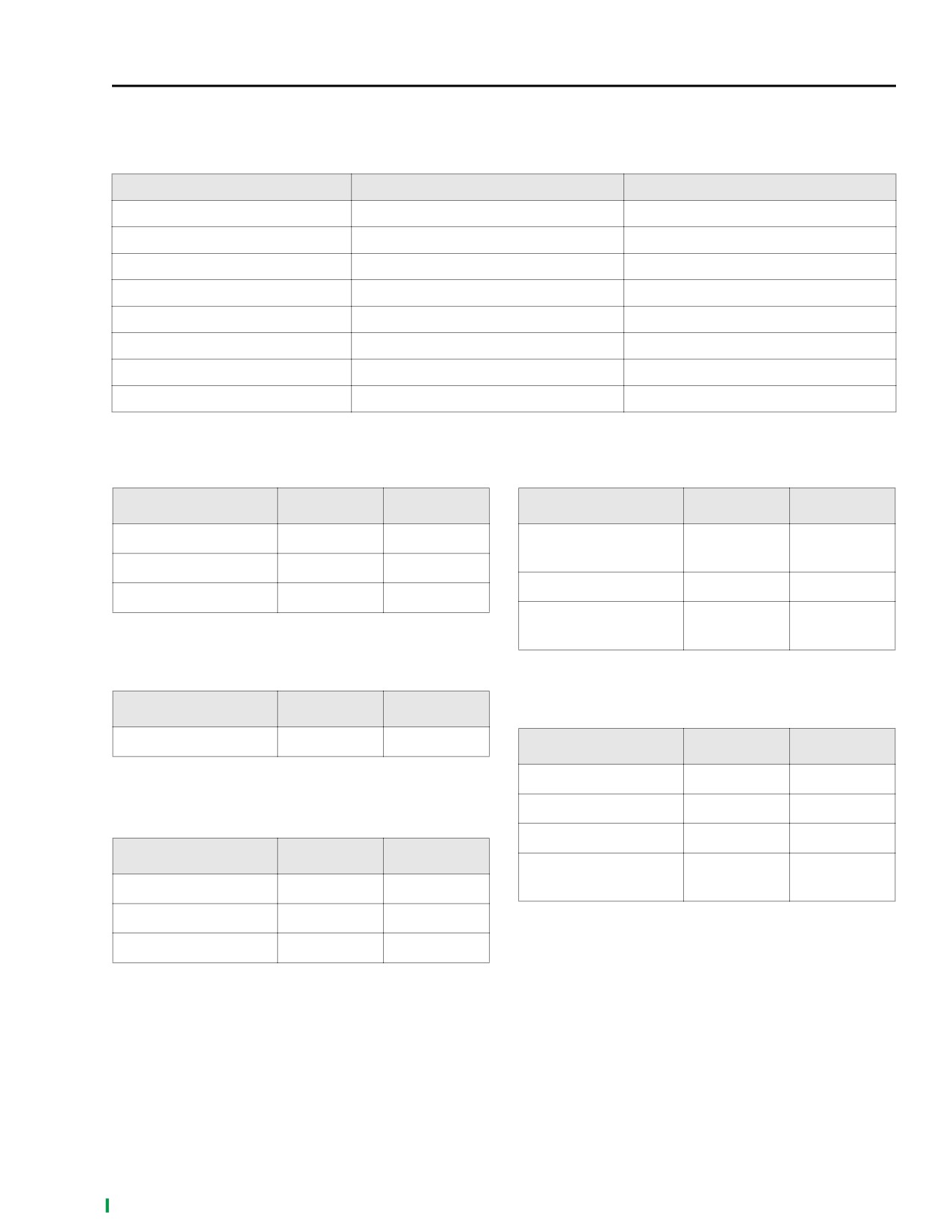
3.1
Table 3-1. General Specifications
GENERAL
883 CC
1200 CC
Number of Cylinders
2
2
Type
4-cycle, 45° V
4-cycle, 45° V
Bore
3.0005 in. (76.20 mm)
3.498 in. (88.85 mm)
Stroke
3.812 in. (96.82 mm)
3.812 in. (96.82 mm)
Piston Displacement
53.86 cu. in. (883 cc)
73.2 cu. in. (1203 cc)
Torque
51.0 ft-lbs (69.2 Nm) @ 4300 RPM
79.0 ft-lbs (107.2 Nm) @ 3500 RPM
Compression Ratio
8.9:1
9.7:1
Oil tank capacity with filter
3.6 qt. (3.4 Liters)
3.6 qt. (3.4 Liters)
Table 3-2. Rocker Arms-883/1200 cc
Table 3-5. Cylinder Heads-883/1200 cc
ITEM
INCHES
MM
ITEM
INCHES
MM
Shaft in bushing (loose)
0.0005-0.0020
0.013-0.051
Valve guide in head
0.0033-0.0020
0.084-0.051
(tight)
End Clearance
0.003-0.013
0.08-0.33
Valve seat in head
0.0035-0.0010
0.089-0.025
Bushing fit in rocker arm
0.004-0.002
0.10-0.05
Head gasket surface
0.006
0.15
(flatness)
Table 3-3. Rocker Arm Shafts-883/1200 cc
ITEM
INCHES
MM
Table 3-6. Valves-883/1200 cc
Shaft fit in rocker cover
0.0007-0.0022
0.018-0.056
ITEM
INCHES
MM
Exhaust fit in guide
0.001-0.003
0.0254-0.0762
Intake fit in guide
0.001-0.003
0.0254-0.0762
Table 3-4. Tappets-883/1200 cc
Seat Width
0.040-0.062
1.02-1.57
ITEM
INCHES
MM
Stem protrusion from
2.028-2.064
51.511-52.426
Fit in guide
0.0008-0.0023
0.020-0.058
cylinder valve pocket
Roller fit
0.0006-0.0013
0.015-0.033
Roller end clearance
0.008-0.022
0.203-0.559
2006 Sportster: Engine
3-1
HOME
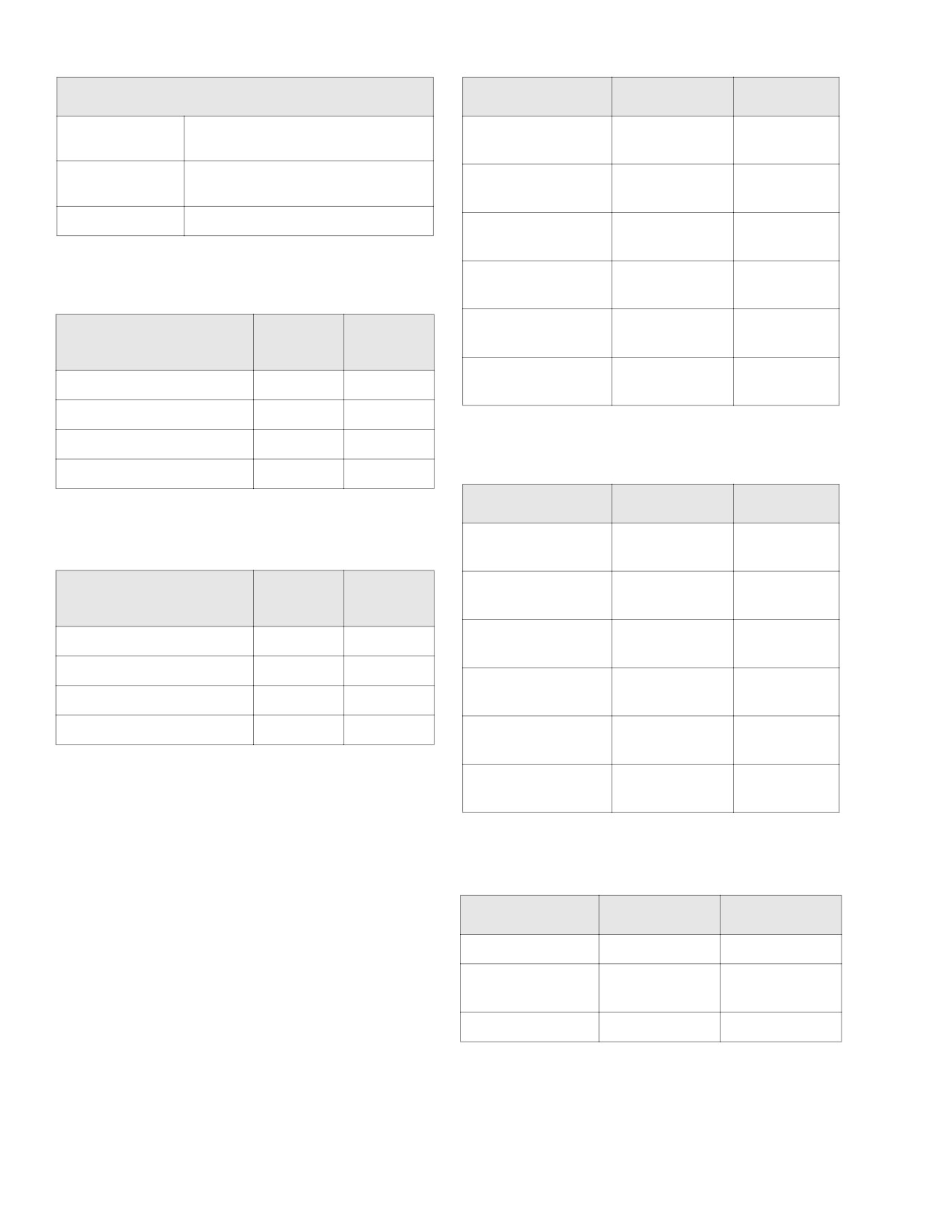
Table 3-7. Valve Springs-883/1200 cc
Table 3-10. Pistons-883 cc
INTAKE/EXHAUST
ITEM
INCHES
MM
Closed
135 lbs @ 1.850 in.
Compression ring
0.010-0.023
0.25-0.58
(61.2 kg @ 47.0 mm)
gap (top and 2nd)
Open
312 lbs @ 1.300 in.
Oil control ring
0.010-0.053
0.25-1.35
(141.5 kg @ 33.0 mm)
rail gap
Free length
2.325 in. (59.1 mm)
Compression ring
0.0020-0.0045
0.051-0.114
side clearance top
Compression ring
0.0020-0.0045
0.051-0.114
Table 3-8. Cylinders-883 cc
side clearance 2nd
Oil control ring
0.0014-0.0074
0.036-0.188
BORE DIAMETER
INCHES
MM
side clearance
+ 0.0002 in. (0.0051 mm)
Piston pin fit (loose;
0.00005-0.00045
0.0013-0.0114
Standard
3.0005
76.213
room temperature)
0.005 in. O.S. (oversize)
3.0048
76.323
0.010 in. O.S.
3.0098
76.449
Table 3-11. Pistons-1200 cc
0.020 in. O.S.
3.0198
76.703
ITEM
INCHES
MM
Compression ring
0.007-0.020
0.18-0.51
Table 3-9. Cylinders-1200 cc
gap (top and 2nd)
Oil control ring
0.009-0.052
0.23-1.32
BORE DIAMETER
INCHES
MM
rail gap
+ 0.0002 in. (0.0051 mm)
Top compression ring
0.0020-0.0045
0.051-0.114
Standard
3.4978
88.844
side clearance
0.005 in. O.S. (oversize)
3.502
88.95
2nd compression ring
0.0016-0.0041
0.041-0.104
0.010 in. O.S.
3.507
89.08
side clearance
0.020 in. O.S.
3.517
89.33
Oil control ring
0.0016-0.0076
0.041-0.193
side clearance
Piston pin fit (loose;
0.00005-0.00045
0.0013-0.0114
room temperature)
Table 3-12. Connecting Rods-883/1200 cc
ITEM
INCHES
MM
Piston pin fit (loose)
0.00125-0.00175
0.0318-0.0445
Side play between
0.005-0.025
0.013-0.64
flywheels
Fit on Crankpin
0.0004-0.0017
0.010-0.043
3-2
2006 Sportster: Engine
HOME
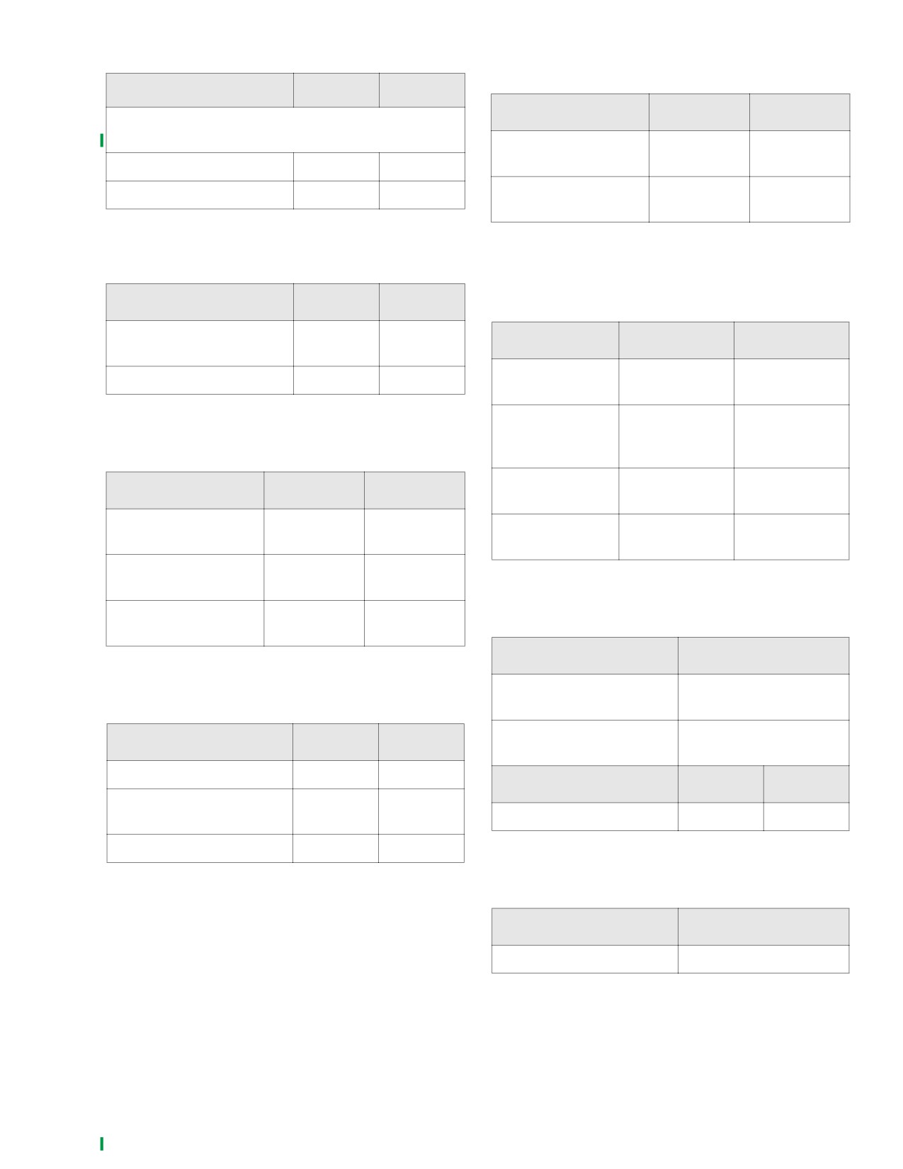
Table 3-13. Oil Pressure-883/1200 cc
Table 3-17. Sprocket Shaft Bearing-
883/1200 cc
ITEM
PSI
KN/CM2
ITEM
INCHES
MM
Oil pressure at normal operating temperature (pressure
reading taken at oil pressure switch fitting)
Outer race fit in
0.006
0.152
crankcase (tight)
interference fit
Engine speed 1000 RPM
7-12
0.5-0.8
Inner race fit on shaft
0.006
0.152
Engine speed 2500 RPM
10-17
0.7-1.2
(tight)
interference fit
Table 3-14. Oil Pump-883/1200 cc
Table 3-18. Pinion Shaft Bearing-
ITEM
INCHES
MM
883/1200 cc
Feed/scavenge inner/outer
0.003
0.08
ITEM
INCHES
MM
gerotor clearance
Pinion shaft
1.2500-1.2496
31.750-31.740
Shaft to pump clearance
0.0025
0.064
journal diameter
Outer race
1.5646-1.5652
39.741-39.756
diameter in right
Table 3-15. Gearcase-883/1200 cc
crankcase
Bearing running
0.00012-0.00088
0.0030-0.0224
ITEM
INCHES
MM
clearance
Cam gear shaft in
0.0007-0.0022
0.018-0.056
Fit in cover
0.0023-0.0043
0.058-0.109
bushing (loose)
bushing (loose)
Cam gear shaft end play
0.005-0.024
0.13-0.61
(min. except rear intake)
Rear intake cam gear
0.006-0.024
0.15-0.61
Table 3-19. Ignition System-883/1200 cc
shaft end play (min.)
ITEM
VALUE
Timing during engine
0° BTDC
Table 3-16. Flywheels-883/1200 cc
cranking
Timing with engine speed at
10° BTDC
ITEM
INCHES
MM
950-1050
Runout (flywheels at rim)
0.000-0.010
0.00-0.25
ITEM
INCHES
MM
Runout (shaft at flywheel
0.000-0.002
0.00-0.05
Spark plug gap (6R12) (in.)
0.038-0.043
0.97-1.09
end)
End play
0.003-0.010
0.076-0.254
Table 3-20. Engine Speed-883/1200 cc
ITEM
VALUE
Slow Idle (RPM)
950-1050
2006 Sportster: Engine
3-3