Harley Davidson 2006 Sportster XLH MODELS. Service Manual - page 8
HOME
NOTES
FRONT WHEEL
● Do not operate the front brake lever with the front wheel
removed or the caliper pistons may be forced out.
Reseating the pistons requires disassembly of the cali-
Removal
per.
1.
Block motorcycle underneath frame so front wheel is
● On models with dual disc brakes, remove both calipers.
raised off the ground.
2.
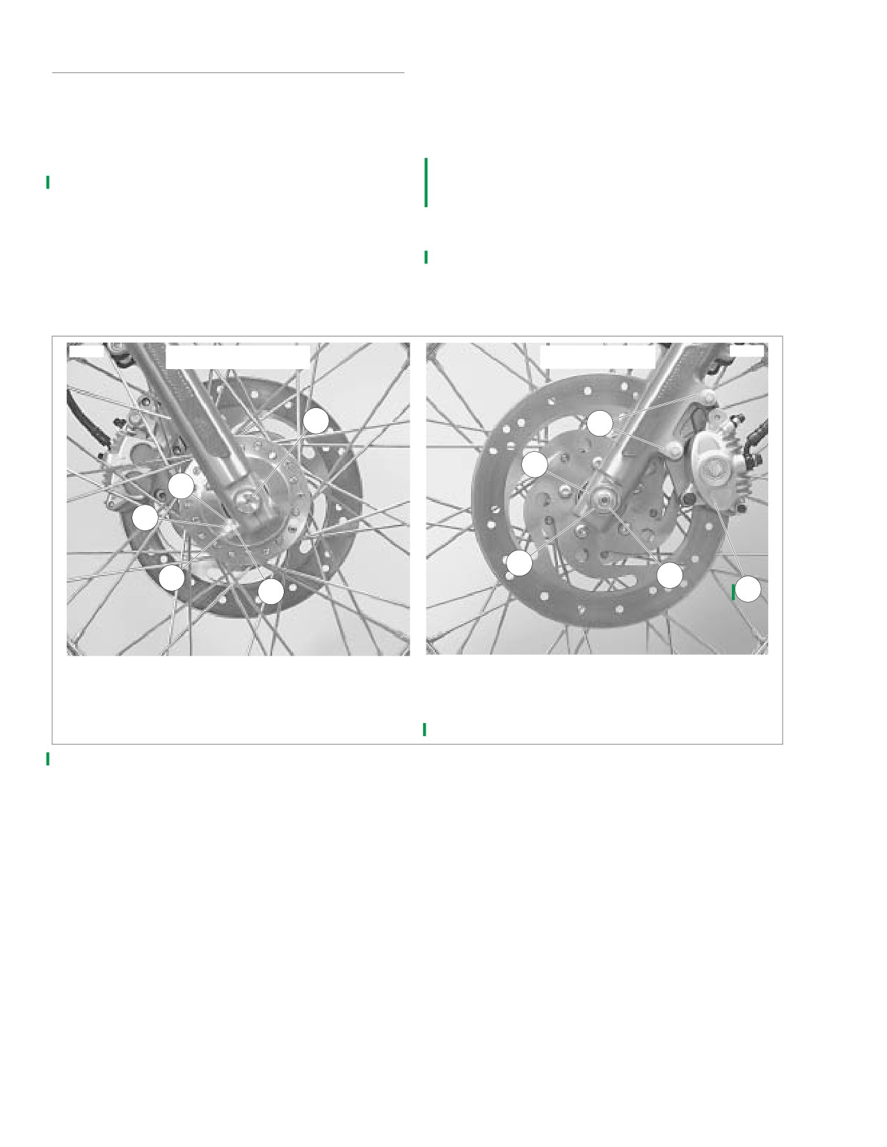
See Figure 2-5. Remove brake caliper mounting screws
3. Remove axle nut (6), lockwasher (7) and flat washer (8)
(9). Slide caliper (10) off brake disc and secure caliper
from axle on left side of vehicle.
out of the way.
4. On right side of vehicle, loosen nut (4) on pinch screw
(1). Pull axle out of hub while supporting wheel.
5. Remove spacer and front wheel assembly.
8957a
8958a
RIGHT SIDE
LEFT SIDE
5
9
8
3
4
7
1
6
2
10
1.
Pinch screw
6.
Axle nut
2.
Washer
7.
Lockwasher
3.
Lockwasher
8.
Flat washer
4.
Nut
9.
Brake caliper mounting screws
5.
Axle
10. Brake caliper
Figure 2-5. Front Wheel Mounting-Typical (Laced Front Wheel Shown)
2-10
2006 Sportster: Chassis
HOME
Disassembly
Assembly
If necessary, remove tire. See 2.10 TIRES.
Cast Front Wheel
Cast Front Wheel
1WARNING
NOTE
Label all components as they are removed so they may be
Be sure that brake fluid or other lubricants do not con-
returned to their original locations.
tact brake pads or discs. Such contact can adversely
affect braking ability, which could cause loss of control,
1.
See Figure 2-6. Remove bearing spacers (10, 12) from
resulting in death or serious injury. (00290a)
right and left sides of wheel.
1. See Figure 2-6. Install hub spacer (11) and wheel bear-
2.
If necessary, remove five screws (1) and left side brake
ings (5) if removed. See SEALED WHEEL BEARINGS,
disc (14).
later in this section for installation procedure.
3.
If necessary, remove five screws and right side brake
2. If necessary, install brake disc(s) as follows:
disc (15) (XL 883R and XL 1200R only) or hub plate (9)
(all models except XL 883R and XL 1200R).
a. Apply two drops of LOCTITE THREADLOCKER 243
(blue) to five screws (1). Install right side brake disc
4.
If necessary, remove roller bearings (5) and hub spacer
(15) (XL 883R and XL 1200R only) or hub plate (9)
(11). See SEALED WHEEL BEARINGS later in this sec-
(all models except XL 883R and XL 1200R). Secure
tion for removal procedure.
with screws and tighten to 16-24 ft-lbs (21.7-32.6
Laced Front Wheel
Nm).
1.
See Figure 2-7. Remove spacers (10, 12) from right and
b. Apply two drops of LOCTITE THREADLOCKER 243
left sides of wheel.
(blue) to five screws (1). Install left side brake disc
2.
If necessary, remove five screws (1) and brake disc (15).
(14). Secure with screws and tighten to 16-24 ft-lbs
(21.7-32.6 Nm).
3.
If necessary, remove wheel bearings (5) and hub spacer
(11). See SEALED WHEEL BEARINGS later in this sec-
3. Install spacers (10, 12) on right and left sides of wheel.
tion for removal procedure.
4. Verify that wheel is true. See
2.9 CHECKING CAST
WHEEL RUNOUT.
NOTE
If only rim is to be replaced, tape spokes together to hold
5. Install tire, if removed. See 2.10 TIRES.
position on hub and remove spokes from rim. Install taped
Laced Front Wheel
hub/spoke assembly to new rim and tighten spokes. Then
1. See Figure 2-7. Install hub spacer (11) and wheel bear-
remove tape and true wheels. See 2.6 WHEEL LACING: 19
ings (5) if removed. See SEALED WHEEL BEARINGS,
INCH RIM or 2.7 WHEEL LACING: 21 INCH RIM. Then, see
later in this section for installation procedure.
2.8 TRUING LACED WHEELS.
2. If hub (13) and rim (6) were disassembled, reassemble
4.
If it is necessary to disassemble wheel, unscrew spoke
and true wheel. See 2.6 WHEEL LACING: 19 INCH RIM
nipples and spokes (8) and slide each spoke out of hub
or 2.7 WHEEL LACING: 21 INCH RIM. Then see 2.8
(13).
TRUING LACED WHEELS.
Cleaning and Inspection
1
WARNING
1.
Inspect all parts for damage or excessive wear.
Be sure that brake fluid or other lubricants do not con-
tact brake pads or discs. Such contact can adversely
1WARNING
affect braking ability, which could cause loss of control,
Always replace brake pads in complete sets for correct
resulting in death or serious injury. (00290a)
and safe brake operation. Improper brake operation
3. If necessary, install brake disc as follows: apply two
could result in death or serious injury. (00111a)
drops of LOCTITE THREADLOCKER 243 (blue) to five
2.
Inspect brake pads and disc(s). See 1.10 BRAKE PADS
screws (1). Install brake disc (15). Secure with screws
AND DISCS. Replace as necessary.
and tighten to 16-24 ft-lbs (21.7-32.6 Nm).
4. Install spacers (10, 12) on right and left sides of wheel.
5. Verify that wheel is true. See
2.8 TRUING LACED
WHEELS.
6. Install tire, if removed. See 2.10 TIRES.
2006 Sportster: Chassis
2-11
HOME
x0359a2x
1
LEFT
SIDE
4
2
12
3
5
14
15
1
11
6
13
5
7
9
8
10
RIGHT
SIDE
1.
Screw (XL 883R/XL 1200R-10, all others-5)
9.
Hub plate (all except XL 883R/XL 1200R)
2.
Washer
10. Bearing spacer, narrow
3.
Lockwasher
11. Hub spacer
4.
Nut
12. Bearing spacer, wide
5.
Roller bearing (2)
13. Front axle
6.
Valve cap
14. Brake disc L.H.
7.
Valve stem assembly with nut
15. Brake disc R.H. (XL 883R/XL 1200R only)
8.
Wheel assembly, 19 in.
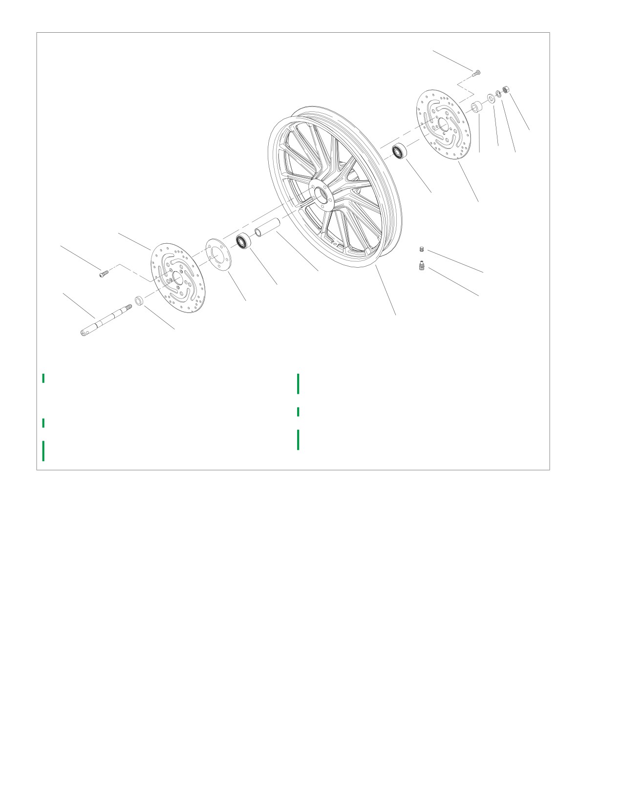
Figure 2-6. Cast Front Wheel
2-12
2006 Sportster: Chassis
HOME
x0439b2x
17
3
4
1
LEFT
SIDE
15
13
2
5
12
19
5
18
11
1
6
RIGHT
SIDE
14
10
7
9
8
16
1.
Screw (XL 883R/XL 1200R-10, all others-5)
11. Hub spacer
2.
Washer
12. Bearing spacer, wide
3.
Lockwasher
13. Wheel hub
4.
Nut
14. Front axle
5.
Roller bearing (2)
15. Brake disc, L.H.
6.
Rim, 19 in. or 21 in., standard
16. Valve stem nut
7.
Valve cap
17. Rim, 21 in., profile
8.
Spoke and nipple
18. Wheel assembly, 21 in., profile rim
9.
Wheel assembly, 19 in. or 21 in., standard rim
19. Brake disc, R.H. (XL 883R/XL 1200R only)
10. Bearing spacer, narrow
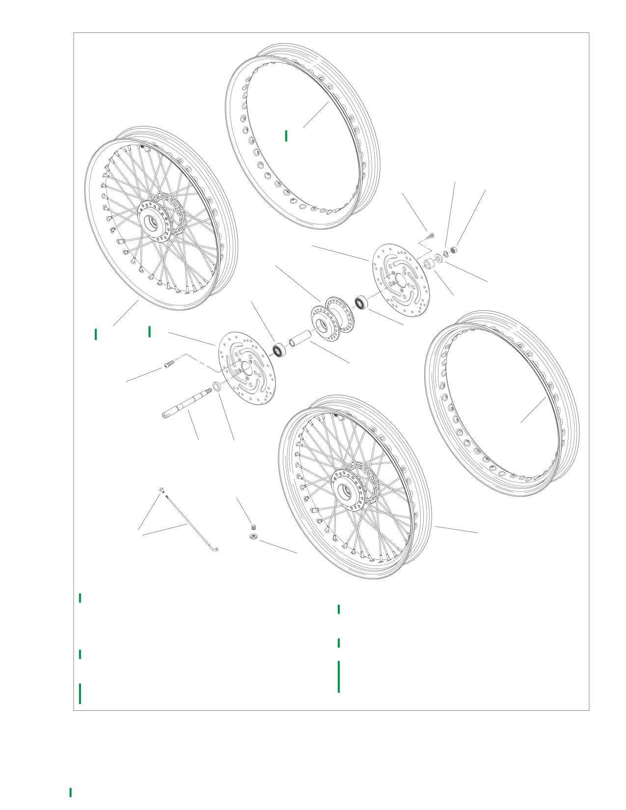
Figure 2-7. Laced Front Wheel
2006 Sportster: Chassis
2-13
HOME
Installation
1
WARNING
1.
Apply a light coat of ANTI-SEIZE LUBRICANT to axle.
Check wheel bearing end play after tightening axle nut to
2.
Position wheel between forks. Verify that spacers on right
specified torque. Excessive end play can adversely affect
and left side of wheel bearings are in position.
stability and handling. Insufficient end play can cause
3.
See Figure
2-5. With pinch screw
(1) loose, insert
bearing seizure. Either condition can cause loss of con-
threaded end of axle (5) through right side fork. Push
trol, which could result in death or serious injury.
axle through fork and wheel hub until it begins to emerge
(00285a)
from left side of hub.
8.
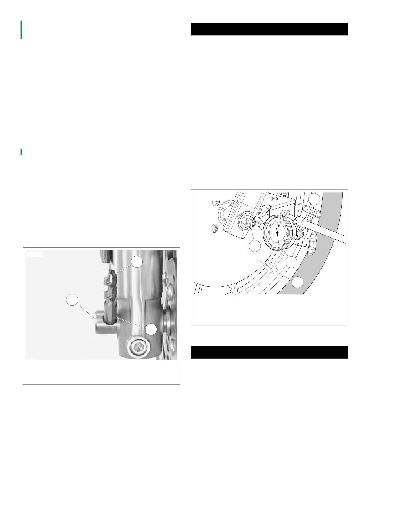
See Figure 2-9. Check wheel bearing end play.
4.
Push axle through left fork, until axle shoulder contacts
external wheel spacer on right fork side.
a. Mount a magnetic base dial indicator on the brake
disc. Set the indicator contact point on the end of the
5.
Install flat washer (8), lockwasher (7) and axle nut (6)
axle.
over threaded end of axle. Insert screwdriver or steel rod
through hole in axle on right side of vehicle. While hold-
b. Move the wheel back as far as it will go. Holding the
ing axle stationary, tighten axle nut to 50-55 ft-lbs (67.9-
wheel in position, zero the dial indicator gauge.
74.6 Nm).
c. Move the wheel forward as far as it will go. Note the
6.
See Figure 2-8. If servicing a vehicle with dual front
reading of the dial indicator. The lateral movement or
brakes, align calipers to brake discs as follows:
end play must be less than 0.002 in. (0.05 mm).
Repeat the procedure to verify the reading.
a. Make sure axle pinch screw nut is loose.
d. If the end play is
0.002 in. (0.05 mm) or more,
b. Insert 7/16 in. drill bit (2) into hole in axle (1) as far
replace the wheel bearings.
as it will go.
c. Position fork leg against edge of drill bit. Contact
point (3) must the have edge of drill bit touching the
x0121a2x
edge of fork leg.
1
d. Tighten axle pinch screw to
21-27 ft-lbs
(28.5-36.6 Nm) and withdraw drill bit.
7.
Install brake caliper(s). See INSTALLATION under 2.14
FRONT BRAKE CALIPER.
3
10351
2
4
2
1.
Magnetic base
1
2.
Brake disc
3.
Axle
4.
Dial indicator
3
Figure 2-9. Check Wheel Bearing End Play
1WARNING
1. Axle
Whenever a wheel is installed and before moving the
2. Drill bit
motorcycle, pump brakes to build brake system pres-
3. Contact point
sure. Insufficient pressure can adversely affect brake
performance, which could result in death or serious
Figure 2-8. Dual Brake Disc Alignment
injury. (00284a)
9. Pump brake lever to move pistons out until they contact
outside brake pad(s). Verify piston location against pad.
2-14
2006 Sportster: Chassis
HOME
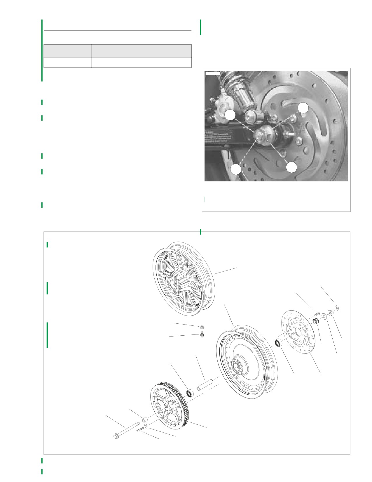
7. Remove rear wheel assembly.
REAR WHEEL
NOTE
Do not operate rear brake pedal with rear wheel removed or
caliper piston may be forced out of piston bore. Reseating
PART NO.
SPECIALTY TOOL
piston requires disassembly of caliper.
HD-45968
Fat Jack
10625
Removal
1.
Secure motorcycle upright on a suitable lift. Raise rear
end of motorcycle high enough to permit wheel removal,
using a FAT JACK (or similar lifting device) underneath
frame.
3
2
2.
Remove rear muffler. See 2.27 EXHAUST SYSTEM.
3.
Remove right lower shock absorber nut and pull screw
out slightly. This will help avoid damage to sprocket when
rear wheel is removed.
4.
See Figure 2-10. Remove e-clip (2), axle nut (1) and
spacer (3).
5.
Gently tap end of axle (4) with a soft hammer to loosen.
1
Pull axle free of rear fork assembly.
4
6.
Slide wheel forward and slip belt off sprocket.
1.
Axle nut
NOTES
2.
E-clip
● Tension may have to be relieved before belt will slip off.
3.
Spacer
This may cause wheel spacers to fall out.
4.
Rear axle
● It is not necessary to disassemble or remove rear brake
Figure 2-10. Rear Wheel Mounting
caliper in order to remove rear wheel.
1.
E-clip
x0569b2x
2.
Screw (5)
3.
Spacer
4.
Washer (5)
5.
Axle nut
17
LEFT
6.
Roller bearing (2)
SIDE
7.
Sprocket
8.
Spacer, wide
1
9.
Spacer, narrow
15
10. Brake disc
16
11. Valve cap
12. Axle
13. Valve stem
11
14. Hub spacer
15. Screw (5)
16. Wheel assembly, disc
13
17. Wheel assembly, cast
5
9
14
6
3
6
10
8
12
7
RIGHT
4
SIDE
2
Figure 2-11. Cast or Disc Rear Wheel
2006 Sportster: Chassis
2-15
HOME
Disassembly
Assembly
If necessary, remove tire. See 2.10 TIRES.
Laced Rear Wheel
NOTE
If wheel was disassembled, reassemble hub, rim, spokes and
● Sportster models sold in the Japanese market are
nipples, and tighten spokes. See 2.5 WHEEL LACING: 16
equipped with rear wheel compensating sprockets. See
INCH RIM.
Appendix D for the correct disassembly and repair proce-
Cast, Disc or Laced Rear Wheel
dures.
Cast or disc wheel: see Figure 2-11. Laced wheel: see Figure
● Label all components as they are removed so they may
2-12.
be returned to their original locations.
1. Install bearing spacer (14) and wheel bearings (6), if
Cast, Disc or Laced Rear Wheel
removed. See SEALED WHEEL BEARINGS, which fol-
Cast or Disc wheel: see Figure 2-11. Laced wheel: see Fig-
lows, for installation procedure.
ure 2-12.
2. If brake disc (10) was removed, install brake disc on
1.
Remove spacers (8, 9) from left and right sides of wheel.
valve stem side of wheel.
2.
If necessary, remove five screws (15) to detach rear
a. Apply a drop of LOCTITE THREADLOCKER 243
brake disc (10) from left side of wheel.
(blue) to each of the five screws (15).
3.
If necessary, remove five screws (2) and washers (4) to
b. Install disc. Secure with screws and tighten to 30-45
detach rear sprocket (7) from right side of wheel.
ft-lbs (40.7-61.1 Nm).
4.
If necessary, remove wheel bearings (6) and bearing
NOTE
spacer (14). See SEALED WHEEL BEARINGS, which
Sportster models sold in the Japanese market are equipped
follows, for removal procedure.
with rear wheel compensating sprockets. See Appendix D for
Laced Rear Wheel
the correct assembly/installation procedure.
NOTE
3. If rear sprocket (7) was removed, install sprocket on side
If only rim is to be replaced, tape spokes together to hold
of wheel opposite valve stem.
position on hub and remove spokes from rim. Install taped
a. Apply two drops of LOCTITE THREADLOCKER 262
hub/spoke assembly to new rim and tighten spokes. See 2.5
(red) to each of the five screws (2). Install sprocket
WHEEL LACING: 16 INCH RIM. Then true wheel. See 2.8
using screws and washers (4).
TRUING LACED WHEELS.
b. Tighten screws to 55-65 ft-lbs (74.6-88.2 Nm).
See Figure 2-12. If it is necessary to disassemble wheel,
4. Verify that wheel assembly is true. See 2.8 TRUING
unscrew spoke nipples and spokes (19) and slide each spoke
LACED WHEELS or 2.9 CHECKING CAST WHEEL
out of hub (18).
RUNOUT.
5. Install tire, if removed. See 2.10 TIRES.
Cleaning and Inspection
1.
Inspect all parts for damage or excessive wear.
1WARNING
Always replace brake pads in complete sets for correct
and safe brake operation. Improper brake operation
could result in death or serious injury. (00111a)
2.
Inspect brake pads and disc. See 1.10 BRAKE PADS
AND DISCS.
3.
Inspect rear belt and sprocket. See 1.16 REAR BELT
AND SPROCKETS.
2-16
2006 Sportster: Chassis
HOME
x0363c2x
20
21
1
LEFT
SIDE
15
6
18
5
14
9
3
6
10
8
12
7
4
2
RIGHT
SIDE
11
19
16
17
13
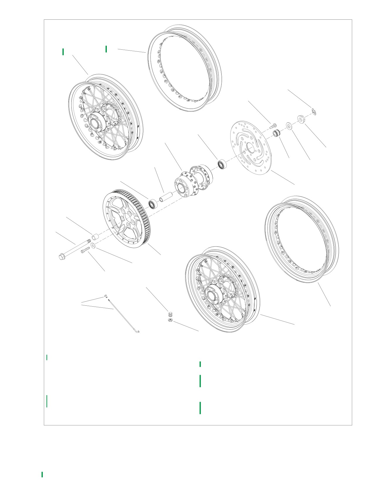
1.
E-clip
12. Axle
2.
Screw (5)
13. Valve stem nut
3.
Spacer
14. Hub spacer
4.
Washer (5)
15. Brake disc screw (5)
5.
Axle nut
16. Rim, standard (all except XL 883C/XL 1200C)
6.
Roller bearing (2)
17. Wheel assembly, 16 in., standard rim
7.
Sprocket
18. Hub
8.
Spacer, wide
19. Spoke and nipple (40)
9.
Spacer, narrow
20. Rim, profile (XL 883C/XL 1200C only)
10. Brake disc
21. Wheel assembly, 16 in., profile rim
11. Valve cap
Figure 2-12. Laced Rear Wheel
2006 Sportster: Chassis
2-17
HOME
8. Tighten axle nut to 72-78 ft-lbs (98-106 Nm). Install e-
Installation
clip.
1.
Place wheel centrally in the rear fork assembly with the
brake disc in the caliper, between the brake pads. Slide
1WARNING
wheel far enough forward to slip belt over sprocket and
then slide the wheel back.
Check wheel bearing end play after tightening axle nut to
2.
See Figure 2-11. See Figure 2-12. Position sprocket side
specified torque. Excessive end play can adversely affect
spacer (8) between wheel and rear fork.
stability and handling. Insufficient end play can cause
bearing seizure. Either condition can cause loss of con-
3.
Apply a light coat of ANTI-SEIZE LUBRICANT to axle
trol, which could result in death or serious injury.
(12).
(00285a)
4.
Insert axle (12) through right side of rear fork and right
side axle adjuster, sprocket side spacer
(8), wheel
9. Check wheel bearing end play.
assembly, disc side spacer (9), rear caliper bracket, and
a. Mount a magnetic base dial indicator on the brake
left side of rear fork and left side axle adjuster.
disc. Set the indicator contact point on the end of the
5.
Install spacer (3) and axle nut (5) on left end of axle. Do
axle.
not tighten nut at this time.
b. Move the wheel back as far as it will go. Holding the
6.
Slide right lower shock absorber screw back in place.
wheel in position, zero the dial indicator gauge.
Install nut and tighten screw to 45-50 ft-lbs (61.1-67.9
c. Move the wheel forward as far as it will go. Note the
Nm).
reading of the dial indicator. The lateral movement or
end play must be less than 0.002 in. (0.05 mm).
NOTE
Repeat the procedure to verify the reading.
If rear brake caliper was disassembled or removed, see 2.15
REAR BRAKE CALIPER for the proper assembly and instal-
d. If end play is 0.002 in. (0.05 mm) or more, remove
lation procedure.
wheel and replace both wheel bearings.
7.
Check for proper belt tension and rear wheel alignment.
See BELT DEFLECTION ADJUSTMENT and WHEEL
1WARNING
ALIGNMENT under 1.15 REAR BELT DEFLECTION.
Whenever a wheel is installed and before moving the
motorcycle, pump brakes to build brake system pres-
1WARNING
sure. Insufficient pressure can adversely affect brake
performance, which could result in death or serious
Do not exceed 78 ft-lbs (106 Nm) when tightening the
injury. (00284a)
axle nut. Exceeding 78 ft-lbs (106 Nm) may cause the
wheel bearings to seize during vehicle operation, which
10. Pump brake pedal to move piston out until it contacts
could result in death or serious injury.
outside brake pad. Verify piston location against pad.
2-18
2006 Sportster: Chassis
HOME
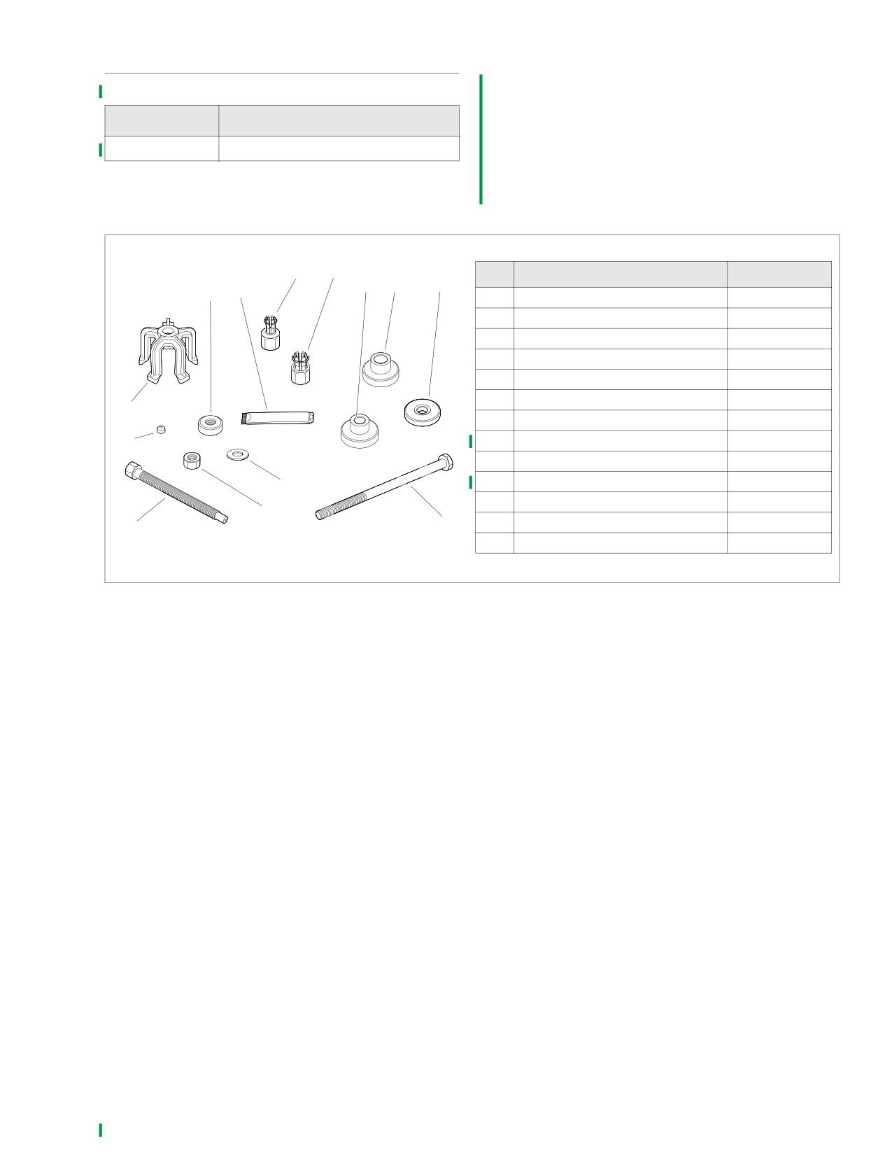
SEALED WHEEL BEARINGS
Inspection
1. Inspect the play of the wheel bearings by finger while
they are in the wheel. Rotate the inner bearing race and
check for abnormal noise. Make sure bearing rotates
PART NO.
SPECIALTY TOOL
smoothly.
HD-44060
Wheel Bearing Installer/Remover
2. Check wheel bearings and axle spacers for wear and
corrosion. Excessive play or roughness indicates worn
bearings. Replace bearings in sets only. See Removal
and Installation which follow.
x0440x2x
11
10
NO.
DESCRIPTION
PART NO.
9
8
7
13
12
1
Bridge
HD-44060-5
2
Steel ball
12547
3
Forcing screw
HD-44060-4
4
Nut
10210
5
Washer
12004
6
Threaded rod
280856
1
7
Support plate
HD-44060-1
2
8
Pilot, 1 in.
HD-44060-8
9
Pilot, 3/4 in.
HD-44060-6
10
Collet, 1 in.
HD-44060-7
5
11
Collet, 3/4 in.
HD-44060-3
4
12
Lubricant
J-23444A
6
3
13
Nice bearing
RS25100-200
Figure 2-13. Wheel Bearing Remover/Installer (Part No. HD-44060)
2006 Sportster: Chassis
2-19
HOME
Removal
x0356x2x
1.
If not already done, remove wheel from motorcycle. See
1
FRONT WHEEL Removal or REAR WHEEL Removal
under 2.4 WHEELS. On vehicles with a single front brake
2
caliper, remove hub plate from wheel on side opposite
front brake disc.
2.
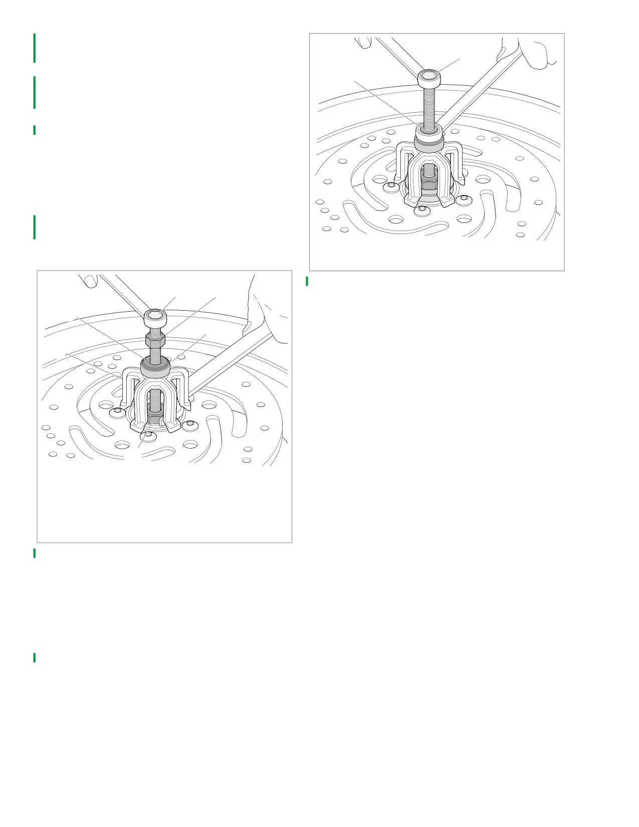
See Figure 2-14. Obtain WHEEL BEARING INSTALLER/
REMOVER and assemble.
a. Sparingly apply graphite lubricant to threads of forc-
ing screw (1) to prolong service life and ensure
smooth operation.
b. Install nut (2), washer (6) and Nice bearing (3) on
screw. Insert assembly through hole in bridge (5).
c. Drop ball bearing inside collet (4). Fasten collet and
ball bearing to forcing screw.
3.
Hold end of forcing screw and turn collet to expand
edges of collet.
1.
Forcing screw
2.
Nut
x0437x2x
Figure 2-15. Removing Wheel Bearing
1
2
6
3
5
4
1.
Forcing screw
2.
Nut
3.
Nice bearing
4.
Collet with ball bearing inside
5.
Bridge
6.
Washer
Figure 2-14. Assembling Removal Tool
4.
See Figure 2-15. When expanded collet has gripped
bearing edges, hold end of forcing screw (1) and turn the
nut (2) to remove bearing from wheel.
5.
Remove spacer from inside wheel hub.
6.
Repeat procedure for opposite side bearing. Discard
both bearings upon removal.
2-20
2006 Sportster: Chassis
HOME
2. Hold hex end of threaded rod and turn nut to install
Installation
wheel bearing. Bearing is fully seated when nut can no
NOTES
longer be turned. Remove tool.
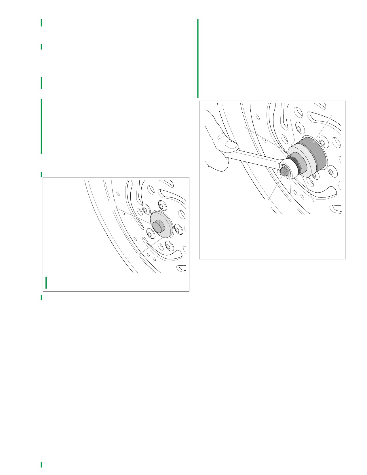
● When installing wheel bearings, use specialty tool
3. Install spacer inside wheel hub.
WHEEL BEARING INSTALLER/REMOVER.
4. Reverse tool and install opposite side wheel bearing.
● Always install first bearing on primary brake disc side. If
5. On cast front wheels with single brake caliper, apply two
front wheel has two brake discs, install bearing on the left
drops of LOCTITE THREADLOCKER 243 to hub plate
side first.
mounting screws. Install hub plate opposite brake disc
1.
See Figure 2-13. Obtain WHEEL BEARING INSTALLER/
and secure with screws. Tighten to 16-24 ft-lbs (21.7-
REMOVER and assemble.
32.6 Nm).
a. Sparingly apply graphite lubricant to threads of
threaded rod (6) to prolong service life and ensure
smooth operation.
x0358x2x
4
b. See Figure 2-16. Place threaded rod (1) through
5
support plate (2). Insert assembly through wheel.
6
c. See Figure 2-17. Lubricate outside of new wheel
bearing (4) with a light coat of ANTI-SEIZE LUBRI-
CANT. Place bearing on rod (1) with lettered side
facing out.
d. Install pilot (5), Nice bearing (6), washer (3) and nut
(2) over rod.
x0357x2x
1
1
2
3
1.
Threaded rod
2.
Nut
3.
Washer
4.
Wheel bearing
5.
Pilot
6.
Nice bearing
2
Figure 2-17. Installing Bearing
1.
Threaded rod
2.
Support plate
Figure 2-16. Assembling Installation Tool
2006 Sportster: Chassis
2-21
HOME
WHEEL LACING: 16 INCH RIM
2.5
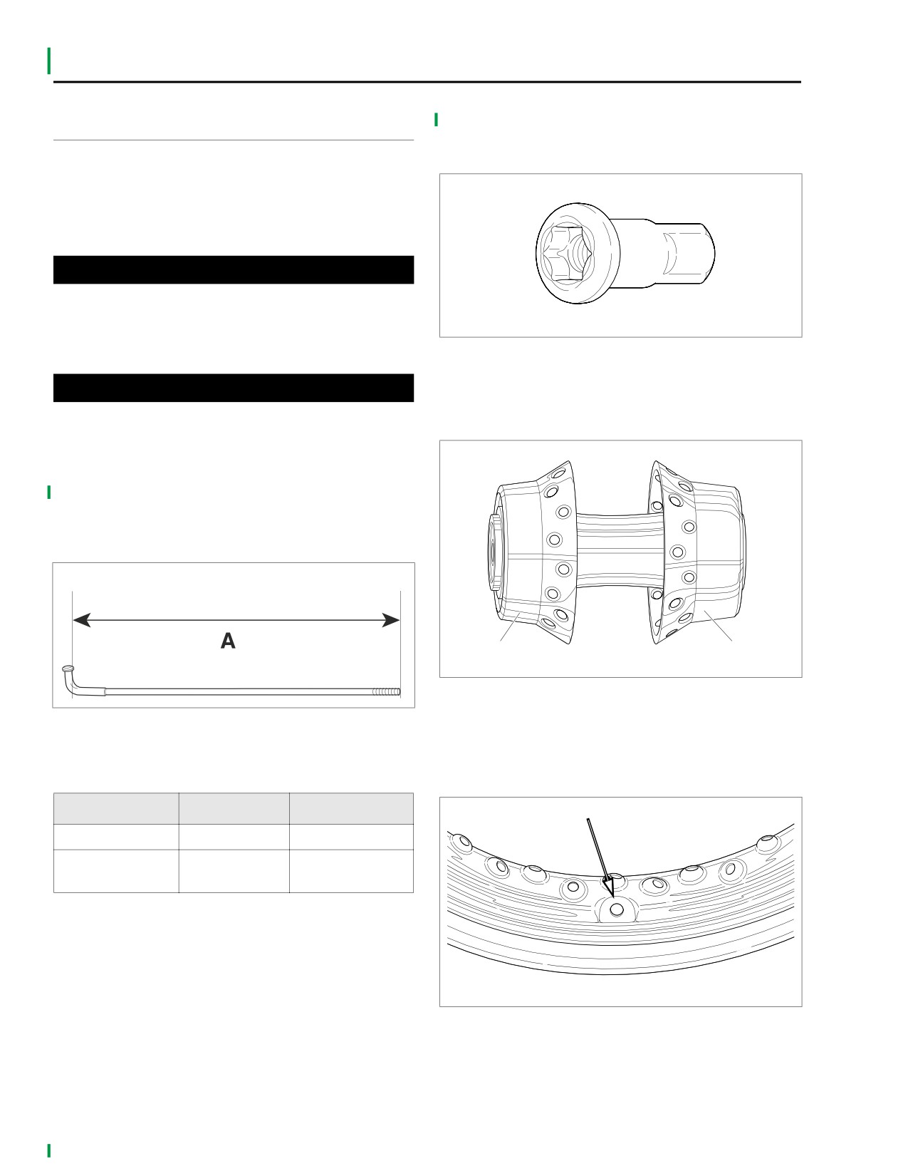
See Figure 2-19. T-30 I.P. (Torx Plus) head spokes are shown
GENERAL
below.
NOTE
If only rim is to be replaced, tape spokes together to hold
position on hub and remove spokes from rim. Install taped
x0049x2x
hub/spoke assembly to new rim and tighten spokes. Then
remove tape and true wheels.
1WARNING
Avoid using oils that attack or contribute to the deteriora-
tion of rubber materials. Use of unsuitable oils may lead
to premature tire failure, which could result in death or
serious injury.
Figure 2-19. Spoke Nipple
See Figure 2-20. The 16 inch laced wheel hub is shown
CAUTION
below.
Do not install incorrect spokes or spoke nipples on rim.
Steel laced rims use zinc plated spoke nipples. Chrome
aluminum profile laced rims use chrome plated spoke
x0364x2x
nipples.
See Figure 2-18. Measure spoke length (distance “A”). To
determine correct spoke length for type of rim used, refer to
Table 2-12.
d0759x2x
Narrow flange
Wide flange
brake side
sprocket side
Figure 2-20. 16-Inch Laced Wheel Hub
Figure 2-18. Spoke Length
See Figure 2-21. The new 16 inch laced wheel rim is shown
below. New rims can be identified by the “half moon” shape
around the valve stem hole.
Table 2-12. 16 In. Rim Spoke Length
Rim
IN.
MM.
x0365x2x
Steel laced
6.71-6.75
170.4-171.5
Chrome aluminum
6.88-6.92
174.8-175.8
profile laced
Figure 2-21. Valve Stem Hole
2-22
2006 Sportster: Chassis
HOME
PROCEDURE
x0441x2x
1.
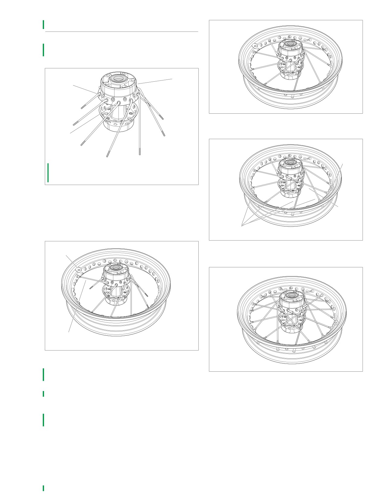
See Figure 2-22. Place hub on table with brake disc side
(narrow flange) (3) up. Insert a spoke in each hole of
lower row (1) as shown below. Angle spokes clockwise.
x0366x2x
3
2
Figure 2-24.
1
x0442x2x
Valve
stem
hole
1.
Lower row of spoke holes
2.
Upper row of spoke holes
3.
Brake disc side of hub (narrow flange)
Figure 2-22.
1
2
3
4
2.
See Figure 2-23. Position rim over the hub and spokes
First
with valve stem hole up. Using any lower row spoke,
spoke
place the first spoke into the rim hole to the left of the
valve stem hole on the upper half of the rim centerline.
Cross four
Figure 2-25.
x0367x2x
Valve
stem
hole
x0443x2x
First
spoke
Figure 2-23.
3.
See Figure 2-24. Install remaining lower row spokes, one
in every fourth hole.
Figure 2-26.
4.
See Figure 2-25. Place the first upper row spoke into the
hub as shown. Angle the spoke counterclockwise cross-
ing four lower row spokes. The spoke must enter the
hole to the right of the valve stem hole.
5.
See Figure 2-26. Install the nine remaining upper row
spokes, one into every fourth remaining hole above the
rim centerline. This completes spoke installation on
brake disc side.
2006 Sportster: Chassis
2-23
HOME
6.
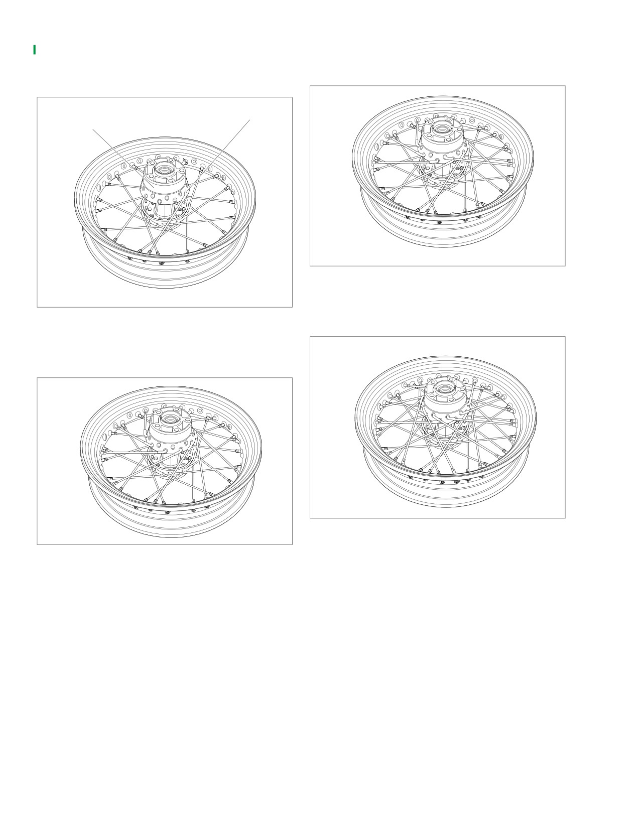
See Figure 2-27. Turn wheel assembly over so the
8. See Figure 2-29. Insert any upper row spoke into hub
sprocket side (wide flange) faces up. Place any lower row
and angle spoke counterclockwise. Place spoke into
spoke into hub. Angle spoke clockwise and place into rim
appropriate rim hole.
hole angled to accept it.
x0369x2x
Wide
Lower
flange
row
sprocket
spoke
side
Figure 2-29.
x0444x2x
9. See Figure
2-30. Install remaining nine upper row
spokes.
Figure 2-27.
7.
See Figure 2-28. Place the remaining nine lower row
x0370x2x
spokes, angled clockwise, into hub and rim.
x0368x2x
Figure 2-30.
Figure 2-28.
10. Tighten spoke nipples to 40-50 in-lbs (4.5-5.7 Nm).
11. True the wheel. See 2.8 TRUING LACED WHEELS.
2-24
2006 Sportster: Chassis
HOME
WHEEL LACING: 19 INCH RIM
2.6
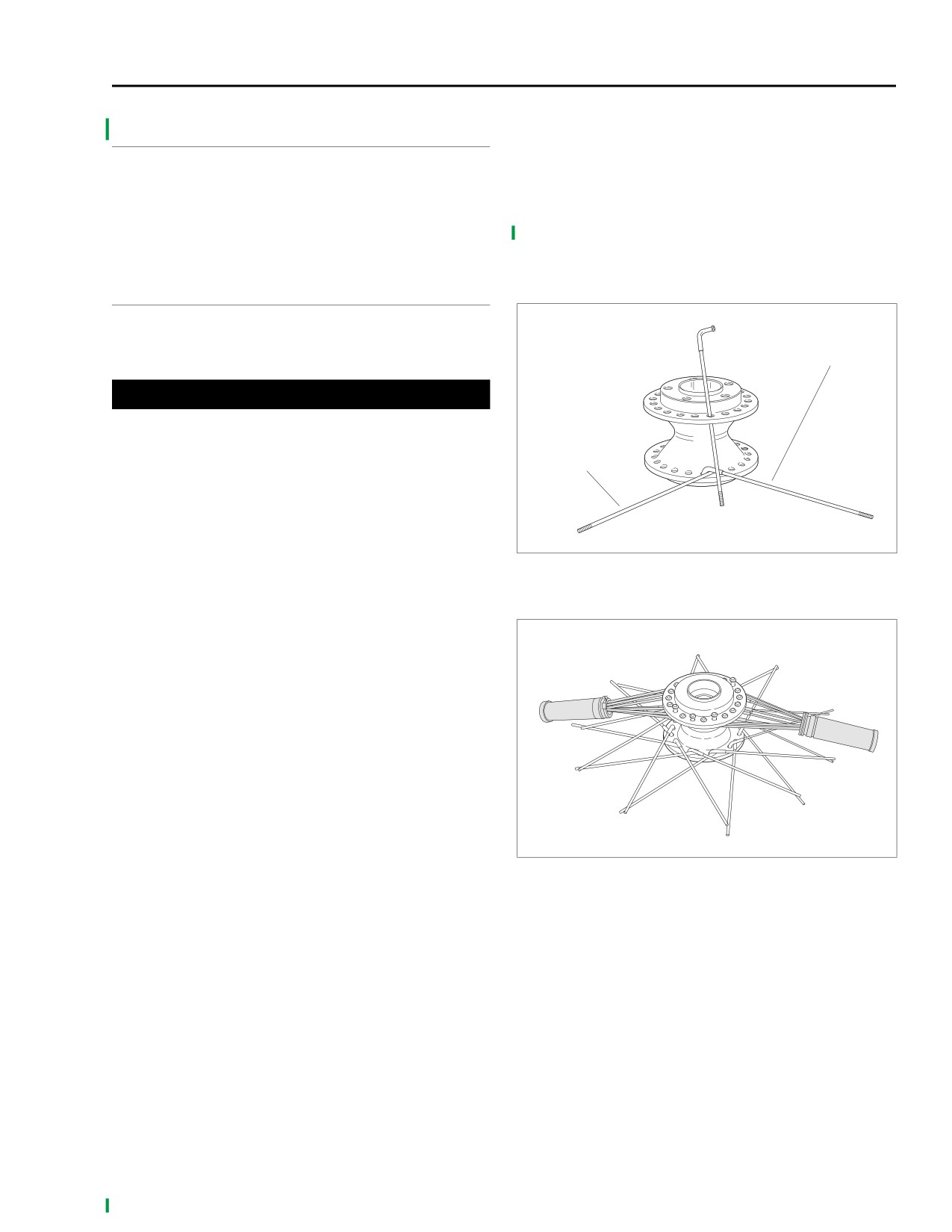
7. Swing all bottom flange outer spokes (short-head) clock-
GENERAL
wise.
8. Swing the inner spokes (long-head) counterclockwise,
NOTE
crossing over the outer spokes (short-head). Angle all
If only rim is to be replaced, tape spokes together to hold
spokes as far as they will go without overlapping the next
position on hub and remove spokes from rim. Install taped
LIKE spoke. For instance, swing an inner spoke (long-
hub/spoke assembly to new rim and tighten spokes. Then
head) counterclockwise across four spokes as far as it
remove tape and true wheels.
will go before crossing another inner spoke (laced in a
cross-four pattern).
PROCEDURE
x0371x2x
1.
Divide spokes into two groups.
Inner spoke
● Inner spokes have long heads.
(long head)
● Outer spokes have short heads.
1WARNING
Avoid using oils that attack or contribute to the deteriora-
Outer spoke
tion of rubber materials. Use of unsuitable oils may lead
(short head)
to premature tire failure, which could result in death or
serious injury.
2.
Lubricate spoke threads and nipple shoulders with tire
mounting lubricant.
3.
See Figure 2-31. Place hub on bench with the brake disc
side up. Insert one outer spoke (short-head) into any bot-
Figure 2-31. Lacing 19-in. Wheel Hub
tom flange hole and swing it clockwise. Insert an inner
spoke (long-head) in the next hole to the left of the outer
spoke. Swing the inner spoke counterclockwise over the
outer spoke.
x0372x2x
4.
Find the hole in the upper flange directly above the two
spokes just inserted. This hole uses a long head inner
spoke. Insert inner spoke into the hole on the upper
flange that directly bisects the two spokes in the bottom
flange. Insert all remaining spokes in upper flange alter-
nating the inner and outer spokes.
5.
After one flange side is completed flip wheel hub upside
down and repeat to finish other flange.
6.
See Figure 2-32. With all forty spokes inserted in hub,
group all spokes on top flange into two bundles. Secure
each group with throttle grips to keep the spokes
together.
Figure 2-32. Bundling Top Spokes
2006 Sportster: Chassis
2-25
HOME
NOTES
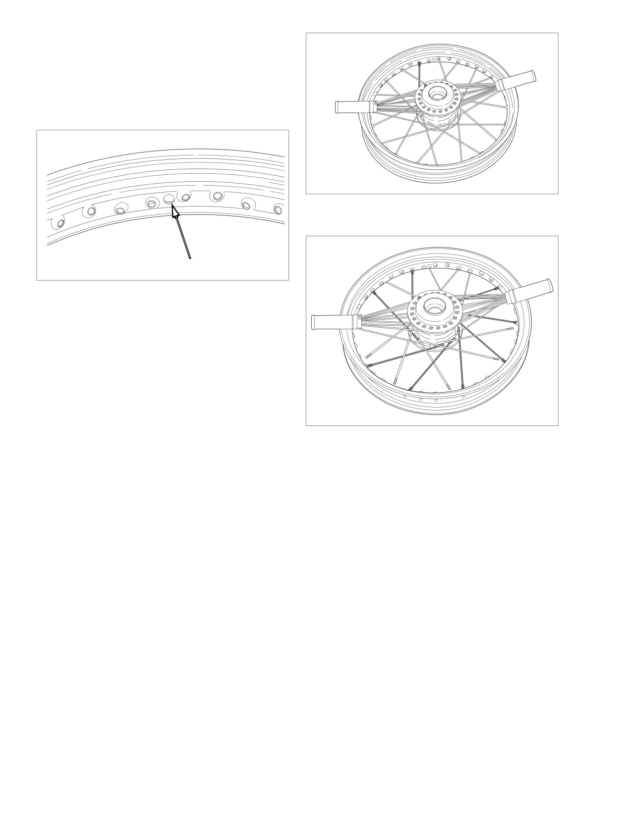
● All inside spokes lay over all outside spokes.
x0377x2x
● See Figure 2-33. The valve stem hole is centered on the
rim; you do not have to worry about choosing the correct
relationship between the rim and the hub.
9.
Center the rim over the hub assembly.
x0373x2x
Figure 2-34. Beginning Spoke-Bottom Flange Outer
x0374x2x
Figure 2-33. Valve Stem Hole Location
NOTE
It is recommended that you lace the first spoke next to the
valve stem hole. When lacing your first spoke, place spoke
nipples through several rim holes to determine the correct
lacing direction. Only one spoke will fit into the spoke nipple
correctly. When connecting the spoke to the spoke nipple, fin-
ger tighten two to three threads.
10. Straighten any spokes that were accidentally bumped or
moved on the bottom flange.
11. Work with the bottom flange of outer spokes (short-head)
Figure 2-35. Completed Spokes-Bottom Flange Outer
first.
12. See Figure 2-34. Using the spoke alignment method dis-
cussed previously, Locate a hole pointing downward and
outward toward the bottom flange of outer spokes (short-
head).
a. Verify outer spoke (short-head) reaches the spoke
nipple and secure spoke loosely by hand. Skip three
rim holes and repeat lacing. Follow pattern to com-
plete bottom flange outer spokes (short-head).
b. See Figure 2-35. Once you have completed lacing
the bottom row of outer spokes (short-head) double
check for three empty holes in between each spoke.
2-26
2006 Sportster: Chassis
HOME
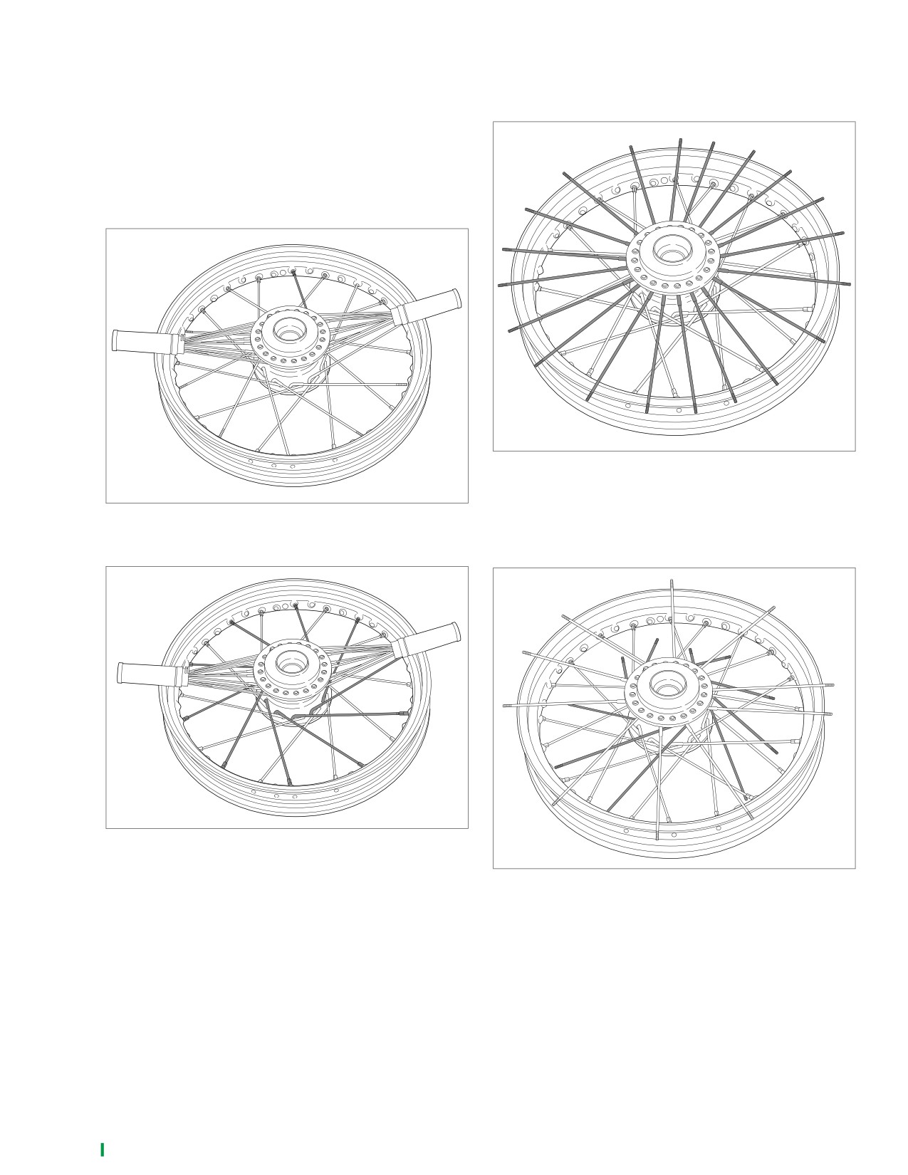
13. Work with bottom flange inner spokes (long-head) next.
14. See Figure 2-38. Undo each top bundle and fan the
Choose a beginning spoke closest to the valve stem
spokes out (in a starburst pattern) around the top rim
hole.
edge.
a. See Figure
2-36. Each inner spoke
(long-head)
crosses four outer spokes (short-head).
b. See Figure 2-37. Verify inner spoke reaches spoke
x0381x2x
nipple and secure spoke loosely by hand. Skip every
other hole and repeat lacing. Follow pattern to com-
plete bottom row inner spokes (long-head).
x0375x2x
Figure 2-38. Fanning Top Flange Spokes
15. See Figure 2-39. Point all the top flange inner spokes
Figure 2-36. Beginning Spoke-Bottom Flange Inner
(long-head) clockwise one at a time leaving the outer
spokes (short-head) resting on the rim.
x0378x2x
x0376x2x
Figure 2-37. Completed Spokes-Bottom Flange Inner
Figure 2-39. Setting Top Flange Inner Spokes
NOTE
Do not knock outer spokes (short-head) under inner spokes
(long-head) or they will be trapped underneath the inner row
of spokes.
2006 Sportster: Chassis
2-27
HOME
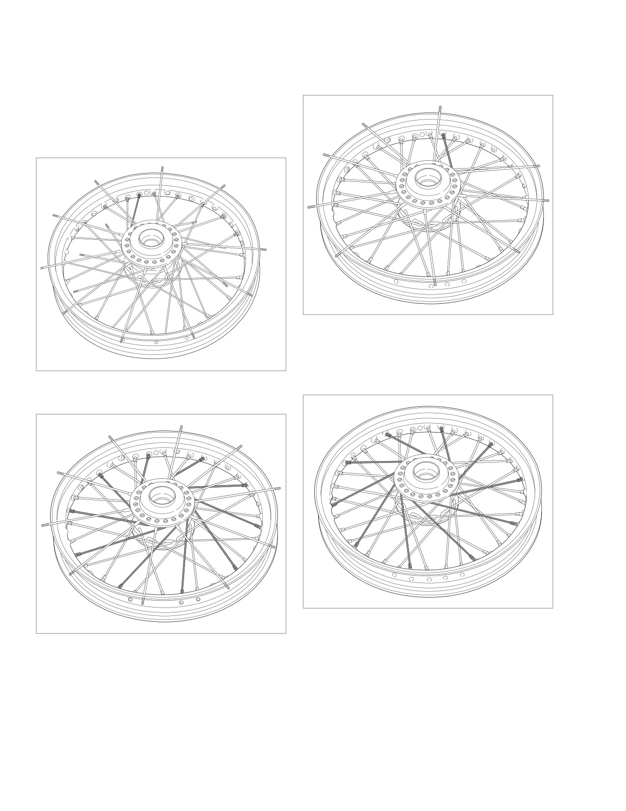
16. Using the spoke alignment method discussed previously,
17. See Figure 2-42. Finish with top flange outer spokes
choose a beginning spoke closest to the valve stem hole.
(short-head). Point the top flange outer spokes (short-
Start with top flange inner spokes (long-head) first.
head) counterclockwise and make sure each one
crosses four inner spokes before securing it to the rim.
a. See Figure 2-40. Verify spoke reaches spoke nipple
and secure spoke by hand. Follow pattern to com-
plete top flange inner spokes (long-head).
x0382x2x
b. See Figure 2-41. Once you have completed the top
flange of inner spokes (long-head) double check for
one empty hole after every third spoke.
x0379x2x
Figure 2-42. Beginning Spoke-Top Flange Outer
18. See Figure 2-43. Verify spoke reaches spoke nipple and
secure spoke by hand. Follow pattern to complete top
flange outer spokes (short-head).
Figure 2-40. Beginning Spoke-Top Flange Inner
x0383x2x
x0380x2x
Figure 2-43. Completed Spokes-Top Flange Outer
Figure 2-41. Completed Spokes-Top Flange Inner
19. Tighten spoke nipples to 40-50 in-lbs (4.5-5.7 Nm).
20. True the wheel. See 2.8 TRUING LACED WHEELS.
2-28
2006 Sportster: Chassis
HOME
WHEEL LACING: 21 INCH RIM
2.7
GENERAL
PROCEDURE
1.
Divide spokes into two groups.
NOTE
If only rim is to be replaced, tape spokes together to hold
● Inner spokes have long heads.
position on hub and remove spokes from rim. Install taped
● Outer spokes have short heads.
hub/spoke assembly to new rim and tighten spokes. Then
NOTE
remove tape and true wheels.
See
Figure 2-45. The spoke holes in the 21-inch wheel
hub
are
staggered, alternating between inner holes
(nearer
hub
center) and outer holes (nearer hub edge).
1WARNING
Avoid using oils that attack or contribute to the deteriora-
tion of rubber materials. Use of unsuitable oils may lead
to premature tire failure, which could result in death or
serious injury.
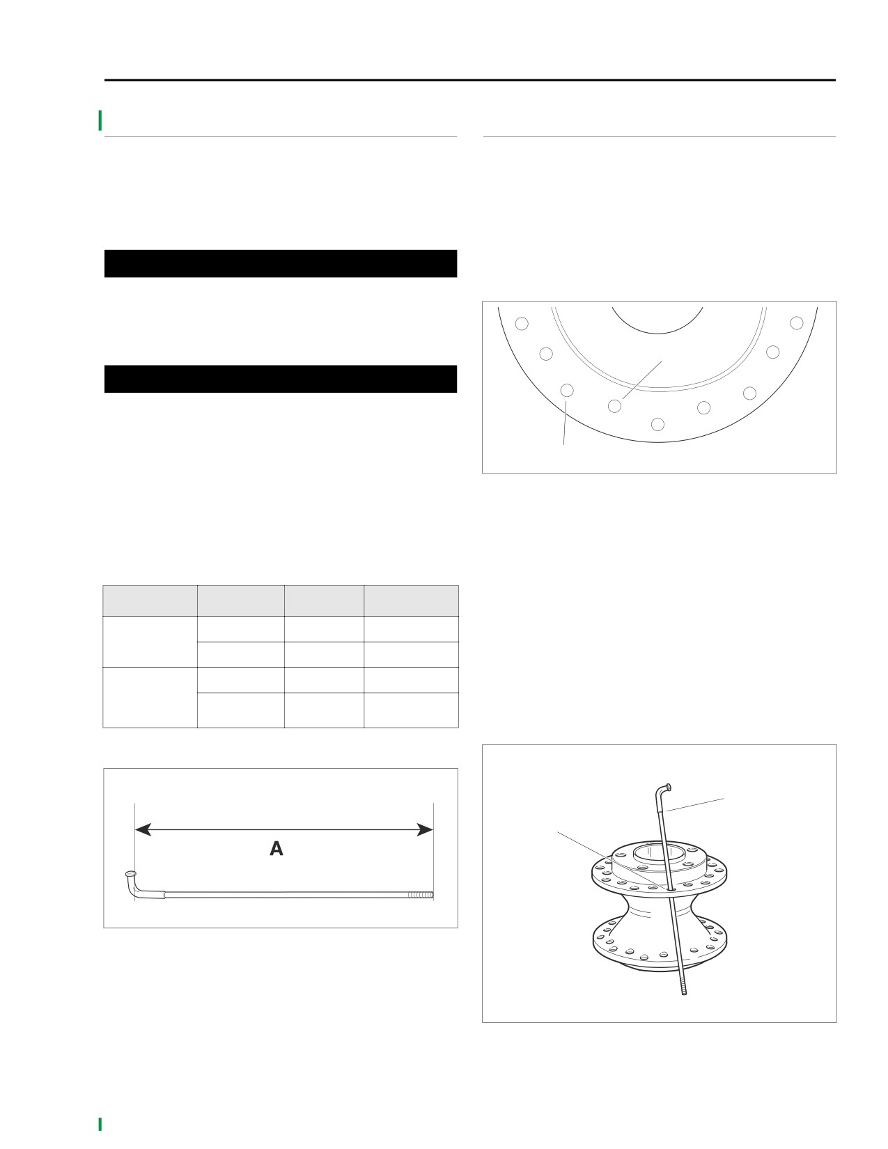
Inner spoke hole
CAUTION
Do not install incorrect spokes or spoke nipples on rim.
Steel laced rims use zinc plated spoke nipples. Chrome
aluminum profile laced rims use chrome plated spoke
nipples.
Outer spoke hole
x0636x2x
See Figure 2-44. Measure distance “A” to determine spoke
Figure 2-45. Spoke Hole Pattern - 21-in. Wheel Hub
length. Refer to Table 2-13. to determine correct spoke length
for type of rim used.
2. Lubricate spoke threads and nipple shoulders with tire
mounting lubricant.
3. See Figure 2-46. Place hub on bench with the brake disc
Table 2-13. 21 In. Rim Spoke Length
side up. Insert one outer spoke (short-head) into an
outer top flange hole and swing it counterclockwise.
RIM
SPOKE
IN.
MM
Insert an inner spoke (long-head) in the next hole to the
right of the outer spoke. Swing the inner spoke clockwise
Long head
9.36-9.40
237.7-238.8
under the outer spoke.
Steel laced
Short head
9.40-9.44
238.8-239.8
4. In the same way, insert all remaining spokes in brake-
side flange alternating inner and outer spokes.
Chrome
Long head
9.48-9.52
240.8-241.8
5. After brake-side flange is completed flip wheel hub over
aluminum
Short head
9.48-9.52
240.8-241.8
and repeat procedure on other flange.
profile laced
x0637x2x
Outer spoke
d0759x2x
(short head)
Outer
spoke
hole
Figure 2-44. Measuring Spoke Length
Figure 2-46. Lacing 21-in. Wheel Hub
2006 Sportster: Chassis
2-29