Harley Davidson 2006 Sportster XLH MODELS. Service Manual - page 2
HOME
5.
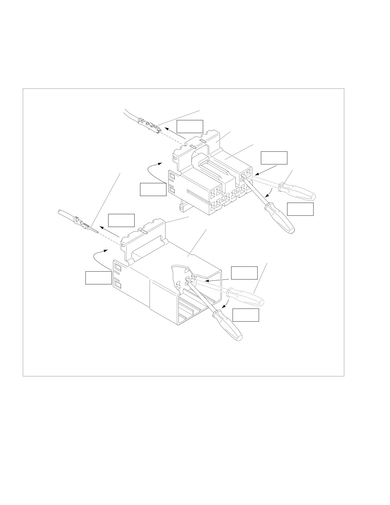
See Figure B-2. With the flat side against the terminal,
NOTE
insert the pick tool (Snap-On TT600-3) into the cavity
An Electrical Terminal Crimp Tool (Part No. HD-41609) is
until it stops.
used to install Amp Multi-lock pin and socket terminals on
wires. If new terminals must be installed, see
Crimping
6.
Pivot the end of the pick away from the terminal and gen-
tly tug on wire to pull terminal from chamber. Do not tug
Instructions on the next page.
on the wire until the tang is released or the terminal will
be difficult to remove. A “click” is heard if the tang is
engaged but then inadvertently released. Repeat the
step without releasing the tang.
x0325x7x
4
Step 4
3
2
Step 2
1
6
Step 1
Step 3
3
Step 4
5
1
Step 2
Step 1
Step 3
1.
Pick tool
2.
Socket housing
3.
Secondary lock open
4.
Socket terminal
5.
Pin housing
6.
Pin terminal
Figure B-2. Amp Multi-lock Connector
B-2
2006 Sportster: Appendix B
HOME
2. Gently tug on wire end to verify that the terminal is
INSTALLING
locked in place and will not back out of chamber.
SOCKET/PIN TERMINALS
3. Rotate the hinged secondary lock inward until tabs fully
engage latches on both sides of connector.
NOTE
4. Insert the socket housing (plug) into the pin housing
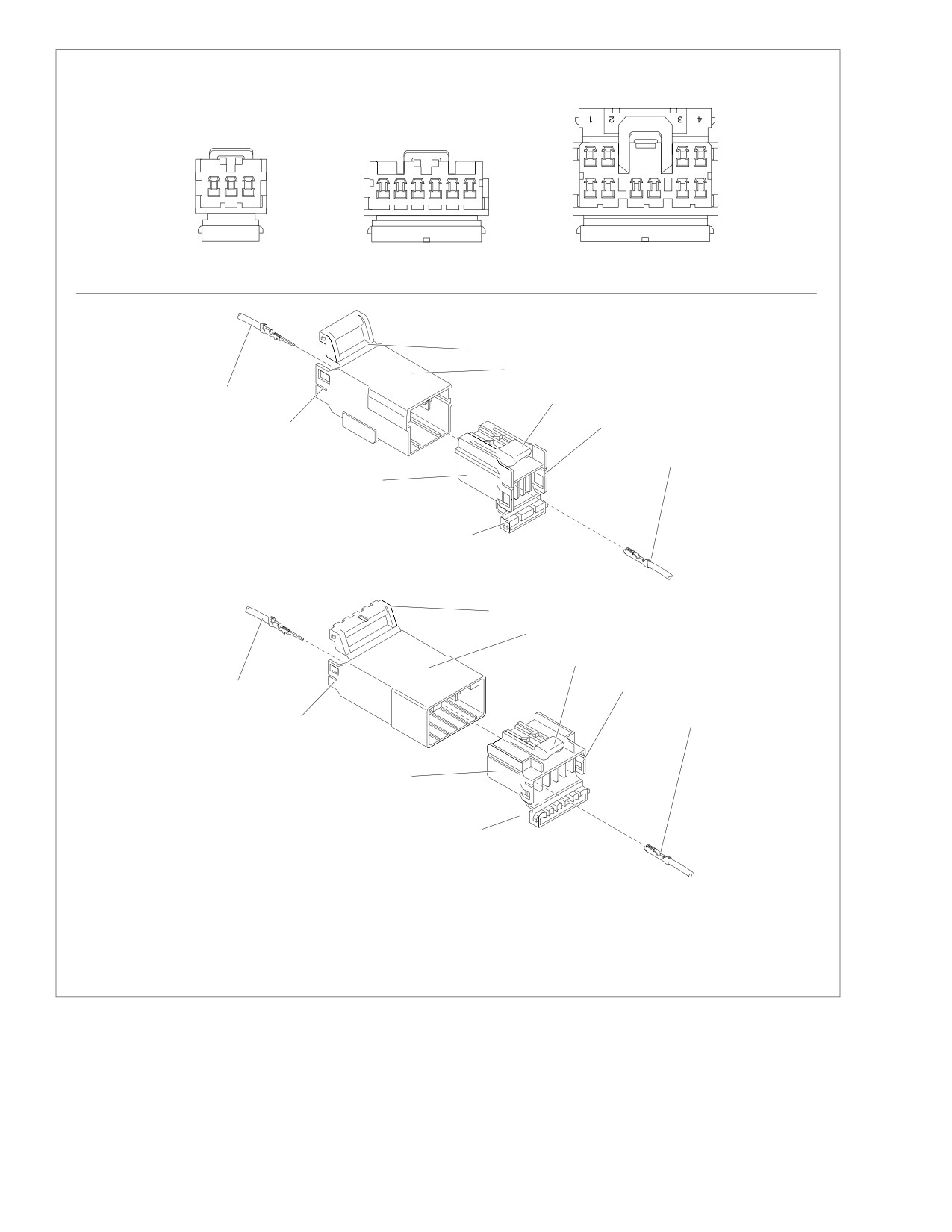
See Figure B-3. For wire location purposes, numbers are
(receptacle) until it snaps in place.
stamped into the secondary locks of both the socket and pin
5. Install connector on retaining device, either attachment
housings.
or rosebud clip.
1.
From the secondary lock side of the connector, insert the
terminal into its respective numbered chamber until it
snaps in place. For proper fit, the slot in the terminal
must face the tang in the chamber.
NOTE
The tang in the chamber engages the slot to lock the terminal
in position. On the pin side of the connector, tangs are posi-
tioned at the bottom of each chamber, so the slot in the pin
terminal
(on the side opposite the crimp tails) must face
downward. On the socket side, tangs are at the top of each
chamber, so the socket terminal slot (on the same side as the
crimp tails) must face upward. Up and down can be deter-
mined by the position of the release button (used to separate
the pin and socket halves), the button always being the top of
the connector.
2006 Sportster: Appendix B
B-3
HOME
x0326x7x
Secondary Locks Open
3-place
6-place
10-place
connector
connector
connector
– AMP
- AMP
1
2
3
1
2
3
4
5
6
5
6
7
8
9
10
Numbers Stamped on Secondary Locks for Wire Color Locations (Socket Housings Shown)
x0327x7x
5
4
3
7
2
2
1
6
5
x0328x7x
5
4
3
2
7
1
6
6
5
1.
Socket terminal
2.
Latch
3.
Button
4.
Pin housing
5.
Secondary lock open
6.
Socket housing
7.
Pin terminal
Figure B-3. 3-Place and 6-Place Amp Multi-lock Connectors
B-4
2006 Sportster: Appendix B
HOME
4. Strip lead removing 5/32 inch (4 mm) of insulation. Insert
CRIMPING INSTRUCTIONS
wires between crimp tails until ends make contact with
locking bar. Verify that wire is positioned so that short
1.
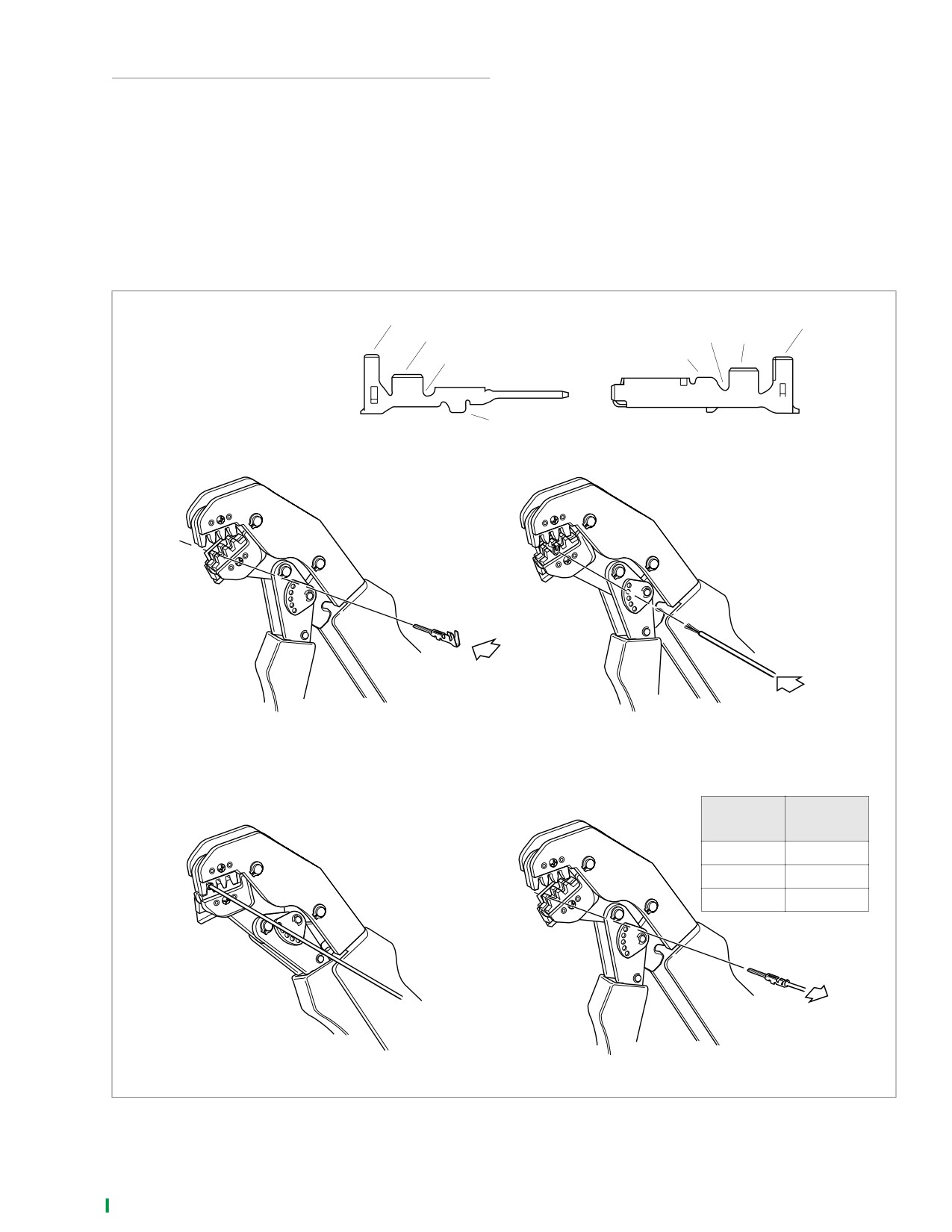
See Figure B-4. Squeeze the handles to cycle the crimp
pair of crimp tails squeeze bare wire strands, while long
tool (Part No. HD-41609) to the fully open position.
pair folds over insulation material.
2.
Raise locking bar by pushing up on bottom flange. With
5. Squeeze handle of crimp tool until tightly closed. Tool
the crimp tails facing upward, insert contact (socket/pin)
automatically opens when the crimping sequence is
through locking bar, so that the closed side of the contact
complete. Raise up locking bar and remove contact.
rests on the front nest (concave split level area of the
6. Inspect the quality of the core and insulation crimps. Dis-
crimp tool).
tortion should be minimal.
3.
Release locking bar to lock position of contact. When
correctly positioned, the locking bar fits snugly in the
space at the front of the core crimp tails.
1.
Insulating crimp tail
1
1
2.
Core crimp tail
2
3
2
3.
Locking bar groove
3
4
4.
Tang slot
4
1.
Raise locking bar and seat contact
2.
Insert stripped lead until it
on front nest of crimp tool. Release
contacts locking bar.
locking bar
GAUGE
CRIMPTOOL
WIRE
NEST
20
Front
16
Middle
18
Rear
3.
Close and squeeze crimp tool.
4.
Raise locking bar and remove contact.
d0246x8x
Figure B-4. Amp Multilock Crimping Procedure
2006 Sportster: Appendix B
B-5
HOME
DEUTSCH ELECTRICAL CONNECTORS
B.2
GENERAL
REMOVING/INSTALLING SOCKETS
The XL models utilize Deutsch DT and DTM Series Electrical
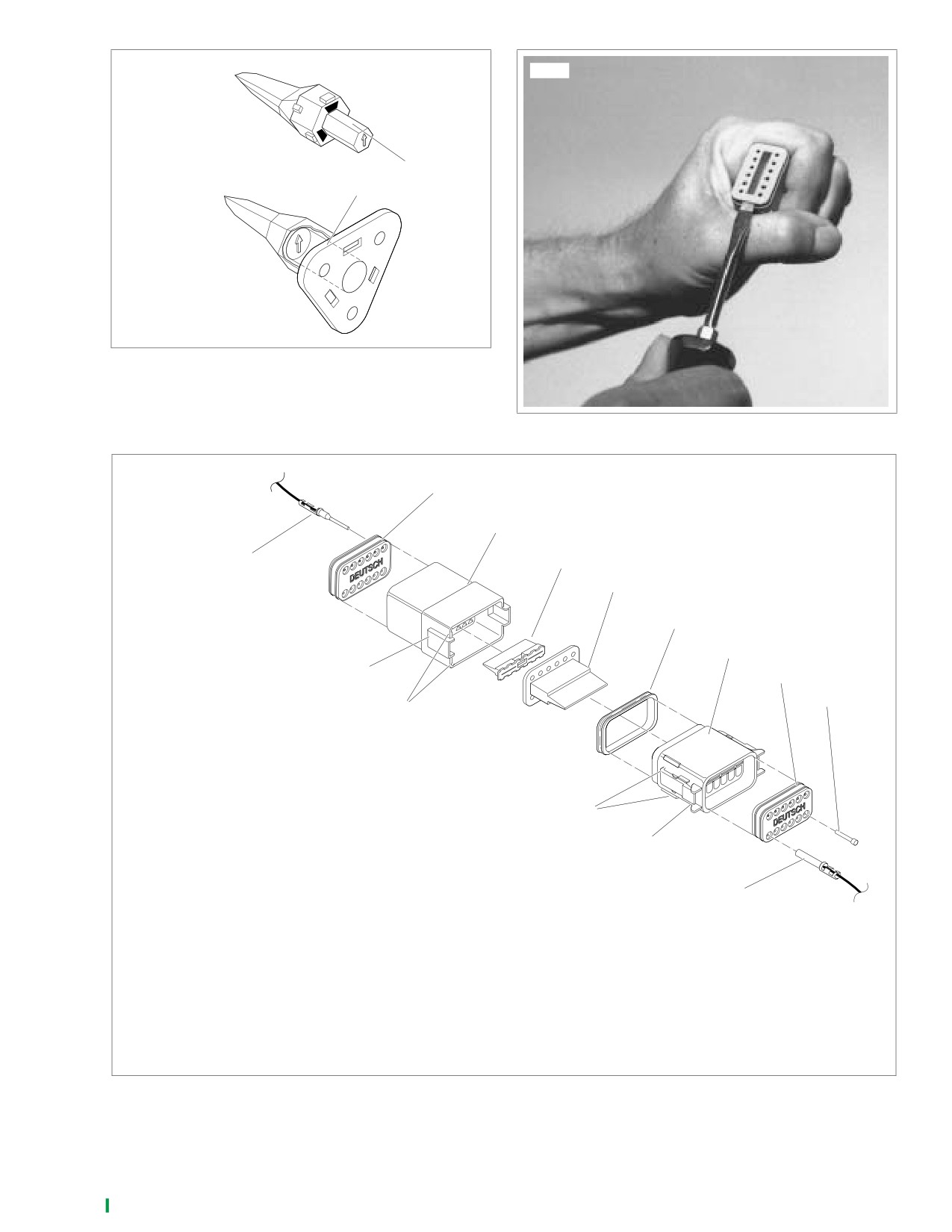
1. See Figure B-6. Remove the secondary locking wedge.
Connectors. The Deutsch Connector features a superior seal
Insert the blade of a small screwdriver between the
to protect electrical contacts from dirt and moisture in harsh
socket housing and locking wedge in line with the groove
environments. The connector also provides better pin reten-
(in line with the pin holes if the groove is absent). Turn
tion than previous connectors.
the screwdriver 90 degrees to pop the wedge up.
See Figure B-7. A 12-pin connector is illustrated to show the
2. Gently depress terminal latches inside socket housing
various parts of the Deutsch connector. The following instruc-
and back out sockets through holes in rear wire seal.
tions may be followed for all 2-pin through 12-pin Deutsch
NOTE
connectors.
An Electrical Terminal Crimp Tool (Part No. HD-39965) is
Socket housing: alignment tabs and/or external latch, sec-
used to install Deutsch pin and socket terminals on wires. If
ondary locking wedge, internal seal, wire seal, seal pin.
new terminals must be installed, follow the instructions
NOTE
included with the crimping tool or see Crimping Instructions in
Seal pins or plugs are installed in the wire seals of unused pin
this section.
and socket locations. If removed, seal pins must be replaced
3.
Fit rear wire seal into back of socket housing, if removed.
to maintain the integrity of the environmental seal.
Grasp socket approximately 1 inch (25.4 mm) behind the
Pin housing: alignment grooves and/or external latch cover,
contact barrel. Gently push sockets through holes in wire
attachment clip, secondary locking wedge, wire seal, seal pin.
seal into their respective chambers. Feed socket into
chamber until it “clicks” in place. Verify that socket will not
back out of chamber; a slight tug on the wire will confirm
REMOVING/DISASSEMBLING
that it is properly locked in place.
4.
Install internal seal on lip of socket housing, if removed.
Attachment clips are attached to the pin housings of most
Insert tapered end of secondary locking wedge into
connectors. The clips are then attached to T-studs on the
socket housing and press down until it snaps in place.
motorcycle frame. T-studs give positive location to electrical
The wedge fits into the center groove within the socket
connectors and wire harness. Consistent location reduces
housing and holds the terminal latches tightly closed.
electrical problems and improves serviceability.
1.
Push the connector toward the rear to disengage small
NOTES
end of slot on attachment clip from T-stud. Lift connector
●
See Figure B-5. While rectangular wedges do not require
off T-stud.
a special orientation, the conical secondary locking
2.
Depress the external latch(es) on the socket housing
wedge of the 3-pin connector must be installed with the
side and use a rocking motion to separate the pin and
arrow pointing toward the external latch.
socket halves. Two-, three-, four- and six-pin Deutsch
●
If the secondary locking wedge does not slide into the
connectors have one external latch, while eight- and
installed position easily, verify that all terminals are fully
twelve-pin connectors have two, both of which must be
installed in the socket housing. The lock indicates when
pressed simultaneously to separate the connector
terminals are not properly installed by not entering its
halves.
fully installed position.
NOTE
With few exceptions, the socket housing can always be found
on the accessory side, while the pin side of the connector is
plumbed to the wiring harness.
B-6
2006 Sportster: Appendix B
HOME
x0014a7x
4566
Pin Housing
Arrow points to
external latch
Socket
Housing
Figure B-5. 3-pin Locking Wedge Orientation
Figure B-6. Remove Secondary Locking Wedge
X0047X7X
13
12
9
14
8
7
4
3
11
2
10
Socket Side
1.
Socket terminal
2.
Seal pin
3.
Wire seal
4.
Socket housing
6
5.
External latch
5
6.
Alignment tabs
7.
Internal seal
8.
Locking wedge
1
Pin Side
9.
Locking wedge
10. Alignment grooves
11. Latch cover
12. Pin housing
13. Wire seal
14. Pin terminal
Figure B-7. 12-pin Deutsch Connector (Exploded View)
2006 Sportster: Appendix B
B-7
HOME
NOTES
REMOVING/INSTALLING PINS
● Deutsch connectors are color coded for location pur-
poses. Those connectors associated with left side acces-
1.
Remove the secondary locking wedge. Use the hooked
sories, such as the front and rear left turn signals, are
end of a stiff piece of mechanics wire or a needle nose
gray. All other connectors, including those associated
pliers, whichever is most suitable.
with right side accessories, are black.
2.
Gently depress terminal latches inside pin housing and
● If it should become necessary to replace a plug or recep-
back out pins through holes in wire seal.
tacle, please note that the 8-pin and 12-pin gray and
NOTE
black connectors are not interchangeable. Since location
An Electrical Terminal Crimp Tool (Part No. HD-39965) is
of the alignment tabs differ between the black and gray
used to install Deutsch pin and socket terminals on wires. If
connectors, plugs or receptacles must be replaced by
new terminals must be installed, see Crimping Instructions in
those of the same color. If replacing both the socket and
this section.
pin halves, then the black may be substituted for the gray,
and vice versa. The socket and pin halves of all other
3.
Fit wire seal into back of pin housing. Grasp crimped pin
connectors are interchangeable, that is, the black may be
approximately 1 inch (25.4 mm) behind the contact bar-
mated with the gray, since the alignment tabs are absent
rel. Gently push pins through holes in wire seal into their
and the orientation of the external latch is the same.
respective numbered locations. Feed pin into chamber
until it “clicks” in place. Verify that pin will not back out of
3. Fit the attachment clip to the pin housing, if removed.
chamber; a slight tug on the wire will confirm that it is
Place large end of slot on attachment clip over T-stud on
properly locked in place.
frame; push assembly forward to engage small end of
slot.
4.
Insert tapered end of secondary locking wedge into pin
housing and press down until it snaps in place. The
wedge fits in the center groove within the pin housing
CRIMPING INSTRUCTIONS
and holds the terminal latches tightly closed.
NOTES
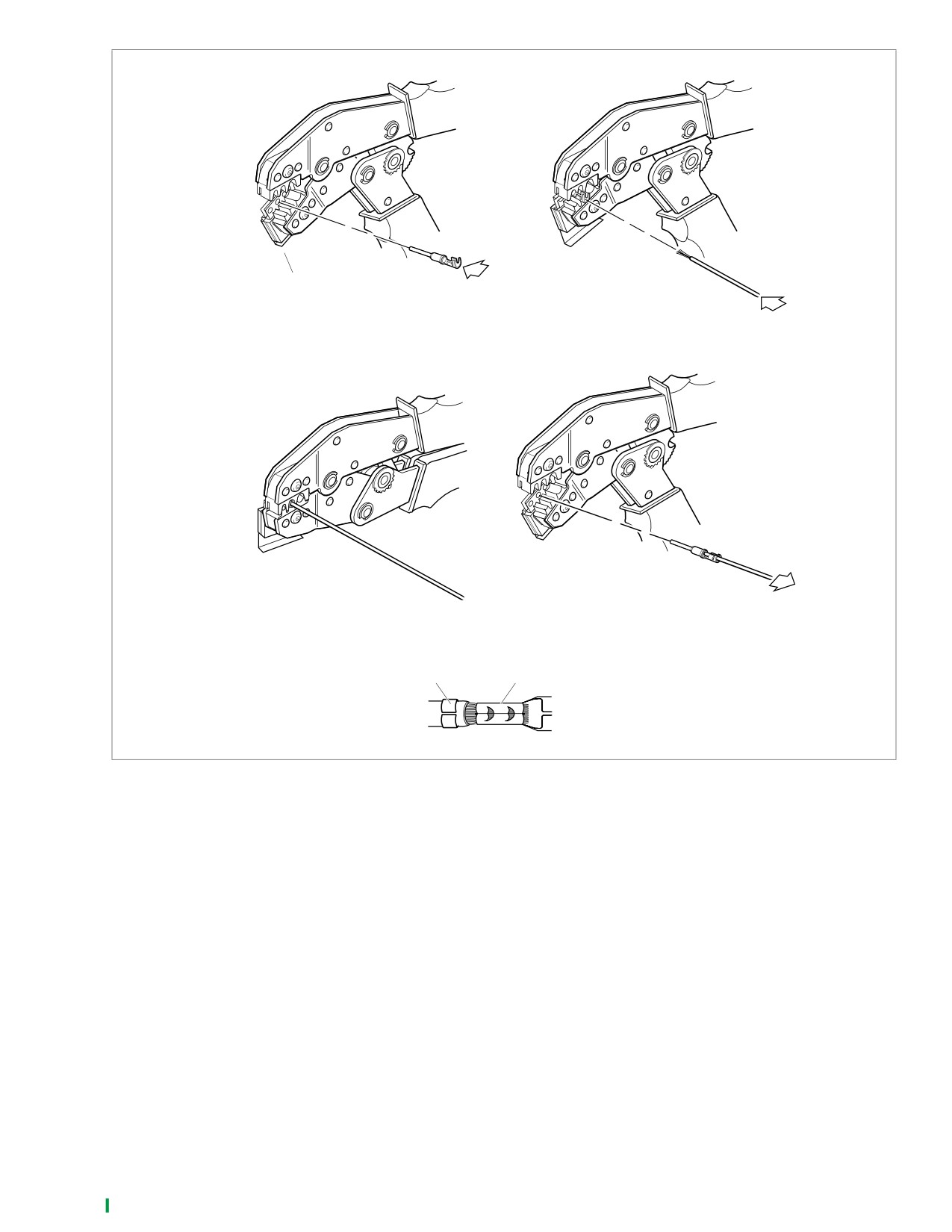
1. See Figure B-8. Squeeze the handles to cycle the crimp
● See Figure B-5. While rectangular wedges do not require
tool to the fully open position.
a special orientation, the conical secondary locking
2. Raise locking bar by pushing up on bottom flange. With
wedge of the 3-pin connector must be installed with the
the crimp tails facing upward and the rounded side of the
arrow pointing toward the external latch.
contact barrel resting on the concave split level area of
the crimp tool, insert contact (socket/pin) through middle
● If the secondary locking wedge does not slide into the
hole of locking bar.
installed position easily, verify that all terminals are fully
installed in the pin housing. The lock indicates when ter-
3. Release locking bar to lock position of contact. If the
minals are not properly installed by not entering its fully
crimp tails are slightly out of vertical alignment, the crimp
installed position.
tool automatically rotates the contact so that the tails
face straight upward. When correctly positioned, the
locking bar fits snugly in the space between the contact
ASSEMBLING/INSTALLING
band and the core crimp tails.
4. Strip lead removing 5/32 inch (3.96 mm) of insulation.
1.
Insert socket housing into pin housing until it snaps in
Insert wires between crimp tails until ends make contact
place. Two-, three-, four- and six-pin Deutsch connectors
with locking bar. Verify that wire is positioned so that
have one external latch on the socket half of the connec-
short pair of crimp tails squeeze bare wire strands, while
tor. To fit the halves of the connector together, the latch
long pair folds over insulation material.
on the socket side must be aligned with the latch cover
5. Squeeze handle of crimp tool until tightly closed. Tool
on the pin side.
automatically opens when the crimping sequence is
2.
For those connectors with two external latches (8-pin
complete. Raise up locking bar and remove contact.
and
12-pin), a different system is used to prevent
Inspect the quality of the core and insulation crimps. Distor-
improper assembly. Align the tabs on the socket housing
tion should be minimal.
with the grooves on the pin housing. Push the connector
halves together until the latches “click.” If latches do not
click (latch), press on one side of the connector until that
latch engages, then press on the opposite side to
engage the other latch.
B-8
2006 Sportster: Appendix B
HOME
d0250x8x
Locking bar
1.
Insert contact through middle
2.
Insert stripped lead until it
hole in locking bar.
contacts locking bar.
3.
Close and squeeze crimp tool
4.
Raise locking bar and remove
contact.
Insulation crimp
Core crimp
Figure B-8. Deutsch Crimping Procedure
2006 Sportster: Appendix B
B-9
HOME
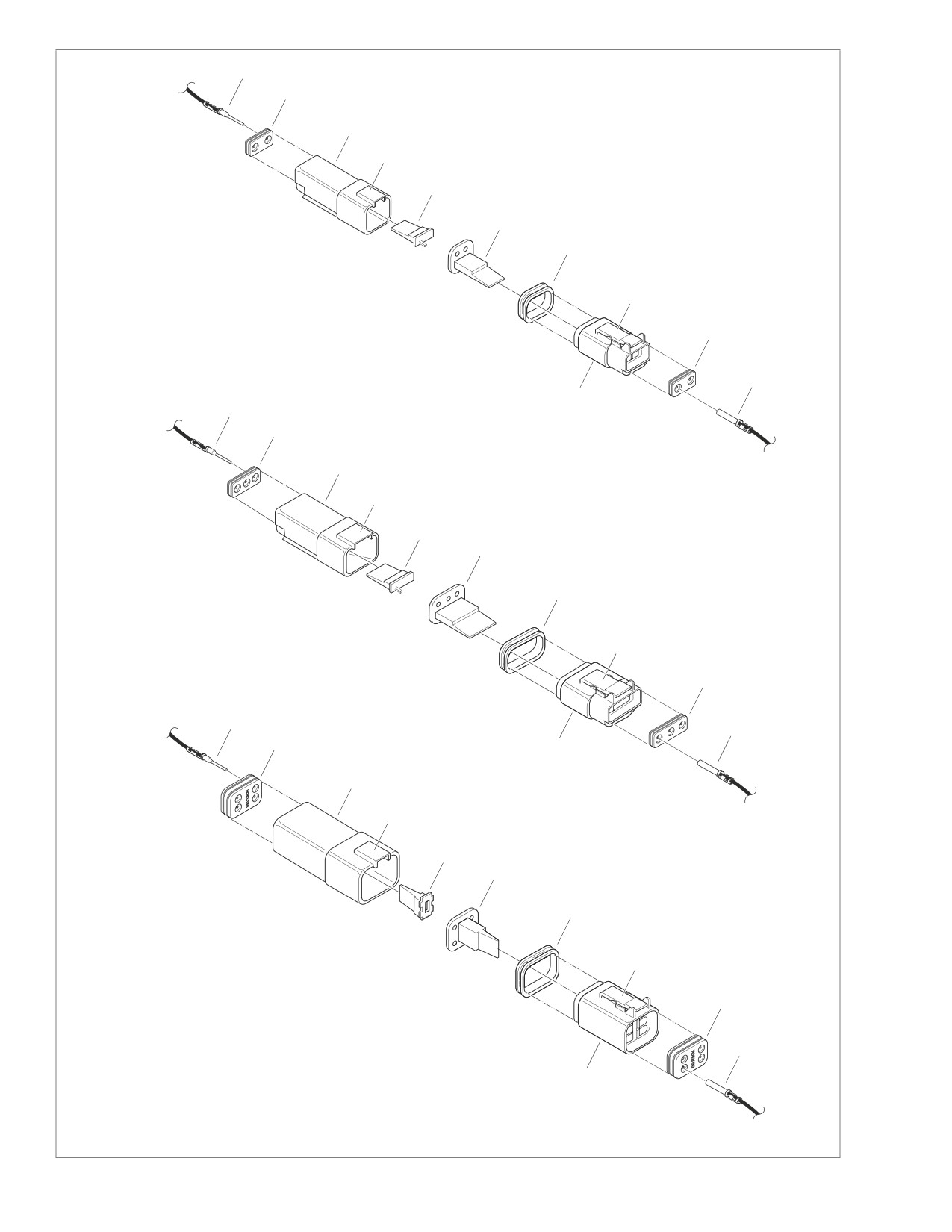
x0564x5x
11
10
9
8
7
2-pin connector
6
5
4
2
1
3
11
10
9
8
7
6
3-pin connector
5
4
2
11
1
10
3
9
8
7
6
5
4-pin connector
4
2
SOCKET SIDE
PIN SIDE
1.
Socket terminal
7.
Locking wedge
1
2.
Wire seal
8.
Latch cover
3.
Socket housing
9.
Pin housing
3
4.
External latch
10.
Wire seal
5.
Internal seal
11.
Pin terminal
6.
Locking wedge
Figure B-9. 2-Pin, 3-Pin and 4-Pin Deutsch Connectors
B-10
2006 Sportster: Appendix B
HOME
MINI-DEUTSCH CONNECTORS
B.3
GENERAL
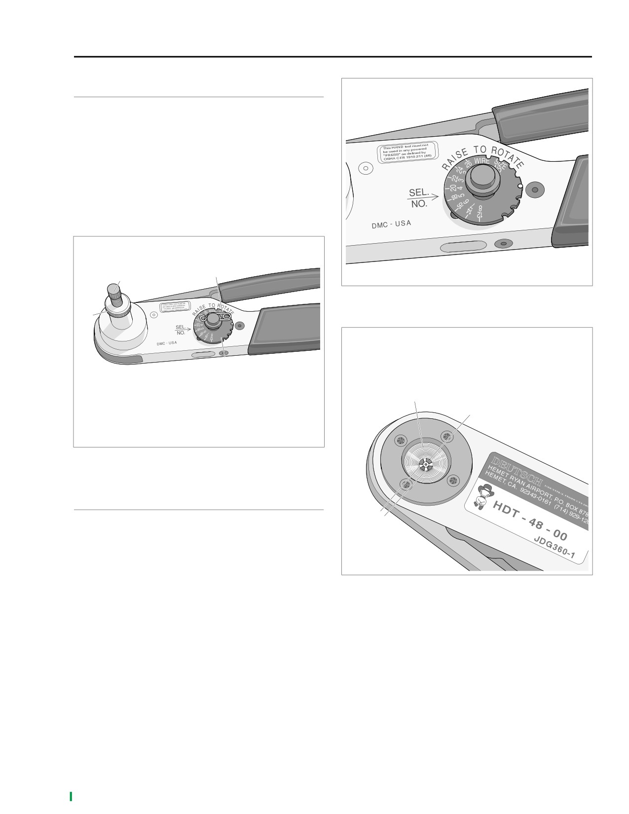
d0253x8x
For Size 20, 16 and 12 Contacts
Wire Range 26-12 AWG
NOTE
Mini-Deutsch connectors make use of a solid barrel contact
without crimp tails. As a result, a special TERMINAL CRIMP
TOOL (Part No. HD-42879) is needed to install pin and
socket terminals on wires. See Crimping Instructions below
for details.
d0252x8x
3
1
Figure B-11. Selector Knob
2
1. Indentor cover
2. Contact
3. Indentor points
4
1
1.
Adjusting screw
2
2.
Locknut
3.
Locking pin
4.
Selector knob
Figure B-10. Deutsch Solid Barrel Contact Crimp Tool
(Part No. HD-42879)
CRIMPING INSTRUCTIONS
1.
Squeeze the handles to cycle the crimp tool to the fully
3
open position.
2.
See Figure B-10. Remove locking pin (3) from selector
knob (4).
d0254x8x
3.
See Figure B-11. Raise selector knob and rotate until
selected wire size stamped on wheel is aligned with
Figure B-12. Indentor Points
“SEL. NO.” arrow.
4.
Loosen knurled locknut and turn adjusting screw clock-
5. Turn tool over and drop contact into indentor cover hole
wise (in) until it stops.
with the wire end out.
6. Turn adjusting screw counterclockwise (out) until contact
is flush with bottom of depression in indentor cover.
Tighten knurled locknut.
7. See Figure B-12. Slowly squeeze handles of crimp tool
until contact (2) is centered between indentor points (3).
2006 Sportster: Appendix B B-11
HOME
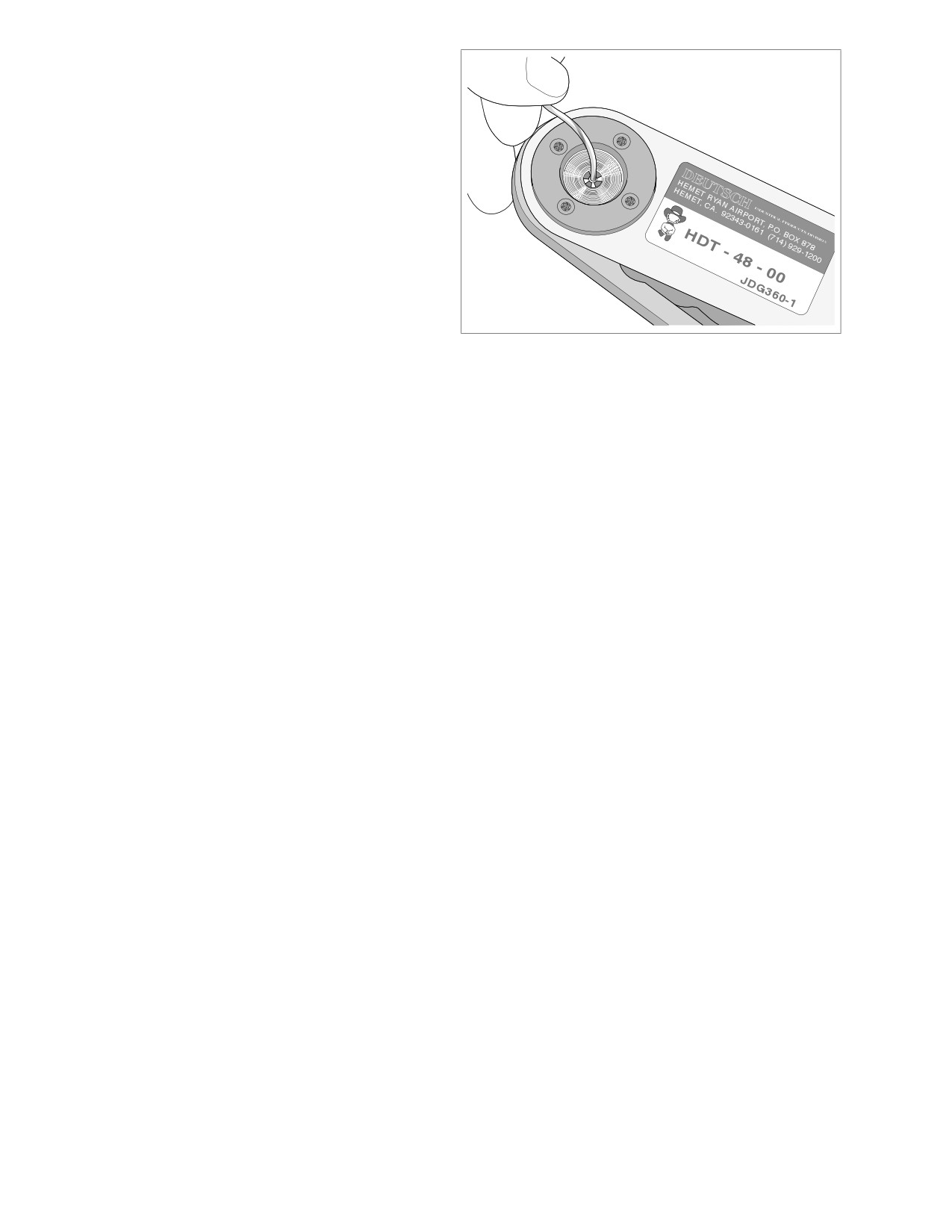
8.
Strip wire lead removing 1/4 in. (6.3 mm) of insulation.
9.
See Figure B-13. Insert bare wire strands into contact
barrel.
10. Squeeze handle of crimp tool until tightly closed. Tool
automatically opens when the crimping sequence is
complete.
11. Remove crimped contact from indentor.
12. Inspect the quality of the crimp. Verify that all wire
strands are in crimp barrel.
NOTE
Tool must be readjusted when changing contact size/type.
13. Install pin to lock position of selector knob.
d0255x8x
Figure B-13. Contact Barrel
B-12
2006 Sportster: Appendix B
HOME
PACKARD ELECTRICAL CONNECTORS
B.4
GENERAL
REMOVING PULL-TO-SEAT TERMI-
NALS/EXTERNAL LATCH TYPE
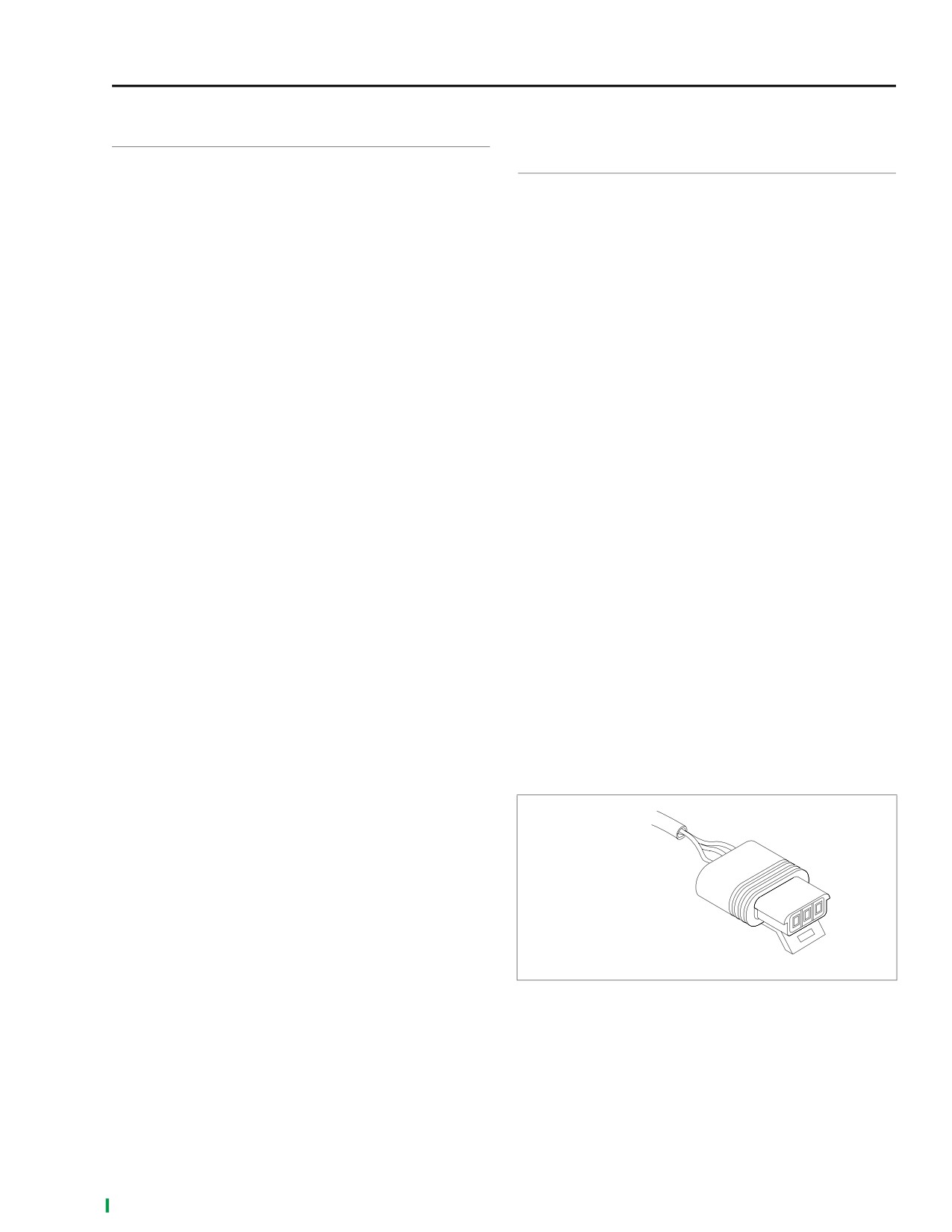
See Figure B-14. From a servicing standpoint, there are two
basic types of Packard electrical connectors, those with pull-
To remove a pull-to-seat terminal from connectors with exter-
to-seat terminals and those with push-to-seat terminals.
nal latches, proceed as follows:
Look into the mating end of the connector. If it appears that
1.
Remove the connector from the retaining device, if
the terminal can be extracted from this side, then it is proba-
present.
bly the pull-to-seat type.
2.
Bend back the external latch(es) slightly and separate
At least one Packard pull-to-seat terminal can be easily rec-
the pin and socket halves of the connector.
ognized by the presence of a locking ear. The ear engages a
3.
To free a pull-to-seat terminal from the connector hous-
slot in the connector housing and prevents the terminal from
ing, first look into the mating end of the connector to find
being removed from the wire end side of the connector. The
the locking tang. See A in Figure B-15. The tangs are
ear also acts as a strain relief in the event that the wires are
always positioned in the middle of the chamber and are
pulled and further inhibits movement of the terminal inside
on the same side as the external latch. On those connec-
the chamber.
tors with locking ears, the tang is on the side opposite
Unlike most connectors, where the terminals are pulled out
the ear.
the wire end of the connector, to remove the terminals from
4.
At a slight angle, gently insert the point of a one-inch
the pull-to-seat connectors, the terminal is pushed out the
(25.4 mm) safety pin about 1/8 inch (3.2 mm) down the
mating end of the connector. Once a new terminal is crimped
middle of the chamber and pivot the end of the pin
onto the end of the wire, the wire is pulled to draw the termi-
toward the terminal body. When a click is heard, remove
nal back inside the chamber of the connector housing.
the pin and repeat the procedure. See B in Figure B-15.
Packard pull-to-seat electrical connectors have an external
The click is the sound of the tang returning to the locked
latch to lock the pin and socket halves together.
position as it slips from the point of the pin. Pick at the
tang in this manner until the clicking stops and the pin
seems to slide in at a slightly greater depth than it had
previously. This is an indication that the tang has been
depressed.
NOTES
●
On those terminals that have been extracted on a previ-
ous occasion, no clicking sound may be heard when the
pin is pivoted to depress the tang, but proceed as if the
clicking is audible and then push on the wire end of the
lead to check if the terminal is free.
●
When picking multiple terminals, the end of the pin may
become malleable. For best results, continue the proce-
dure with a new safety pin.
x031x7x
3-Place - Typical
Figure B-14. Packard Pull-to-Seat Terminal Connectors
(Socket Sides)
2006 Sportster: Appendix B B-13
HOME
5.
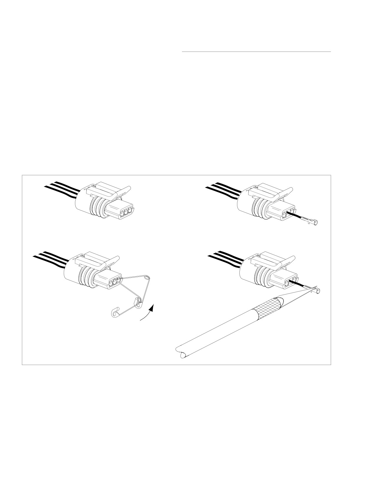
See Figure B-15. Remove the pin and push on the wire
INSTALLING PULL-TO-SEAT
end of the lead to extract the terminal from the mating
end of the connector. See item C. If necessary, pull back
TERMINALS/EXTERNAL LATCH
the conduit and remove the wire seal at the back of the
TYPE
connector to introduce some slack in the wires.
NOTE
NOTE
A series of Packard Electrical Terminal Crimp Tools are avail-
For wire location purposes, alpha characters are stamped
able to install Packard pin and socket terminals on wires.
into the socket housings.
1. See Figure B-15. To install a terminal back into the
chamber of the connector housing, use a thin flat blade,
like that on an X-Acto knife, and carefully bend the tang
outward away from the terminal body. See item D.
2. Gently pull on the lead at the wire end of the connector to
draw the terminal back into the chamber. A click is heard
when the terminal is properly seated.
3. Push on the lead to verify that the terminal is locked in
place.
4. Push the pin and socket halves of the connector together
until the latches “click.”
A
C
Locate tang on latch side of chamber.
Push on wire end of lead to remove terminal.
B
D
Pivot end of pin to depress tang.
Raise tang and re-install terminal.
x0332x7x
Figure B-15. Depress Tang and Extract Terminal From Mating End of Connector
B-14
2006 Sportster: Appendix B
HOME
SEALED BUTT SPLICE CONNECTORS
B.5
INSTALLATION
Table B-1. Wire Specifications
CONNECTOR
Butt splicing may be a necessary procedure for replacement
WIRE GAUGE
PART NO.
COLOR
of some components. Proceed as follows:
1.
Strip 3/8 inch (9.5 mm) of insulation off the ends of the
18-20
Red
70585-93
wires.
14-16
Blue
70586-93
2.
See Figure B-17. Insert wires into opposite ends of the
10-12
Yellow
70587-93
butt splice connector. Feed the wires into the connector
until the stripped ends are housed within the metal
insert. Since the size of the connectors vary with the
NOTE
gauge of the wire, reference the following table to ensure
It is acceptable for the splice to rest against the heat shrink
properly sealed splices.
tool attachment.
3.
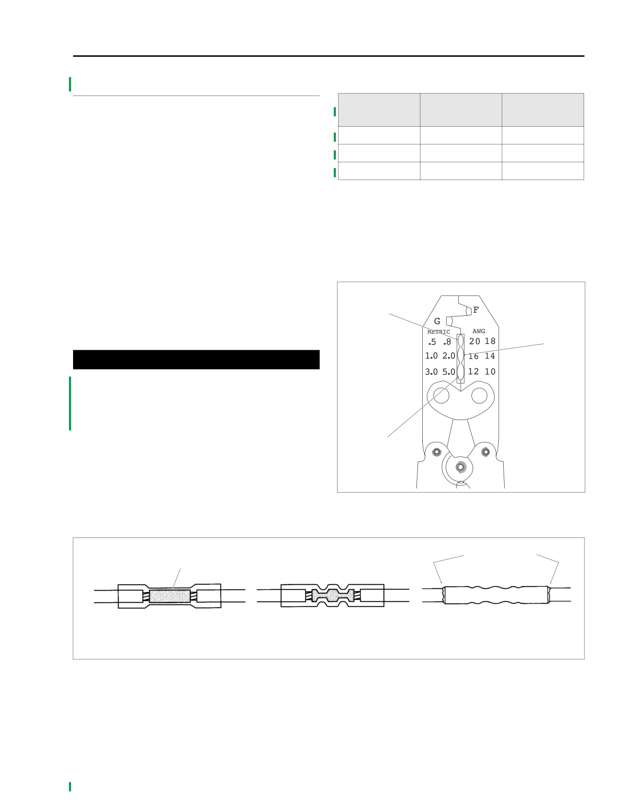
See Figure B-16. Crimp the wires within the connector
5. Heat the center of the splice until the crimp indentations
using the Packard Crimp Tool (HD-38125-8). Be sure to
disappear and the tubing assumes a smooth cylindrical
match the color or gauge wire marked on the butt splice
appearance.
connector with the corresponding crimp cavity on the
crimp tool.
x0333x7x
NOTE
If adjacent wires are being spliced, stagger the splices so that
Red
the butt splice connectors are spaced at different positions
along the length of the wires.
Blue
1WARNING
Be sure to follow manufacturer's instructions when
using the UltraTorch UT-100 or any other radiant heating
device. Failure to follow manufacturer's instructions can
cause a fire, which could result in death or serious injury.
(00335a)
Yellow
4.
See Figure B-17. Using the UltraTorch UT-100 (HD-
39969), Robinair Heat Gun (HD-25070) with heat shrink
attachment (HD-41183) or other suitable radiant heating
device, heat the crimped splice to encapsulate the butt
splice connection. Apply heat from the center of the
crimp out to each end until the meltable sealant exudes
Figure B-16.
Packard
Crimp Tool
(HD-38125-8)
out both ends of the connector.
Metal
Melted sealant
insert
Insert stripped wire
Crimp wire ends
Apply heat and allow
ends into connector
in connector
connector to cool
Figure B-17. Installing Sealed Butt Connectors
2006 Sportster: Appendix B B-15
HOME
CONNECTOR LOCATIONS
B.6
Table B-2. Sportster Electrical Connector Locations
CONNECTOR
DESCRIPTION
TYPE
LOCATION
NO.
[5]
Maxi fuse
spade terminals
on battery strap, under left side cover
[7]
tail lamp harness to main harness
6-place Multilock, black
under seat
[10]
ignition control module (ICM)
12-place Deutsch, black
under seat
[18]
left rear turn signal
2-place Multilock, white
inside tail lamp lens
[19]
right rear turn signal
2-place Multilock, black
inside tail lamp lens
[20]
instruments
12-place Deutsch, black
under fuel tank
[22]
right hand controls
6-place Deutsch, black
under fuel tank
[24]
left hand controls and horn
6-place Deutsch, gray
under fuel tank
[30]
TSM/TSSM
12-place Deutsch, gray
under battery
[31]
front turn signals
6-place Multilock, black
under fuel tank
[33]
ignition key switch
-
right side of frame behind neck
[38]
headlamp
4-place Multilock, black
under fuel tank
[39]
speedometer
12-place Packard Micro-64, black
back of speedometer
[46]
voltage regulator to stator
2-place round molded, black
in front of engine crankcase
[61]
relay/fuse block
spade terminals
under left side cover
[62]
starter relay
5-place Amp
fuse/relay block, under left side cover
[65]
vehicle speed sensor (VSS)
3-place Packard, black
right rear top of crankcase
[77]
voltage regulator (D.C. output)
2-place Packard, black
in front of engine crankcase
[79]
crank position sensor (CKP)
2-place Deutsch, black
left side, frame, beneath primary cover
[80]
manifold air pressure sensor
3-place Packard, black
top of manifold
[83]
ignition coil
3-place Packard, black
back of coil
[91]
data link connector
4-place Deutsch, gray
electrical bracket, under left side cover
[93]
tail lamp
4-place Multilock, black
inside tail lamp lens
[94]
tail lamp power in
6-place Multilock, black
inside tail lamp lens
[108]
tachometer
12-place Packard Micro-64, gray
back of tachometer
[120]
oil pressure switch
90o post terminal, black
oil pressure switch, under oil filter mount
stop lamp switch, under electrical
[121]
rear stoplight switch
spade terminals, black
bracket
[122]
horn
flag terminal (2), black
between cylinders, left side
[128]
starter solenoid
locking spade terminal, white
starter solenoid
[131]
neutral switch
1-place molded jumper, black
right side frame, beneath gearcase cover
[142]
security siren
3-place Deutsch, black
electrical bracket, under left side cover
[160]
B+ connector
1-place Packard, gray
under seat
-
harness grounds (2)
ring terminals
crankcase housing, top rear
B-16
2006 Sportster: Appendix B
HOME
INDEX TO WIRING DIAGRAMS
B.7
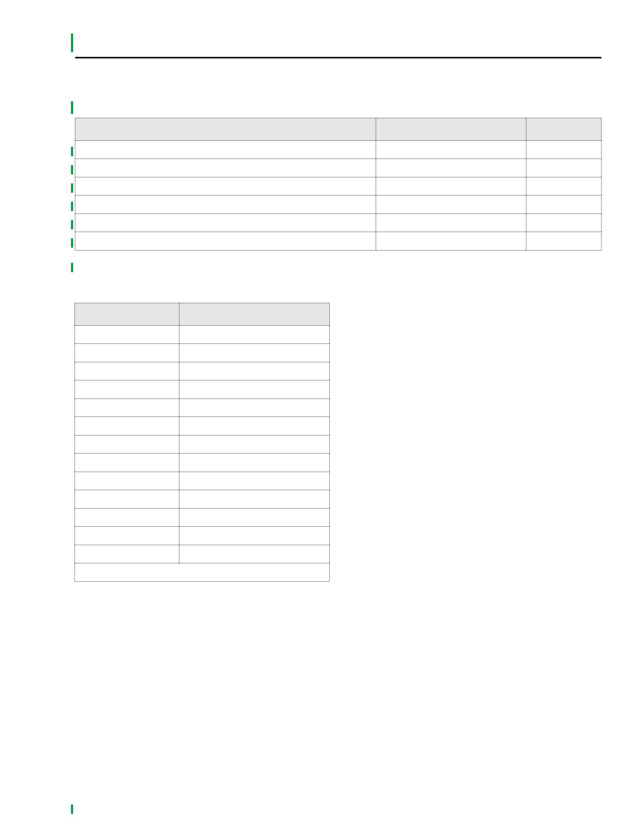
Table B-3. 2006 Sportster Wiring Diagrams
MODEL
DIAGRAM
PAGE
2006 All Sportster Dom. and Int. Models
Main Harness
B-19, B-21
2006 All Sportster Dom. and Int. Models
Ignition Circuit
B-23
2006 All Sportster Dom. and Int. Models
Starting and Charging Circuits
B-25
2006 All Sportster Dom. and Int. Models
Horn and Instruments
B-27
2006 All Sportster Dom. and Int. Models
Lights
B-29, B-31
2006 All Sportster Dom. and Int. Models
Security
B-33, B-35
Table B-4. Wire Color Code Key
ABBREVIATION
COLOR
BK
Black
BN
Brown
R
Red
O
Orange
Y
Yellow
GN
Green
BE
Blue
V
Violet
GY
Gray
W
White
PK
Pink
TN
Tan
LGN
Light Green
Wire color-XX/XX-Stripe color
2006 Sportster: Appendix B B-17
HOME
NOTES
B-18
2006 Sportster: Appendix B
HOME
xd0021xxx
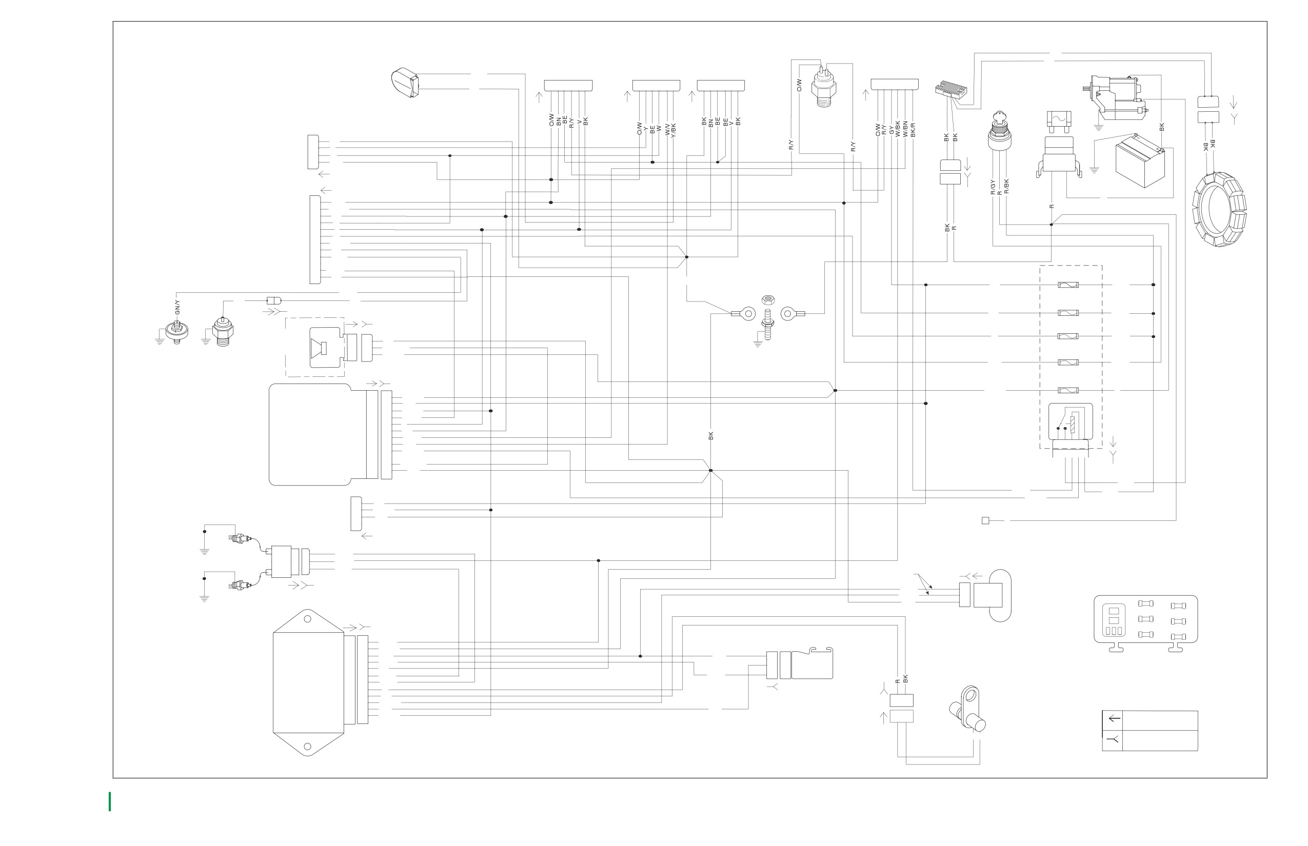
Main Harness 1 of 2
BK
HORN
LEFT HAND
FRONT TURN
RIGHT HAND
BK
REAR LAMPS
VOLTAGE
SIGNALS
CONTROL (BK)
[7A]
CONTROL (GY)
REGULATOR
STARTER
Y-BK
[24A]
[31A]
[22A]
1
2
3
4
5
6
1
2
3
4
5
6
1
2
3 4 56
1
2
3
4
5
6
BK
IGN
30 AMP
[46A]
SWITCH
MAXIFUSE
1 2
[33]
[5B]
REAR
1 2
STOPLIGHT
SWITCH
[46B]
[121]
4
BK
HEADLAMP
3
Y
2
[77A]
[38A]
W
1
O/W
B A
B
A
B
A
BATTERY
[77B]
R
1
O/W
2
BN/GY
3
BN
4
W
5
V
INSTRUMENTS
6
O
7
LGN/V
[20A]
8
TN
9
GN/Y
STATOR
[61B]
10
11
BN/V
IGNITION
POWERTRAIN
12
BK
15A
BK
GROUND
A
B
GY
R/BK
POINT
GN/Y
LIGHTS
TN
TN
15A
R
P
[136A]
[136B]
BE
R/BK
[142A]
[142B]
[GND1]
[GND2]
INSTRUMENTS
G
15A
H
OPTIONAL
0
R/BK
3
3
BK
SECURITY SIREN
ACCESSORIES
2
2
LGN/BN
OIL PRESSURE
1
1
BN/GY
15A
NEUTRAL SWITCH
D
C
SWITCH
[131]
0/W
R/GY
[120]
BATTERY
15A
[30A]
[30B]
J
I
BN/GY
R
BATTERY
1
1
BN/GY
IGNITION
2
2
GY
VSS / SERIAL DATA LINK
3
3
LGN/V
SECURITY INDICATOR
4
4
BN/V
LEFT TURN FEED
5
5
V
RIGHT TURN FEED
6
6
BN
[62A]
TURN SIGNAL/SECURITY MODULE
RIGHT TURN SWITCH INPUT
7
7
W/BN
LEFT TURN SWITCH INPUT
8
8
W/V
4
5
1
2
3
START RELAY CONTROL
9
9
TN/GN
T K USE
IGNITION ENABLE SIGNAL
10
10
ALARM SIGNAL
11
11
LGN/BN
[62B]
GROUND
12
12
BK
GN
BK/R
R/BK
TN/GN
4
GY
DATA
3
LGN/V
[160B]
LINK
2
BK
[91A]
B+ CONNECTOR
1
R
1
IGNITION
9 amp max.
COIL
1
1
Y/BE
2
2
W/BK
3
3
BE/O
[65A]
Twisted Pair
[65B]
[83A]
[83B]
1
1
BK/R
BK/BE
2
2
ACCESSORY
IGNITION
BK
3
3
START RELAY
D
C
B
A
E
15A
15A
[BLK]
BATTERY
INSTRUMENTS
[10A]
K
J
I
H
G
15A
15A
[10B]
LIGHTS
VEHICLE SPEED SENSOR
R
P
SPARE
O
M
U T S
15A
RUN/STOP SIGNAL
1
1
W/BK
BATTERY
2
2
BN/GY
+5V SENSOR PWR
3
3
R/W
R/W
C
MAP
SENSOR GROUND
4
4
BK/W
SENSOR
[61] TOP VIEW
B
MODULE GROUND
5
5
BK
[80A]
COIL FRONT
6
6
BE/O
BK/W
A
[79B]
IGNITION CONTROL MODULE
COIL REAR
7
7
Y/BE
CRANK SENSOR (+)
8
8
R
[80B]
CRANK SENSOR (-)
9
9
BK
1 2
VEHICLE SPD SIG
10
10
BK/BE
MAP SIGNAL
11
11
V/W
V/W
CRANK POSITION
DATALINK
12
12
LGN/V
1
2
SENSOR
PIN CONNECTOR
(A side)
[79A]
R BK
SOCKET CONNECTOR
(B side)
2006 ALL SPORTSTER DOM. and INT. MODELS, MAIN HARNESS, PAGE 1 OF 2
B-19
HOME
2006 ALL SPORTSTER DOM. and INT. MODELS,
2006 ALL SPORTSTER DOM. and INT. MODELS,
MAIN HARNESS, PAGE 1 OF 2
MAIN HARNESS, PAGE 1 OF 2
B-20
HOME
xd0022xxx
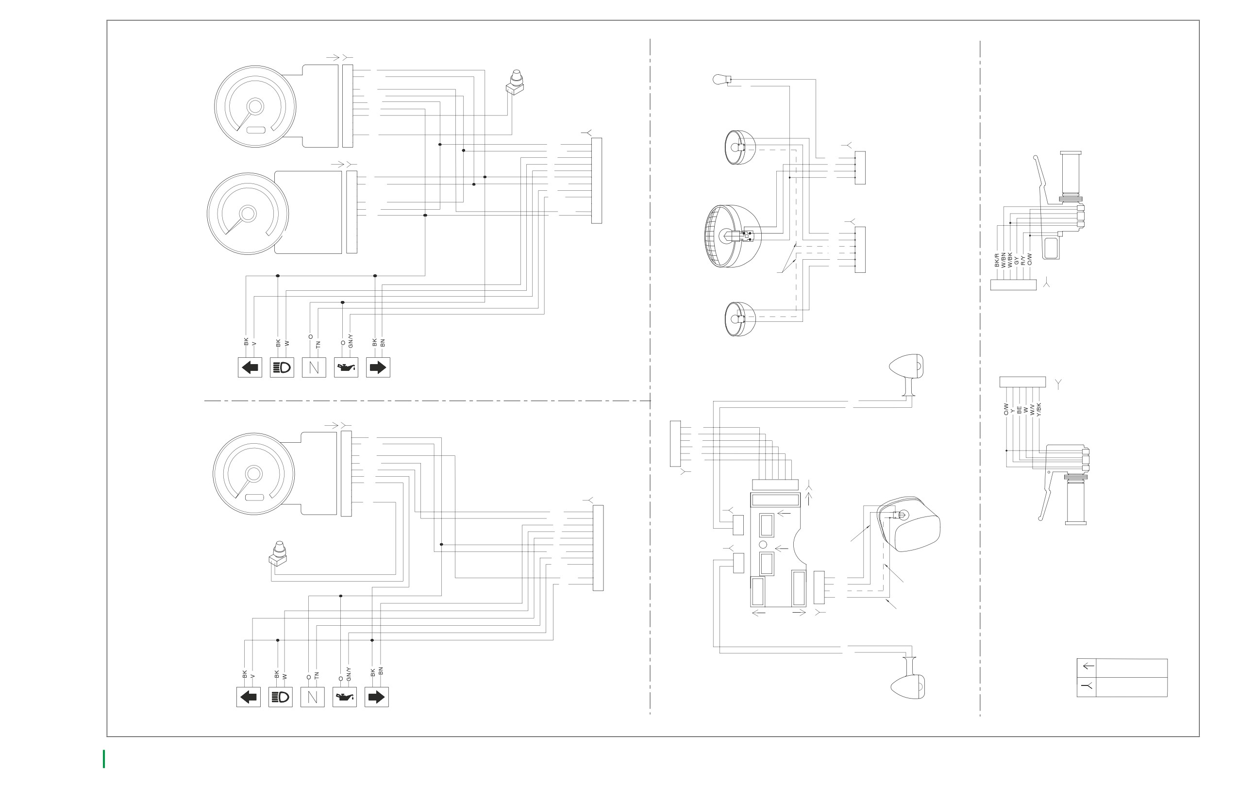
Main Harness 2 of 2
[39A]
[39B]
TRIP RESET
POSITION LAMP
SWITCH
HDI ONLY
IGNITION
1
O
DATABUS
2
LGN/V
NC
3
BK
SECURITY LP
4
BN /V
BATTERY
5
BN/GY
ACCESSORY
6
O/W
SPEEDOMETER
GROUND
7
BK
TRIP SW
8
BK
FUEL LEVEL
9
NC
10
TRIP SW
11
BK
[38B]
NC
12
O-W
1
RIGHT
BN/GY
2
TURN
BN
3
O/W
1
[108A]
[108B]
W
4
W
2
HAND CONTROLS,
V
5
TO
[
212]
Y
3
RIGHT
IGNITION
1
O
O
6
MAIN
BK
4
[162 ]
DATALINK
2
LGN/V
LGN/V
7
HARNESS
NC
3
TN
8
[20B]
PURSUIT
4
GN/Y
9
RPM x 100
HEADLAMP
BATTERY
5
BN/GY
10
ACCESSORY
6
RIGHT TURN SWITCH
O/W
BN
/V
11
[31B]
TACHOMETER
GROUND
7
BK
BK
12
ENGINE STOP/RUN SWITCH
NC
8
NC
9
START SWITCH
CRUISE ENGAGED
BK
1
10
STOPLIGHT SWITCH
NC
11
BN
2
CRUISE ENABLE
12
BE
3
BE
4
V
5
BK
6
[
182
]
DOM ONLY
[22B]
6
5
4
3
2
1
LEFT
TURN
[214]
CONFIGURATION FOR XL1200R
RIGHT
TURN
[190]
1
2
3
4
5
6
[24B]
BK
V
[39A]
[39B]
6
BK
5
V
IGNITION
1
O
4
R/Y
DATABUS
2
LGN/V
3
BE
NC
3
HORN SWITCH
2
BN
SECURITY LP
4
BN /V
1
O/W
HEADLAMP HI/LO SWITCH
BATTERY
5
BN/GY
ACCESSORY
6
O/W
LEFT TURN SWITCH
SPEEDOMETER
GROUND
7
BK
[94B]
[7B]
TAIL LAMP
TRIP SW
8
BK
6
5 4
3
2
1
FUEL LEVEL
9
[198]
HAND CONTROLS,
NC
10
6
5 4
3
2
1
LEFT
TRIP SW
11
BK
[19B]
NC
12
[163]
O/W
1
[94A]
BN/GY
2
1
1
[19A]
BN
3
2
2
W
4
TRIP RESET
V
5
TO
SWITCH
6
O
MAIN
BRAKE LIGHT
LGN/V
7
HARNESS
[18B]
TN
8
1
[18A]
[20B]
1
GN/Y
9
2
2
10
BN /V
11
4
4
BK
BK
12
1
3
3
R/Y
2
2
2
O/W
RUNNING LIGHT (HDI)
3
1
1
BE
RUNNING LIGHT (DOM)
[93A]
[93B]
V
BK
PIN CONNECTOR
(A side)
LEFT
SOCKET CONNECTOR
CONFIGURATION FOR XL883, XL883L, XL883R, XL883C, XL1200C
TURN
(B side)
[ 194]
2006 ALL SPORTSTER DOM. and INT. MODELS, MAIN HARNESS, PAGE 2 OF 2
B-21