Harley Davidson 2005 MOTORCYCLE. PREDELIVERY AND SETUP MANUAL - page 6
-------------------------------------------------------------------------------------------------------------------------------------------------------------
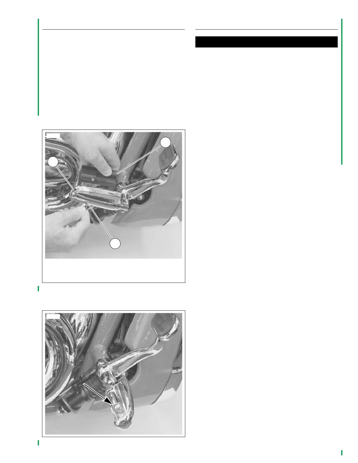
FOOTREST ADJUSTMENT
FINAL PREDELIVERY INSPECTIONS
If it is necessary to rotate rider or passenger footrests for cus-
CAUTION
tomer comfort, proceed as follows:
Do not use sharp objects to peel protective film from
1. See Figure 7-8. Remove screw (2) and footrest rubber
console insert and clutch release cover in the next two
insert (3) from footrest assembly (1).
steps. Sharp objects can scratch and damage finished
surfaces.
2. See Figure
7-9. Loosen footrest adjustment screw.
Rotate footrest assembly to desired angle. Tighten screw
1. The airbox console insert is protected during shipment
to 25.8 Nm (19 ft-lbs).
by a clear plastic film. Carefully peel the film away from
the console insert.
3. See Figure 7-8. Reinstall rubber insert (3) into footrest
2. The clutch release cover (righthand side of engine) is
assembly (1) and secure with screw (2). Tighten to 4.0-
protected during shipment by a clear plastic film. Care-
6.0 Nm (35-53 in-lbs).
fully peel the film away from the clutch release cover.
NOTE
Perform all the remaining Predelivery Inspections given in
10772
Section I (All Models) and Section VI (VRSC Models) that
3
apply to the VRSCA.
DO NOT REPEAT INSPECTIONS THAT WERE PER-
1
FORMED IN THIS SECTION.
2
1.
Footrest assembly
2.
Screw
3.
Rubber insert
Figure 7-8. Removing Footrest Rubber Insert
10773
Figure 7-9. Footrest Adjustment Screw
2005 PDI: CVO Models
7-7